Abstract
Shazand Railway Bridge is located in Markazi province, Iran in north to south-west railway. The bridge consists of ten spans. In 1984, during Iran-Iraq war, that’s main span, which has a length of 72 m, was attacked and severely damaged. Eight month later, damaged span replaced with a steel deck. The deck is straight in plan, but the railway is curved and this causes eccentricity. Excessive vibration was observed during the train passage. Although the bridge was retrofitted in two stages, the problem has not been solved yet, and the trains’ speed should be reduced to around 10 km/h in order to avoid excessive vibration. The present study addressed the effectiveness of tuned mass damper (TMD) in reducing train-induced vibrations of Shazand Railway Bridge. A three dimensional finite-element model of the bridge is developed and dynamic time history analyses under train passage in both as-built and passively controlled with TMD are conducted. Sensitivity analyses are performed to demonstrate the effects of the damper parameters on structural response. The results show that considerable reduction in acceleration response of the bridge can be achieved by employing proper TMD.
1. Introduction
Shazand Railway Bridge is one of the most famous historical stone arch bridges in Iran. Shazand Railway Bridge was constructed in 1937 and opened to traffic in 1939. This bridge is located in of Markazi Railway route, between Samangan and noorabad. The bridge is near Shazand station, and it is constructed across a river. The bridge located between two tunnels and has 9 spans of 10 m and 1 main span with 72 m length. Railway of North to Southwest is one of the strategic routes of Iran. This route has a single rail line and has a light terrific density.
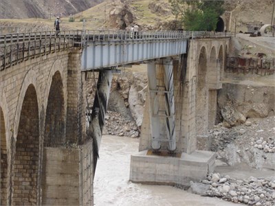
This bridge had a significant effect in War between Iran and Iraq. In that war, the bridge repeatedly attacked by air strike but was not damaged significantly. In 1987, air attack caused severe failure of the main span of the bridge and the railroad was disconnected. It was necessary to reopen the supply route immediately. New steel deck designed, and implanted in 1990. The steel deck is straight in a plan, but the railway is curved and this caused eccentricity. Fig. 1 shows cross-section of the bridge and eccentricity of the rail line. The length of the steel deck is 72 m and consists of six 2.5 m depth steel plate girders connected by cross brace and chord. At each abutment, the deck rests on six non-seismic elastomeric pads. The steel bridge had excessive vibration due trains passing; therefore, speed of trains limited to 6 kilometres per hour. During the war, the steel bridge was attacked several times, but was not seriously damaged. After the war, the bridge retrofitted in two stages. In the first stage, the bridge post-tensioned with 16 cables to reduce negative stresses. In the second stage, four oblique columns added to the bridge. These columns divided the bridge to 3 spans with length of 15, 42 and 15 m. Fig. 2 shows Shazand Bridge after retrofitting.
The problem did not solve entirely with these retrofitting, just speed of trains arose to 10 kilometers per hour. Field tests on the bridge showed that the acceleration of middle of the bridge reaches close to 1 g.
Fig. 1Cross section of the bridge and railway
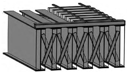
Fig. 2Shazand bridge after two retrofitting
Using Tuned Mass Damper (TMD) is one of the techniques to suppress vibrations. TMD is a classical control device and it is made of a mass, a spring and a viscous damper. The concept of TMD was proposed by Frahm [1]. Den Hartog added a damper to Frahm’s devices and proposed an optimal design for TMDs under harmonic load [2]. Philosophy of using TMD is a reduction of structural vibration energy. This reduction is accomplished by transferring some of the vibration energy of structure to the TMD. This devise has a variety of merits; it has permanent servise time, requires easy management and maintenance, and it can be simply incorporated into an existing structure with less interference on main performance of the structure. In summary, its advantages include compactness reliability, efficiency and low cost. TMDs have been extensively studied and applied to attenuate wind and earthquake induced vibrations. Most of the theoretical analyses, experimental researches and practical uses have been shown that TMD is an effective to suppress structural vibrations. Several researchers have investigated using of TMD in reducing the vibration of a bridge under traffic loads. Kwon et al. studied the use of TMD to suppress vibrations of a three-span bridge under TGV train passage. They concluded that TMD can reduce 21 % of maximum displacement, and quickly suppress the free vibrations [3]. Wang et al. created numerical and analytical of Taiwan High-Speed Railway and investigated the performance of TMD to suppress the train-induced vibrations. The numerical results showed TMD can reduce up to 40 % of acceleration of the moderately long bridge under train's passage. They concluded that interaction effect between bridge and train is of no significant effect on TMD’s performance [4]. In present study the effectiveness of TMD in reducing train-induced vibrations of Shazand Railway Bridge is addressed. A three dimensional finite-element model of the bridge is developed and dynamic time history analyses under train passage in both as-built and passively controlled with TMD are conducted. Sensitivity analyses are performed to demonstrate the effects of the damper parameters on structural response.
2. Equations of motion of the bridge and TMD
For the formulation of bridge responses, these assumptions are used: 1 – the bridge is idealized as having permanent stiffness in its length, 2 – train is modeled as moving forces, 3 – the train moves at a constant speed on the bridge, 4 – only vertical modes of the bridge considered. The equation of motion can be expressed as:
in which – matrix of mass, – matrix of damping, – matrix of stiffness and and are interaction force between bridge and train and between TMD and the bridge, respectively. In all cases, initial set of loads are considered to be these of the first axle of the train when it enters the bridge. Let be the longitudinal distance from the th train load set to the initial train load set on the bridge. and stand for the number of first and last train axles on the bridge. At time , and are given by:
where – dirac delta function, – speed of a train – static load of ith wheel of train, and – damping and spring constant of the TMD, respectively, – vertical vibration displacement of middle of the bridge, – vertical vibration displacement of the TMD and a dot represents derivative with respect to time.
Jianzhong et al. investigated a simply supported girder bridge under high-speed trains with an emphasis on the resonant vibration. They proposed Eq. (4) for resonant speed of trains and concluded that the number of wheel-axle of train passage across the bridge is also an important factor in bridge resonant vibration [5]:
in this equation – distance between train axles, – fundamental frequency of the bridge.
3. Optimum parameters of tuned mass damper
Den Hartog proposed formulas for obtaining optimum parameters of TMD. These formulas are obtained for reduction responses of structure with single degree of freedom under harmonic load excitation [2]. Den Hartog formulations are given as:
where is mass ratio of TMD. Having and , optimum values of damping coefficient and stiffness of the TMD can be calculated as:
in which – Main structure frequency, – TMD mass.
Sadak et al. proposed TMD optimum parameter for multi degree of freedom (MDOF) structure under earthquake excitation. Results shown that with the use of optimum parameter, significant reduction of structural responses can be achieved [6]. Sadak et al. formulations are given as:
where is the damping ratio of main structure, is the amplitude of fundamental mode of vibration for a unit modal participation factor computed at location of TMD and is the mass ratio for MDOF structure. can be calculated as:
in which is the TMD mass, is the mass matrix of structure and is fundamental mode shape normalized to have a unit participation factor.
4. Response of the bridge under train induced vibration
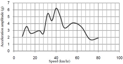
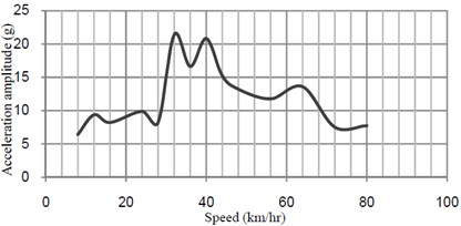
The external moving point loads that acting on the bridge and the longitudinal distance between axles of the train are shown in Fig. 3. The maximum fast Fourier transform (FFT) acceleration versus speed at midspan of the bridge is shown in Fig. 4.
Fig. 5 shows the time history of dynamic deflection and their FFT at midspan of the bridge when the train moves over the bridge at the resonant speed. The time histories of dynamic acceleration and their FFT at midspan in directions transverse and vertical directions of the bridge at the speed of 32 km/h and 40 km/h are shown in Fig. 6.
Fig. 3Moving point loads and longitudinal distances between axle of used train (ton-m)
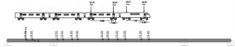
Fig. 4Acceleration-speed curves at midspan of bridge without TMD
a) Transverse direction
b) Vertival direction
ISO purposed that maximum sensitivity of human to acceleration in vertical direction is in the frequency range of 4 to 8 Hz [7]. These excessive vibrations have a disturbing effect on passengers.
5. Response of the bridge with TMD
In this section, TMD is installed to reduce governing mode of vibrations of the bridge. Governing modes of bridge are shown in Table 1. The bridge has very closed two governing modes.
TMD is tuned to the frequency of vibration and its performance with 0.005 and 0.01 are investigated. Fig. 7 shows the performance of TMD to reduce excessive vibrations.
Fig. 5Time-histories of vertical deflection and their FFT at midspan of the bridge without TMD
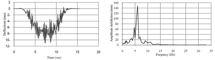
a)32 (km/h)
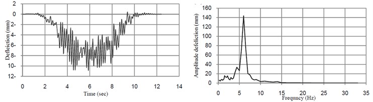
b)40 (km/h)
Fig. 6Time histories of vertical acceleration and their FFT at midspan of the bridge without TMD
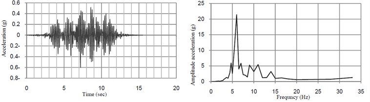
a)32 (km/h)
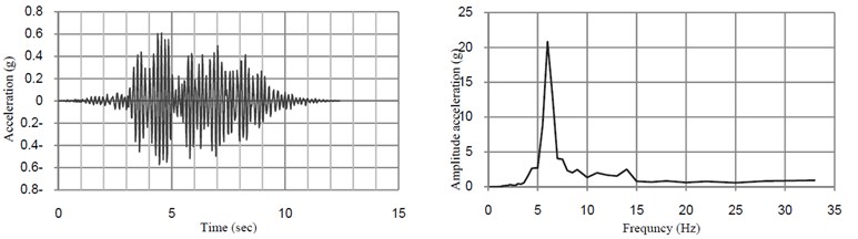
b)40 (km/h)
Table 1Governing mode of bridge
Mode number | Frequency (Hz) | Mode shape |
6 | 6.21 | Twisting |
7 | 6.23 | Flexural |
5.1. Effect of tuned frequency in performance of TMD
In this section, the sensitivity of TMD to various tuning frequency is studied. Trains with different mass can change frequency of fundamental mode of the bridge. Effects of TMD’s tuning frequency of are shown in Fig. 8.
TMD has effective performance when is tuned to the vicinity of the frequency of the governing mode of the bridge. Various types of trains with different masses have detuning effect because the bridge frequency is changed under trains passing.
Fig. 7Acceleration-speed curves at midspan of bridge with and without TMD
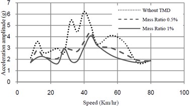
a) Transverse direction
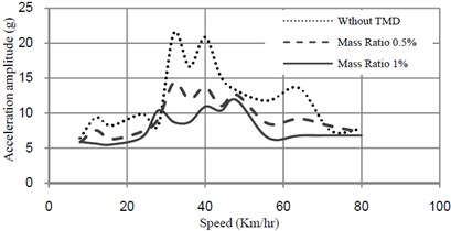
b) Vertical direction
Fig. 8Acceleration-frequency curves at midspan of the bridge mass ratio of TMD = 0.5 %
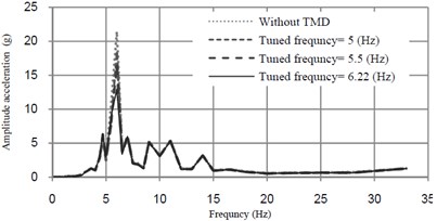
a)32 (km/h)
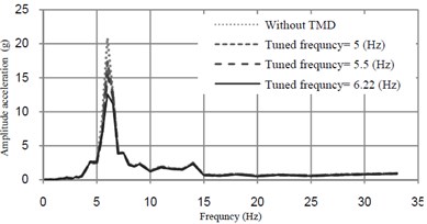
b)40 (km/h)
5.2. Effect of damping ratio
Fig. 9 shows the changes in the acceleration-frequency amplitude response curves of the bridge due to different values of damping ratios of TMD. Mass ratio and frequency of TMD are respectively, selected as 0.5 % and 6.22 Hz.
From Fig. 9, it can be seen that the optimum damping ratio of TMD is very small.
Fig. 9Acceleration-frequency curves at midspan of bridge mass ratio of TMD = 0.5 % and tuned frequency = 6.22 (Hz)
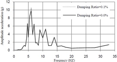
a)32 (km/h)
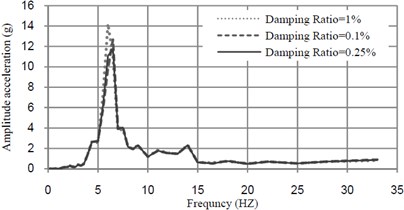
b)40 (km/h)
5.3. Effectiveness of TMD for suppression of resonant phenomenon
The analyzed time-histories of deflection and acceleration at midspan of the bridge at the speed of 32 km/h and 40 km/h are shown in Figs. 10 and 11.
Fig. 10Acceleration-time amplitude response curves at midspan of the bridge mass ratio of TMD = 1 % tuned frequency = 6.22 (Hz)
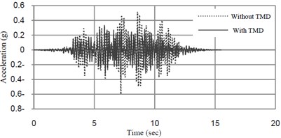
a)32 (km/h)
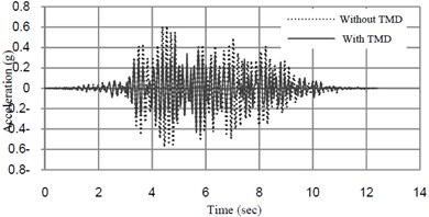
b)40 (km/h)
Fig. 11Deflection-time amplitude response curves at midspan of the bridge mass ratio of TMD = 1 % and tuned frequency = 6.22 (Hz)
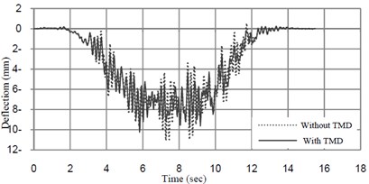
a)32 (km/h)
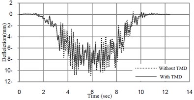
b)40 (km/h)
Table 2Maximal response of the bridge with and without TMD
Speed (km/h) | TMD Condition | Maximal vertical acceleration (g) | Maximal transverse acceleration (g) | Maximal vertical displacement (mm) | Maximal transverse displacement (mm) |
32 | Without TMD | 0.52 | 0.18 | –10.71 | 3.56 |
TMD with 0.5 % mass ratio | 0.42 | 0.15 | –10.47 | 3.36 | |
Reduction percentage | 18.24 | 17.01 | 2.22 | 5.49 | |
TMD with 1 % mass ratio | 0.34 | 0.13 | –10.25 | 3.38 | |
Reduction percentage | 35.14 | 27.75 | 4.23 | 5.17 | |
40 | Without TMD | 0.61 | 0.18 | –10.89 | 3.28 |
TMD with 0.5 % mass ratio | 0.48 | 0.15 | –10.35 | 3.09 | |
Reduction percentage | 22.06 | 18.65 | 4.93 | 5.73 | |
TMD with 1 % mass ratio | 0.44 | 0.15 | –10.23 | 2.98 | |
Reduction percentage | 27.76 | 15.78 | 6.07 | 8.96 |
The results of the analyses are summarized in Table 2. The result shows that TMD is effective in reducing acceleration of the bridge, but it has not considerable effect on reducing displacement response of the bridge.
6. Conclusion
In this study, TMD is used to suppress the vibration of Shazand Railway Bridge under passing train. The performance of TMD with parameters of the tuned frequency, damping ratio and mass ratio are investigated. From the results the following conclusions may be drawn:
• When natural frequencies of the bridge are multiples of the frequency of the train excitation, the resonant effect will occur and cause excessive vibrations of the bridge.
• The bridge has two close natural modes that cause two close resonant speeds. The resonant speeds of tested trains are 32 km/h and 40 km/h.
• TMD with optimum parameter, significantly reduces acceleration of the bridge, but it has not very effective in suppressing deflection of the bridge.
References
-
Frahm H. Device for Damping Vibrations of Bodies. US Patent #989958, 1909.
-
Den Hartog J. P. Mechanical Vibration. McGraw-Hill, New York, 1956.
-
Kwon H. C., Kim M. C., Lee I. W. Vibration control of bridges under moving loads. Computers and Structures, Vol. 66, Issue 4, 1998, p. 473-480.
-
Wang J. F., Lin C. C, Chen B. L. Vibration suppression for high-speed railway bridges using tuned mass dampers. International Journal of Solids and Structures, Vol. 40, 2003, p. 465-491.
-
Jianzhong L., Mubiao S. The resonant vibration for a simply supported girder bridge under high speed trains. Journal of Sound and Vibration, Vol. 224, Issue 5, 1999, p. 897-915.
-
Sadek F., Mohraz B., Taylor A. W., Chung R. M. A method of estimating the parameters of tuned mass dampers for seismic applications. Earthquake Engineering and Structural Dynamics, Vol. 26, 1997, p. 617-635.
-
Evaluation of human exposure to whole-body vibration. Part 2: continuous and shock-induced vibration in buildings (1_80 Hz). International organization for standards, ISO-2631/2-(E), Geneva, Switzerland, 1989.
About this article

The work was executed with financial support from Petrochemical Industries Development Management Company of the Iran.
