Abstract
Wind-induced vibration control of power transmission tower using pounding tuned mass damper is studied in the paper. The power transmission tower, which is often a high and flexible structure, is very susceptible to wind-induced vibrations. To reduce the wind-induced vibration of a transmission tower, a new type of vibration control device that pounding tuned mass damper (PTMD) is proposed in the PTMD, a limiting collar with viscoelastic material laced on the inner rim is installed to restrict the stroke of the tuned mass and to dissipate energy through collision. The pounding force is modeled based on the Hertz contact law. A 55 m tower is selected to verify the effectiveness of the PTMD. The wind field is generated based on Kaimal spectrum using harmonic superposition method. The power transmission towers without control and with the PTMD are analyzed, respectively. Results show that the PTMD is very effective in reducing the wind-induced vibration and the vibration control performance improves as the external wind load increases.
1. Introduction
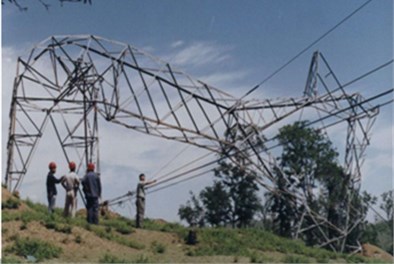
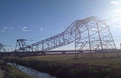
With the development of the national economy, the demand for electric power is growing dramatically. The high-voltage transmission tower is a vital component in the power transmission system. However, the transmission tower is often a high and flexible structure with low damping associated with the fundamental oscillation mode. This configuration makes it very vulnerable to wind-induced vibrations [1]. Recent investigations have reported several tower failures due to wind excitation [2, 3]. The wind induced collapse of transmission towers is shown in Fig. 1. Consequently, it is very important to reduce the wind-induced vibration of a transmission tower and thus improving its reliability.
Fig. 1Wind induced collapse of transmission towers
To date, most retrofitting practices for transmission towers employ only static approaches such as increasing member section area or shortening effective member length by additional member [2]. These methods will tremendously increase the project cost and thus is not financially acceptable. An alternative approach is to install vibration control devices. The vibration control devices designed for transmission towers can be divided into two categories. One category aims to enlarge the damping ratio by incorporating energy dissipating dampers such as friction-type reinforcing members [2], magneto rheological (MR) dampers [4], viscoelastic dampers (VED) [5], lead viscoelastic dampers (LVED) [6] and giant magnetostrictive material (GMM) actuators [7]. The other category aims to absorb the vibration energy from the primary transmission tower using attached dynamic absorbers. Kilroe [8] installed vibration absorbers on members of tower arms to mitigate the fatigue phenomena. Battista et al. [9] proposed a nonlinear pendulum-like damper (NLPD), and the nonlinear pendulum-like dampers installed on the towers were envisaged. Tian et al. [10] investigated the optimal parameter of TMD and the responses of transmission tower-line system with and without optimal TMD under wind excitations using SAP2000. The results show that, at any moment of wind response time history, the optimal TMD can effectively reduce wind vibration, which have great significance for real construction and practical engineering application. Zhang et al. [11] proposed to utilize the internal resonance feature of the SP in order to reduce the wind-induced vibration of the power transmission tower-line system. The results show that the spring pendulum absorbs more energy and reduces the oscillation more effectively than those of the suspended mass pendulum. In above studies, the NLPD, TMD and SP for transmission towers under wind excitation were carried out. Nevertheless, these dynamic absorbers often utilize a damping element to dissipate the absorbed energy. The damping element often demands continuous maintenance, which is unrealistic in practical project [12]. An alternative device is the impact damper. Its features, such as easy to install and maintenance free, make it very attractive for practical implementation [13]. To date, the pounding tuned mass damper (PTMD) for transmission towers under wind excitation has not been investigated.
In this paper, the PTMD is proposed to improve the wind-resistant performance of a transmission tower. The PTMD can be regarded as combination of the traditional TMD and the impact damper. It utilizes the tuned mass to absorber vibration energy and dissipates the absorbed energy through collisions. To examine the performance of the PTMD, a pounding force model is established based on the Hertz contact law. A 55 m tower is selected as the primary structure to be controlled. The wind field is generated based on Kaimal spectrum using harmonic superposition method. The power transmission towers without control and with the PTMD are analyzed, respectively.
2. Schematic of the PTMD
In concept, the PTMD can be regarded as a combination of a PTMD and an impact damper. Fig. 1 compares the schematic of a TMD, an impact damper and the PTMD. As shown in Fig. 2(a), the TMD is an added mass () connected to the primary structure () by a spring and a damping element. It can absorb kinetic energy from the primary structure and dissipate the absorbed energy through the damping element. However, the control effectiveness is very sensitive to the damping ratio of these damping elements. It’s troublesome to design, manufacture, install and maintain a damper of a specific damping ratio in practical project. An alternative vibration suppression device is the impact damper [12, 13]. Fig. 2(b) shows the schematic of an impact damper. It is a free moving mass restricted by boundaries mounted on the primary structure. The moving mass can collide on the boundaries, resulting in large amount energy dissipation and momentum exchanges. Previous studies [12] have shown that the impact damper is more effective than the TMD in mitigating the response of a lightly damped structure under dynamic loading. Fig. 2(c) shows the schematic of the PTMD. The PTMD is basically a tuned mass constrained by two boundaries. It has two vibration mitigation mechanisms: when the tuned mass vibrates between the two boundaries, it absorbs the kinetic energy as a TMD; when the mass impacts on either boundary, it dissipates the absorbed energy as an impact damper. Li and Darby [12] found that by introducing a flexible buffer zone between the moving damper mass and the boundaries can enhance the vibration control effect. Therefore, boundaries of the PTMD are covered with viscoelastic materials.
Fig. 3 illustrates the PTMD designed for vibration control of a transmission tower. A metal ball is hanged by a cable inside a pipe. The length of the cable is determined so as to match the natural frequency of the tower. The pipe’s inner surface is covered with viscoelastic material. When the ball impacts it, the pipe can dissipate the kinetic energy and restrict the motion of the ball.
Fig. 2Schematic of TMD, impact damper and PTMD
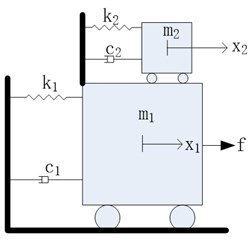
a) TMD
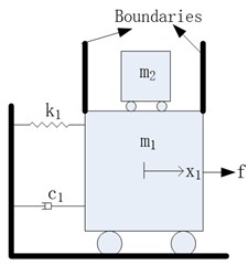
b) Impact damper
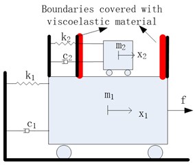
c) PTMD
Fig. 3PTMD designed for a transmission tower
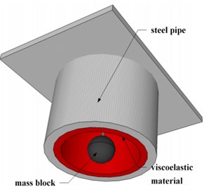
a) 3D diagram
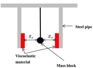
b) Cross-section diagram
3. Model of the pounding force
A numerical model is required to analyze the response of a structure controlled by a PTMD. During the past decade, several models have been proposed to study the impact of an adjacent building in severe earthquakes. Among them the nonlinear model based on the Hertz contact element in conjunction with a damper is most precise [14], and therefore is adopted in this paper. The pounding force is expressed as:
where and are the displacements of the pounding motion limiting collar and the mass block, is the gap between them. is the relative pounding deformation and is the relative velocity. is the pounding stiffness coefficient that mainly depends on material properties and the geometry of colliding bodies. Since the viscoelastic material is highly nonlinear, the impact dampingis not constant. It depends on the pounding stiffness and the deformation of the viscoelastic layer. At any instant of time its value can be obtained from Eq. (2):
where and are the masses of the two colliding bodies, and is the impact damping ratio correlated with the coefficient of restitution , which is defined as the relation between the post-impact (final) relative velocity, , and the prior-impact (initial) relative velocity, , of the two colliding bodies:
The coefficient’s values can be easily determined experimentally by dropping a sphere on a massive plane plate and observing the rebound height:
where and are the initial height and rebound height, respectively.
After assessing the value of , the pounding stiffness can be determined numerically through iterative simulations, which tend to fit the experimentally obtained pounding force time histories. Zhang et al. [15] performed an experiment and estimated that 0.2 and 17259 N/m3/2.
4. Model of the transmission tower-PTMD system
4.1. Model of the power transmission tower
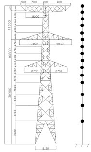
A practical transmission tower-line system illustrated in Fig. 4 is chosen as the primary structure to be controlled to investigate the vibration control performance of the proposed PTMD. The transmission tower is constructed of Q345 angle steels. Its height is 53.9 m. The nonlinear pounding force model currently cannot be implemented into any commercial finite element method. Consequently, the transmission tower is represented by a simplified multi-mass model as shown in Fig. 5.
Fig. 4SZ21-type tangent transmission tower in Liaoning province, China
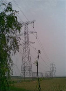
Fig. 5Simplified model of the transmission tower (mm)
4.2. Model of the tower-PTMD system
Equation of motion of the tower-PTMD system can be expressed as:
where , and are the acceleration, velocity and displacement of the tower and pounding TMD, denotes the ground acceleration and implies the pounding force calculated by Eq. (1). , and are the mass, damping and stiffness matrices, respectively:
where , and are the mass, damping and stiffness matrices of the tower structure. , and are the mass, damping and stiffness of the damper. and are coupling matrices of the damping matrix and stiffness matrix. The PTMD is added to node 15, so and are defined as:
In Eq. (6) is a column vector of ones, denotes the location of the pounding force and is defined to determine the direction of pounding force:
where and are the displacements of damper and top node of the tower, respectively, and denotes the gap between the mass block and the viscoelastic material.
5. Simulation of the wind field
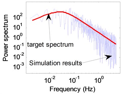
The wind excitations of transmission tower-line system are simulated by harmony superposition method. The target power spectrum is Kaimal fluctuating wind power spectrum [16]. In order to study the stability and influence of the wind load intensity on the vibration control performance of the PTMD, the mean wind velocity at the height of 10 meters above the ground is selected as 20 m/s, 30 m/s and 40 m/s.
Fig. 6Time history of wind speed at the top of the tower, V10= 40 m/s

Because the transmission tower nodes are numerous, it is difficult to simulate the wind velocity history for every node of the tower. Consequently, the transmission tower is simplified by 15 regions as shown in Fig. 6. The fluctuating wind acts only on the center of each region. The position of each region center and windward area are listed in Table 1. Fig. 7 shows the wind speed on the top of the tower of the 40 m/s case. Fig. 7 compares the target wind power spectrum and the simulated time history of the fluctuating wind. As shown in the figure, the simulation results agree well with the target spectrum.
Table 1The position of wind load and windward area
Region | Height of the region center (m) | Windward area (m2) |
1 | 9.00 | 7.083 |
2 | 15.0 | 4.507 |
3 | 19.5 | 1.868 |
4 | 24.0 | 2.435 |
5 | 26.8 | 2.369 |
6 | 30.0 | 2.344 |
7 | 32.4 | 2.029 |
8 | 35.2 | 1.672 |
9 | 37.9 | 1.602 |
10 | 40.6 | 1.810 |
11 | 43.4 | 1.591 |
12 | 46.2 | 1.117 |
13 | 48.8 | 1.062 |
14 | 51.4 | 1.164 |
15 | 53.9 | 0.611 |
Fig. 7Power spectral comparison between simulated and theoretical wind samples
6. Vibration control performance
In this section, a PTMD is designed to suppress the wind-induced vibration of the transmission tower. In order to evaluate the vibration control effectiveness of the proposed PTMD, the vibration reduction ratio is defined as:
where and are the responses of the tower with and without control devices. They can be the maximum value or the root mean square value (R.M.S.).
Figs. 8-10 show the results of the 40 m/s Case. Results of 20 m/s Case and 30 m/s Case are very similar to that of the 40 m/s Case. Therefore, the figures of those two cases are omitted in this paper. The vibration reduction ratios of those two cases can be found in Table 2.
Fig. 8Displacement time history at top of the tower 2, V10= 40 m/s

Fig. 9Acceleration time history at top of the tower 2, V10= 40 m/s

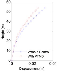
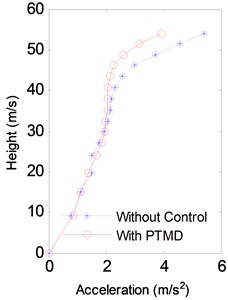
Fig. 8 and Fig. 9 compare the displacement and acceleration at the top of the tower from 400 s to 500 s in the 40 m/s Case. It is clear that the proposed PTMD is very effective in reducing the wind-induced vibration. The R.M.S. value of the displacement was reduced by 39.8 % and the acceleration by 35.3 %. Fig. 10 shows the envelopes of displacements, accelerations and internal forces of the transmission tower. The maximum displacement and acceleration was effectively reduced by the PTMD by 17.9 % and 24.6 %. The maximum axial force was also significantly mitigated with the reduction ratio to be 21.1 %.
Fig. 10Envelope of the response of the V10= 40 m/s Case
a) Displacement
b) Acceleration
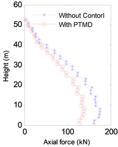
c) Axial force
The PTMD is a nonlinear damper in essential. Thus its vibration control performance may be influenced by the intensity of external loads. Table 2 lists the vibration reduction ratio of the PTMD under 3 cases, namely the 20 m/s case, the 30 m/s Case and the 40 m/s Case. It is clear from Table 2 that the vibration performance is influenced by the level of wind loads. As the wind speed increases, the vibration reduction ratio of the PTMD also increases, which implies that the PTMD is more effective under strong winds. The vibration reduction ratio of the maximum acceleration increases more significantly than those of maximum displacement and maximum axial force with the wind speed increasing. The impact damper would play a greater role due to the larger level of wind loads.
Table 2Comparison of the vibration reduction ratio of PTMD
Wind speed | RMS of Disp. | RMS of Acc. | Max Disp. | Max Acc. | Max axial force |
20 m/s | 31.0 % | 22.8 % | 12.5 % | 9.9 % | 12.4 % |
30 m/s | 36.2 % | 30.1 % | 14.3 % | 16.4 % | 16.9 % |
40 m/s | 39.8 % | 35.3 % | 17.9 % | 24.6 % | 21.1 % |
7. Conclusion
In this paper, the PTMD was proposed for the suppression of wind-induced vibration of the transmission tower. The viscoelastic material was adopted to dissipate the energy absorbed by the tuned mass through collision. The pounding force model was established based on the Hertz contact law. A practical transmission tower was established to assist numerical study. The transmission tower was simulated by a multi-mass model. The wind field is generated based on Kaimal spectrum using harmonic superposition method. Based on theoretical analysis and numerical simulation results, the following conclusions are drawn: (1) the PTMD is very effective in reducing the wind-induced vibration of a transmission tower; (2) as the intensity of the wind load increases, the vibration control performance of the PTMD also increases.
In this paper, parameters of the PTMD were not optimized. In further study, influence of these parameters on the vibration control performance should be investigated to achieve optimal design.
References
-
Li C., Li J., Yu Z. A review of wind-resistant design theories of transmission tower-line systems. Journal of Vibration and Shock, Vol. 28, 2009, p. 15-25, (in Chinese).
-
Park J., Moon B., Min K., Lee S., Kim Kyeong C. Cyclic loading test of friction-type reinforcing members upgrading wind-resistant performance of transmission towers. Engineering Structures, Vol. 29, 2007, p. 3185-3196.
-
Xie Q., Zhang Y., Li J. Investigation on tower collapses of 500 kV renshang 5237 transmission line caused by downburst. Power System Technology, 2006, p. 59-63+89, (in Chinese).
-
Chen B., Zheng J., Qu W. Control of wind-induced response of transmission tower-line system by using magnetorheological dampers. International Journal of Structural Stability and Dynamics, 2009, p. 661-685.
-
Wang W., Zhao D., Zhong W., Xu J., Ling J., Xiao X. Effect of wind-induced vibration’s control for high-voltage transmission tower based on prototype measurement. Journal of Central South University (Science and Technology), Vol. 44, 2013, p. 3911-3917, (in Chinese).
-
Li L., Yin P. The research on wind-induced vibration control for big-span electrical transmission tower-line system. Engineering Mechanics, Vol. 25, 2008, p. 213-229, (in Chinese).
-
Wang S., Zhu X., Zhu J., Dai J., Zhao X. Optimal placement of GMM actuators for active vibration control of a power transmission tower. Journal of Vibration and Shock, Vol. 31, 2012, p. 48-52, (in Chinese).
-
Kilroe N. Aerial method to mitigate vibration on transmission towers. IEEE 9th International Conference on Transmission and Distribution Construction, Operation and Live-Line Maintenance Proceedings, Montreal, Que, Can, 2000, p. 187-194.
-
Battista R. C., Rodrigues R. S., Pfeil M. S. Dynamic behavior and stability of transmission line towers under wind forces. Journal of Wind Engineering and Industrial Aerodynamics, Vol. 91, 2003, p. 1051-1067.
-
Tian L., Wang Q., Yu Q., Xu N. Wind-induced vibration optimal control for long span transmission tower-line system. The Open Civil Engineering Journal, Vol. 7, 2013, p. 159-163.
-
Zhang P., Ren L., Li H. N., Jia Z. G., Jiang T. Control of wind-induced vibration of transmission tower-line system by using a spring pendulum. Mathematical Problems in Engineering, 2015, p. 671632.
-
Li K., Darby A. P. An experimental investigation into the use of a buffered impact damper. Journal of Sound and Vibration, Vol. 291, 2006, p. 844-860.
-
Li K., Darby A. P. Experiments on the effect of an impact damper on a multiple-degree-of-freedom system. Journal of Vibration and Control, Vol. 12, 2006, p. 445-464.
-
Jankowski R. Non-linear viscoelastic modelling of earthquake-induced structural pounding. Earthquake Engineering and Structural Dynamics, Vol. 34, 2005, p. 595-611.
-
Zhang P., Song G., Li H., Lin Y. Seismic control of power transmission tower using pounding TMD. Journal of Engineering Mechanics, Vol. 139, 2013, p. 1395-1406.
-
Kaimal J. C., Wyngaard J. C., Lzumi Y., Cote O. R. Spectral characteristics of surface-layer turbulence. Quartely Journal of the Royal Meteorological Society, Vol. 98, 1972, p. 563-589.
About this article
This research is supported by Ph.D. Programs Foundation of Ministry of Education of China Project under Grant No. 20120131120036 and Shandong Provincial Natural Science Foundation of China under No. ZR 2012EEQ005.
