Abstract
Double pendulum robot has four equilibrium points: Down-Down, Down-Up, Up-Down, and Up-Up. Define the transfer control from one equilibrium point to another equilibrium point as acrobatic action of DPR, and there are total of 20 acrobatic actions. This paper proposes the multi-mode control algorithm based on Human Simulated Intelligent Control theory for the realization process of those acrobatic actions, which has the structure of multi sub-controllers and multi control modes. As an example, the acrobatic action from Down-Up to Up-Down is realized in simulation and real-time experiments, and the results demonstrate the effectiveness of the proposed algorithm.
1. Introduction
Double Pendulum Robot (DPR) is derived from Multi-Pendulum System (MPS) which has the characteristics of complex system, such as nonlinear, multi-variable, strong coupled, under actuated, and non-natural stable. MPS is a typical research platform in the filed of automation control, and often used for verifying the validity of control theory. The research of MPS can be classified in three types: (a) balance control on inverted equilibrium point; (b) swing up control from hanging position to inverted equilibrium point; (c) arbitrary transfer control from one equilibrium point to another.
The early studies of MPS focused on the balance control at inverted equilibrium point, and successfully realized on double pendulum, triple pendulum, even fourfold pendulum [1-9]. By linearization at inverted equilibrium point, the balance control of single and double pendulum can be easily solved with traditional PD control, but intelligent control method have to be adopted to achieve balance control on triple or fourfold pendulum, such as human-imitating control [6], cloud control [7], variable universe fuzzy control [8], slide mode control [9].
Recent researches of MPS concentrate on swing up control from hanging position to inverted point. The swing up control of MPS is a large-scale nonlinear under actuated process, and is more difficult than balance control at inverted point. The single pendulum has been swung up with energy control [10-13], and Ref. [14-17] have discussed the swing up problem of single pendulum with limited torque and track. The double pendulum has been swung up with human simulated intelligent control (HSIC) method [18-21]. Graichen [22] treated the swing up process as a Boundary Value Problem (BVP) and achieved real-time swing up control of double pendulum by a hybrid control method that combined both open-loop control and close-loop control. The reference trajectory and corresponding open-loop control value can be calculated out by inverse system method [23]; close-loop control value is derived from the linearized models along reference trajectory. Such method needs a very accurate model and the online computation is heavy. Zhong [24] combined energy control method with passive system theory and made a meaningful simulating exploration. It is noteworthy that Li [25] swing up a triple pendulum in simulation control with HSIC method.
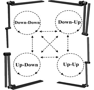
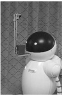
Double Pendulum Robot (Fig. 1) has four equilibrium points: Down-Down, Down-Up, Up-Down, and Up-Up. With these four equilibrium points, 12 transfer actions and 8 circumgyration actions is formed in Fig. 2. The main work of the paper includes: realize these transfer actions and circumgyration actions, and make a random combination of these acrobatic actions (transfer actions and circumgyration actions) to form a sequence of actions and perform these sets of action automatically. Such research result has not been reported. Yamakita [26] has mentioned part of these acrobatic actions, far from the target of arbitrary transfer control of double pendulum, not to mention difficulty actions like DU2UD (transfer from Down-Up to Up-Down).
Fig. 1Double pendulum robot
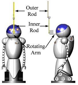
a) The device of Double Pendulum Robot
b) Physical structure
Fig. 2The four equilibrium points of Double Pendulum Robot
2. Mathematic model of Double Pendulum Robot
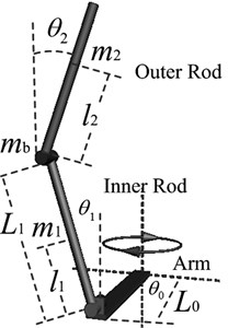
The device of DPR is shown in Fig. 1(a), its prototype is rotary double inverted pendulum, and the physical structure of DPR is shown in Fig. 1(b). The joint between inner rod and outer rod and the joint link inner rod and rotating arm are free link with no drive, and rotating arm (robot body) is driven by the only one input. The angles of both rods and rotating arm are detected by encoders fixed on each joints.
Defining generalized coordinates , applying Lagrange modeling method, and taking angular acceleration of rotating arm as the control variable, the mathematic model can be derived out as follow:
where:
and the physical meaning of each variable is shown in Table 1.
Table 1Physical parameters of Double Pendulum Robot
Parameter | Physical meaning |
, , | Mass of inner rod, outer rod, and encoder |
, | Length of rotating arm, and inner rod |
, | Moment of inertia of inner rod, and outer rod |
, | Centroid position of inner rod, and outer rod |
Friction of arm-inner rod axis | |
Friction of inner rod-outer rod axis | |
Control variable |
3. Challenge of acrobatic actions
The acrobatic actions of DPR are actually the transfer motions from one equilibrium point to another equilibrium point (include the initial equilibrium point). These transfer actions are large-scale nonlinear process and involved variety type of motion form, such as swing up, falling down, and rotating etc. from the energy point of view, transfer actions between equilibrium points means to adjust potential energy of inner rod and outer rod. The single input that imposed on rotating arm can only indirectly manipulate the energy of inner rods and outer rods though the inertia of both rods and the coupling effect of passive joints. Considering the existence of passive joints, the transfer actions can be realized only if the relative attitude (angle and angular velocity) between rotating arm, inner rod, and outer rod is well coordinated and precisely controlled.
Fig. 3The dynamic process of DU2UD
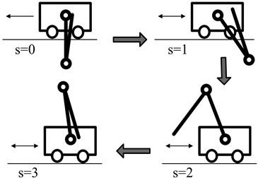
The transfer action of DU2UD (Fig. 3) is considered as a control example for DPR. The initial state is the dynamic balance at Down-Up equilibrium point (inner rod at hanging position and outer rod at inverted position), and the target state is Up-Down equilibrium point. The control target of DU2UD is that: the rotating arm is driven back and forth by an appropriate control input; then, with the effects of inertia and coupling of joints, both rods sing up gradually and eventually reach the dynamic balance at Up-Down equilibrium point (inner rod at inverted position and outer rod at hang position).
The initial state of double pendulum robot is , and the target state is , so the energy transition of DU2UD can be denoted as Eq. (2):
Ignoring the rotational friction of the joints between inner and outer rod, both rods will comply with the momentum conservation law Eq. (3). In order to ensure the success of DU2UD, the relative angle and relative angular velocity between inner rod and outer rod should under the limits of Eq. (4):
4. Control task decomposition and control law determination
It is a hard work to control the Double Pendulum Robot to perform acrobatic actions. According to multi-mode control method of HSIC theory, the first step is to divide the sequence of acrobatic actions into several independent and relatively simple sub-control tasks:
where, is the total control task, is the th variable (degrees of freedom) of control system, is the th sub-control task, is spatial characteristics set for sub-control tasks, is time characteristics set of sub-control tasks, denotes the hierarchical structure that organize these sub-control tasks.
The total control task of transfer action shown in Fig. 2 can be denoted as , while the sub-control task of DU2UD can be denoted as which is under the limitation of Eqs. (2)-(4). Transition from Down-Up to Up-Down is a complex under actuated dynamic process, and such dynamic process can be divided into four phases (Fig. 3). The key to success control of DU2UD is the accurate control of each phase and precise switching between phases.
4.1. Initial control phase
The initial state of DU2UD is dynamic balance at unstable equilibrium point of Down-Up. In order to break this dynamic balance, a simply bang-bang constant would be work; the operation condition of Eq. (6) is shown in Eq. (7):
where, is the angle error of outer rod which takes the Up point (inverted point) as zero error; s is a flag variable to indicate which control phase currently is; is a given constant angle.
The effect of is to break the dynamic balance state at Down-Up equilibrium. When , the next control phase will be triggered (set 1).
4.2. Swing up control phase
The target of this phase is to pump energy into DPR, so both rods can swing up gradually from position below horizontal line to position above horizontal line. A hybrid control combined negative feedback control and positive feedback control is adopted, and the operation condition of swing up control phase is shown in Eq. (9):
where, , , , , , are PD coefficients of rotating arm, inner rod, and outer rod; is angle error of rotating arm; is angle error of inner rod which takes Down point (hanging position) as zero error; is angle error of inner rod which takes Up point (inverted point) as zero; , , are respectively the angular velocity error of rotating arm, inner rod, and outer rod; is a given constant angle. the values of - are carefully selected, and compose a negative feedback control to keep rotating arm in the neighborhood of zero angle, and compose positive feedback control to swing up inner rod gradually, and to make outer rod to keep folded posture corresponding to inner rod.
When that means inner rod has swung up to the position above horizontal line and approaching to the neighborhood of Up point (inverted point), the next phase will be activated (set 2).
4.3. Pose adjustment phase
Pose adjustment phase is activated when inner rod swing up to the neighborhood of inverted equilibrium point. The target of this control phase is to make inner rod keep dynamic balance at upward position and decrease the relative angle between inner rod and outer rod at the same time, so the control low can be designed as follow, and the operation condition of this control phase is shown in Eq. (11):
where, , , , are respectively the PD coefficients of rotating arm and inner rod which make sure rotating arm converges to origin zero angle and inner rod keeps dynamic balance at upward position; constant value which aims to decrease relative angle between inner rod and outer rod is applied according to the rotating direction of outer rod; is the angle amplitude of outer rod which take Down point as zero angle; is a given constant angle.
When that means outer rod convergent to position is near Down point, the next control phase can be activated (set 3).
4.4. Balance control phase
After the effect of previous three phases, DPR swing up to the neighborhood of Up-Down equilibrium point and the target of this phase is to build a new dynamic balance at Up-Down equilibrium point. The control law of Up-Down balance control phase can be designed as follow:
where, , , , , , are respectively the PD coefficients of rotating arm, inner rod, and outer rod. The operation condition of Eq. (11) is shown in Eq. (12):
In summary, the controller of DU2UD can be grouped into Eq. (14):
5. Simulation results
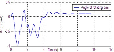
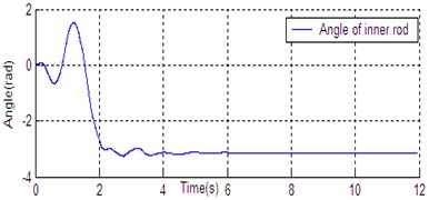
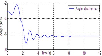
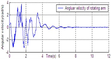
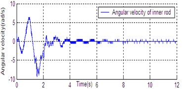
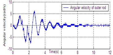
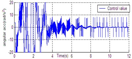
According to the dynamic model (Eq. (1)), the simulation platform of DPR is constructed on the Matlab/Simulink software. The controller (Eq. (14)) is used for DU2UD of DPR, and the parameters of controller are obtained by trial and error. State response of DPR is shown in Fig. 4. Simulation results demonstrate the effectiveness of the proposed algorithm (Eq. (14)).
Fig. 4State response of DU2UD for DPR
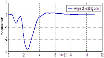
a) Angle of rotating arm
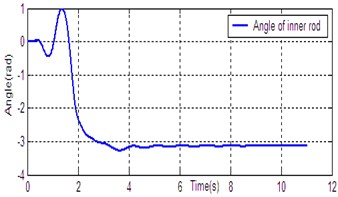
b) Angle of inner rod
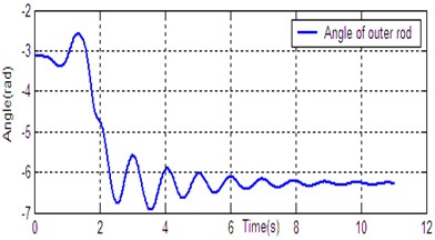
c) Angle of outer rod
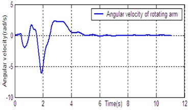
d) Angular velocity of rotating arm
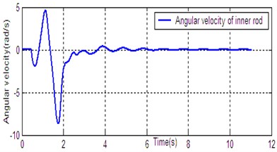
e) Angular velocity of inner rod
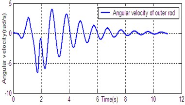
f) Angular velocity of outer rod
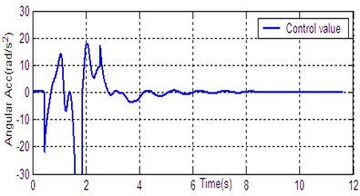
g) Control value
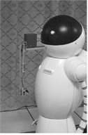
Fig. 5Experimental platform
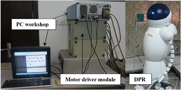
Fig. 6State curve of DU2UD for Double Pendulum Robot
a) Angle of rotating arm
b) Angle of inner rod
c) Angle of outer rod
d) Angular velocity of rotating arm
e) Angular velocity of inner rod
f) Angular velocity of outer rod
g) Control value
6. Experimental results
In Section 4, the control task of Down-Up to Up-Down is divided into four sub-control task, and control law is designed for each sub-control task. The experimental results have been obtained with the Double Pendulum Robot device, which is made up of PC control workshop, motion control PCI card (GT400 from Googol Technology Ltd.) and DPR. The platform of experimental system is shown in Fig. 5. The precision of encoder for rods and servo-motor (Panasonic AC 0.2 Kw, 3000 r/min) respectively are 600 P/R and 2500 P/R. the controller (Eq. (14)) is built with C++ language on PC workshop. Programming environment is Visual C++6.0, operating system is Windows XP, frequency of CPU is 2.66 GHz, the sampling and servo interval is 0.005 s. The state response of DPR is shown in Fig. 6. The timing screenshots from video of DU2UD are shown in Fig. 7. From the experimental results, the same conclusion is obtained with the simulation.
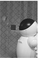
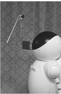
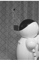
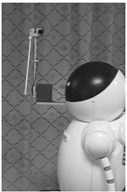
Fig. 7Timing screenshots from real-time video of DU2UD
a) 0.00 s
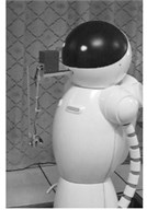
b) 0.44 s
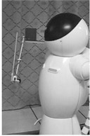
c)0.88 s
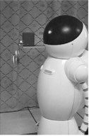
d)1.56 s
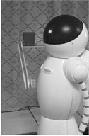
e)1.84 s
f) 2.08 s
g) 2.48 s
h) 2.96 s
i) 3.52 s
j) 6.72 s
7. Conclusions
Based on Human Simulated Intelligent Control theory, the multi-mode control algorithm is proposed for arbitrary transfer control of Double Pendulum Robot. With the transfer action from Down-Up to Up-Down, the simulation and experimental results demonstrate the effectiveness of the multi-mode controller for DPR. Using the same method, other acrobatic actions of Double Pendulum Robot is realized in a short time.
References
-
Hung T. H., Yeh M. F., Lu H. C. A PI-like fuzzy controller implementation for the inverted pendulum system. Proceedings of the IEEE International Conference on Intelligent Processing System, Beijing, China, 1997, p. 218-222.
-
Watts J. W. Control of an inverted pendulum. Proceedings of the ASEE Annual Conference, Salt Lake City, USA, 1984, p. 706-710.
-
Mori S., Nishihara H., Furuta K. Control of unstable mechanical system: control of pendulum. International Journal of Control, Vol. 23, Issue 5, 1976, p. 673-692.
-
Furuta K., Kajiwara H., Kosuge K. Digital control of a double inverted pendulum on an inclined rail. International Journal of Control, Vol. 32, Issue 5, 1980, p. 907-924.
-
Furuta K., Ochia T., Ono N. Attitude control of a triple inverted pendulum. International Journal of Control, Vol. 39, Issue 6, 1984, p. 1351-1365.
-
Yang Ya-Wei, Zhang Ming-Lian The stability of numerical control of triple inverted pendulum. Journal of Beijing University of Aeronautics and Astronautics, Vol. 26, Issue 3, 2000, p. 311-314.
-
Li De-Yi The cloud control of triple inverted pendulum and its dynamic balance mode. Engineering Sciences, Vol. 1, Issue 2, 1999, p. 41-46.
-
Li Hong-Xing, Miao Zhi-Hong, Wang Jia-Yin The adaptive fuzzy control of fourfold inverted pendulum based on variable universe. Science in China (Series E), Vol. 32, Issue 1, 2002, p. 65-75.
-
Wang Peng-Hu, Li Xiao-Bing, Fu Guo-Qing, Wang Qiang The full process variable structure control of 3-stage system. Machinery Design and Manufacture, Vol. 7, 2009, p. 127-129.
-
Astrom K. J., Furuta K. Swinging up a pendulum by energy control. Proceedings of the 13th World Congress, SanFrancisco, USA, 1996, p. 715-720.
-
Muskinja N., Tovornik B. Swinging up and stabilization of a real inverted pendulum. IEEE Transactions on Industrial Electronics, Vol. 53, Issue 2, 2006, p. 631-639.
-
Rubi J., Rubio A., Avello A. Swing-up control problem for a self-erecting double inverted pendulum. IEE Proceedings Control Theory and Applications, Vol. 149, Issue 2, 2002, p. 169-175.
-
Chug C. C., Hauser J. Nonlinear control of a swinging pendulum. Automatica, Vol. 31, Issue 6, 1995, p. 851-862.
-
Li Z. S., Chen Q. C., Li X. M., Inooka H. Human simulating intelligent control and its application to swinging-up of cart-pendulum. Proceedings of the IEEE International Workshop on Robot and Human Communication, Sendai, Japan, 1997, p. 218-223.
-
Li Zu-Shu Swing-up a pendulum with limited torque: the application of human simulating intelligent control on nonlinear system. Control Theory and Applications, Vol. 16, Issue 2, 1999, p. 225-229.
-
Yang J. H., Shim S. Y., Seo J. H., Lee Y. S. Swing-up control for an inverted pendulum with restricted cart rail length. International Journal of Control, Automation and Systems, Vol. 7, Issue 4, 2009, p. 674-680.
-
Park M. S., Chwa D. Y. Swing-up and stabilization control of inverted-pendulum systems via coupled sliding-mode control method. IEEE Transactions on Industrial Electronics, Vol. 56, Issue 9, 2009, p. 3541-3555.
-
Li Zu-Shu, Wang Yu-Xin, Tan Zhi, Zhang Hua, Wen Yong-Lin Swing-up and handstand control of cart double pendulum system and experiment analysis. Proceedings of the 5th World Congress on Intelligent Control and Automation, Hangzhou, China, 2004, p. 2360-2364.
-
Li Zhu-Shu, Tan Zhi, Wang Yu-Xin, Zhang Hua the real-time swing-up and handstand control of cart double pendulum on inclined rail. Proceedings of the 23rd Chinese Control Conference, Wuxi, China, 2004, p. 1645-1649.
-
Li Z. S., Liang D. W. Human simulated intelligent controller with fuzzy online self-tuning of parameters and its application to a cart-double pendulum. Journal of Computers, Vol. 3, Issue 9, 2008, p. 67-76.
-
Liu T. K., Chen C. H., Li Z. S., Chou J. H. Method of inequalities-based multi objective genetic algorithm for optimizing a cart-double-pendulum system. International Journal of Automation and Computing, Vol. 6, Issue 1, 2009, p. 29-37.
-
Graichen K., Treuer M., Zeitz M. Swing-up of the double pendulum on a cart by feedforward and feedback control with experimental validation. Automatica, Vol. 43, Issue 1, 2007, p. 63-71.
-
Devasia S., Chen D. G., Paden B. Nonlinear inversion-based output tracking. IEEE Transactions on Automatic Control, Vol. 41, Issue 7, 1996, p. 930-942.
-
Zhong W., Rock H. Energy and passivity based control of the double inverted pendulum on a cart. Proceedings of the IEEE International Conference on Control Applications, Mexico City, Mexico, 2001, p. 896-901.
-
Li Z. S., Dan Y. H., Wen Y. L., Zhang H., Zhang X. C. Swinging-up and handstand control of cart triple-pendulum system based on HSIC. Proceedings of the 8th IASTED International Conference on Intelligent Systems and Control, Cambridge, ACTA Press, USA, 2005, p. 497-515.
-
Yamakita M., Iwashiro M., Sugahara Y., Furuta K. Robust swing up control of double pendulum. Proceedings of the American Control Conference, Washington, D. C., USA, 1995, p. 290-295.
About this article

This work was supported by Chongqing City Board of Education’s Science and Technology Research Project (KJ130829, KJ130807, KJ1400924) and science and Chongqing Science and Technology Commission’s Technology Personnel Training Program (cstc2013-qnrc40010).
