Abstract
This paper proposes a novel inerter-based component dynamic vibration absorber, namely, electromagnetic resonant shunt tuned mass-damper-inerter (ERS-TMDI). To analyze the performances of the ERS-TMDI, the combined ERS-TMDI and a single degree of freedom system are developed. The norm performances of the ERS-TMDI, whose aim is to minimize the root mean square (RMS) value of structure damage under random ground acceleration excitation, are introduced in comparison with the energy-harvesting series electromagnetic tuned mass dampers (ERS-TMDs), tuned mass-damper-inerter (TMDI) and the classical tuned mass damper (TMD). The closed-form solutions, including the optimal mechanical tuning ratio, the optimal electrical damping ratio, the optimal electrical tuning ratio and the optimal electromagnetic mechanical coupling coefficient, are obtained. It is shown that the ERS-TMDI is superior to both the classical TMD and the ERS-TMD systems for protection from structure damage. Specifically, from the frequency-domain analyses, a case study is performed to illustrate the effectiveness, robustness of the ERS-TMDI and the sensitivity to the parameter changes. From the time-domain analyses, four types of earthquakes are studied to demonstrate the performances of vibration suppression.
1. Introduction
With the development of society, many civil engineering structures have been built, and some of these structures are subjected to dynamic loadings from ground earthquakes. To suppress the vibration, in addition to isolators, the classical Tuned Mass Dampers (TMDs) [1], also called dynamic vibration absorber, is one of the most effective and popular passive vibration mitigation devices in practice, to dissipate the vibration energy [2, 3].
Based on the concept of the classical TMD, various types of TMD have been proposed and optimized [4] by researchers with improved robustness or/and effectiveness of the vibration suppression, such as parallel multiple TMDs [5, 6], series multiple TMDs [7], multi-degree-of-freedom TMDs [8], three or four element TMDs [9], and pounding tuned mass damper [10].
Recently, the inerter, a concept of mechanical network introduced by Smith et al [11, 12], has been adopted from vehicle suspensions for the use in civil engineering for improving the performance of vibration control and displacement mitigation. The inerter produces a proportional force due to the relative acceleration. The inerter has been studied for improvement of car suspensions [13, 14] and railway vehicles [15, 16]. In the past two years, the inerter concept has also been used in proof mass dampers, aiming to improve their damping performance and frequency tunability [17-19], or proof-mass actuation [20] in automotive engineering. In [21], Ikago, et al presented the idea of using an inerter-like ball-screw mechanism in a seismic vibration system with viscous mass damper or tuned viscous mass damper system. A type of electromagnetic inertial mass damper using a ball screw mechanism and a motor was presented to control the vibration of structures subjected to earthquakes in [22]. Lazar, et al. [23, 24] proposed an inerter-based system with a configuration similar to that of a TMD, which is termed as tuned inerter damper (TID), and developed an analytical tuning rule of a TID based on the Den Hartog’s method. Marian and Giaralis [25] also presented the concept of tuned mass-damper-inerter (TMDI) to mitigate the oscillatory motion of support systems which are stochastically excited.
Moreover, the concept of shunting passive damping has been proposed, and initially applied to piezoelectric structures and recently to electromagnetic devices. Forward [26] carried out a preliminary experimental demonstration of the passive circuit shunting for narrow-band reduction of resonant mechanical response. Hagood and Von Flotow [27] theoretically confirmed the possibility that piezoelectric shunted with an RL circuit can serve as a TMD. Behrens et al. [28, 29] extended the idea of a shunt damping to electromagnetic transducer, and obtained the tuning parameters numerically. Inoue, et al [30] obtained closed-form solution with fixed-point method to optimize a one degree of freedom system with an electromagnetic shunt damper. Zuo, et al. studies the energy harvesting from large-scale vibration [31], and proposed the electromagnetic resonant shunt series TMDs (ERS-TMDs) [32], and applied it in the building seismic isolation [33].
Meanwhile, the corresponding closed-form solutions of the optimal design parameters of different TMD systems have been derived. Den Hartog [1] developed the analytical solutions for the TMD for the undamped structures via the fixed-point method. In the [34], simple expressions for optimum absorber parameters of TMD are derived for undamped SDOF systems for harmonic and white noise random excitations. For the TMD with damped primary systems, various design methods and tuning criteria have been raised [35, 36]. Later, Marian and Giaralis [25] developed the optimal TMDI parameters for undamped structures under white noise excitation in closed-form as functions of the TMD mass and the inertance. In the [37], Zuo, et al. proposed the exact solutions of the ERS-TMDs.
Inspired by on the concepts of TMDI [25] and ERS-TMDs [32], this paper proposes a new inerter-based component dynamic vibration absorber, named electromagnetic resonant shunt tuned mass-damper-inerter (ERS-TMDI), in which we replaced the dissipative mechanical element of the TMDI with the electromagnetic transducer shunted with a resonant R-L-C circuit. In addition, this paper derives the closed-form solution of optimal design parameters to the ERS-TMDI for building structures under ground motion. The norm optimal method is employed for the undamped single degree of freedom (SDOF) structure, with the objective to minimize the mean squared value of the displacement of the primary structure. The advantage of the ERS-TMDI will be illustrated through the comparison with the classical TMD, TMDI and ERS-TMDs.
The organization of this paper is as follows. Section 2 describes the governing equations of the SDOF system with ERS-TMDI. Section 3 derives optimal closed-form solutions to the ERS-TMDI systems under the ground motion. In Section 4, the numerical frequency-domain solution of undamped structures is presented in comparison with the classical TMD, TMDI and the ERS-TMDs. In Section 5, the numerical time-domain analysis of damped structures is presented in comparison with classical TMD. Finally, Section 6 concludes this paper.
2. The single degree of freedom system model of the ERS-TMDI
To demonstrate the suppression performance, the main structure is now idealized as a SDOF system modeled using a linear spring of stiffness , a mass , and a damping coefficient , which corresponds to the fundamental mode shape of the multi-story buildings. Fig. 1(b) shows the ERS-TMDs [32] where the foremost energy dissipative damping in classical TMD, depicted in Fig. 1(a), is substituted by an electromagnetic transducer shunted with a coil resistance capacitance and inductance [38, 39]. Inspired by the ERS-TMDs concept, this study considers the ERS-TMDI configuration shown in the Fig. 1(c), in which an inertance is added between the absorber and the fixed ground.
Using similar modeling in [37], the overall dynamic equations of ERS-TMDI, shown in Fig. 1(c), are given by:
Fig. 1Schematic of the coupled SDOF and tuning damper system
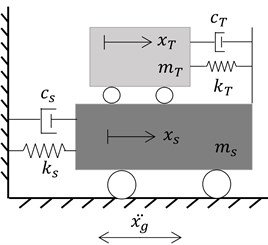
a) Classical TMD
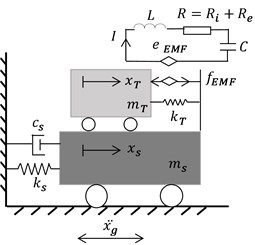
b) ERS-TMD
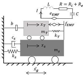
c) ERS-TMDI
When the primary damping , the above can be simplified:
Set , and normalize the frequency, we can have:
Rewrite the relative displacement :
where:
the natural frequency of the main structure ;
the natural frequency of the absorber ;
the resonant frequency of the circuit ;
the mass ratio of the absorber to the main structure ;
the mass ratio of inertance to the main structure ;
the mechanical tuning ratio ;
the electrical tuning ratio ; the normalized frequency ;
the electrical damping ratio of the circuit in which the resistance , is the internal resisitance, and is the external resistance.
The electromagnetic mechanical coupling coefficient , where and is the voltage constant and the force constant of the electromagnetic transducer.
3. optimization for the coupled system
3.1. Vibration control of the ERS-TMDI
Considering the seismic excitation is a random input, the criteriais is more suitable for assessing the system performance for it is RMS value of the performance under unit Gaussian white noise input [37]. This is a good approximation when the earthquake frequency is broad when compared with the natural frequency of the building. To suppress the oscillation of the main structure subjected to the ground acceleration , the criteria are minimized from the ground acceleration to the displacement of the main structure is defined as:
where the symbols and refer to the ensemble and temporal averages, respectively. The performance index represents the ratio of the response of the main system to the seismic excitation with a uniform power spectrum density . Units of the symbols are (m2 s)/rad. The RMS value of the displacementof the SDOF structure can be expressed as:
where is the criteria of the transfer function from the ground acceleration to the displacement of the main structure , where 𝑗 is the unit imaginary number. Substituting Eq. (6) into Eq. (5), the performance index in Eq. (5) can be presented as:
The normalized transfer function can be expressed by using the above dimensionless parameters as:
where:
The integral in Eq. (7) can be solved with the residue theorem [40]. Therefore, the performance index in Eq. (7) can be derived an expression of the four tuning parameters , , , and the three given parameters , , and :
For the purpose of minimizing the performance index concerning the seismic control performance, the derivatives of concerning all the tuning parameters should be equal to zero, wihch mean:
Thereby, the subsequent synchronous gradients’ equations could also be solved from Eq. (10).
To solve this set of equations, by linking Eq. (12d) with the other three equations in Eq. (12), we can remove to acquire a new equation set in other variables , , and . Then with similar handling, the parameters and can also be removed from the new equation set and we can obtain Eq. (12) in only variable . Thus, the optimal parameter can be obtained by Eq. (12) as:
Similarly, the other optimal parameters can be acquired and given as:
where .
Later on, the corresponding optimal absorber stiffness the inductance , and the total resistance can also be presented, involving the above parameters:
While it is the need to declare that the optimal frequency ratio and damping ratio of the criterion for the classical TMD system [1] in Fig. 1(a) is:
And the optimal parameters in the TMDI system [25] are:
where .
Moreover, the optimal parameters for the ERS-TMDs system [37] in Fig. 1(b) are:
In addition, the normalized transfer function from to the relative displacement of the main structure can also be expressed with the above dimensionaless parameters of the ERS-TMDI as:
4. Frequency domain analyses of the ERS-TMDI
4.1. Graphical descriptions of the tuning norms and performance index for seismic control
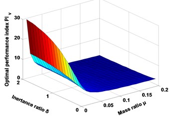
Fig. 2 and Fig. 3 graphically depicts the tuning norms and the optimal index for the seismic control when the main structure is subjected to the seismic excitation. Assuming the mass ratio is certain, when the inertance mass ratio is increasing, the optimal parameters and index are increasing. On the other hand, assuming the inertance ratio is certain, when the mass ratio is increasing, the optimal mechanical tuning ratio , electrical tuning ratio , and index are decreasing, while the others are growing. Finally, when the mass ratio and inertance ratio are increasing simultaneously, the optimal electrical tuning ratio and index are decreasing, while the others are in increasing.
Fig. 2Graphical descriptions of the H2 tuning norms
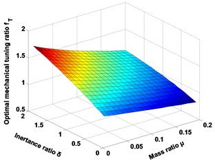
a) Optimal mechanical tuning ratio
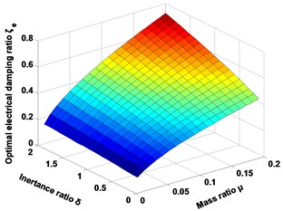
b) Optimal electrical damping ratio
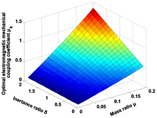
c) Optimal electromagnetic mechanical coupling coefficient
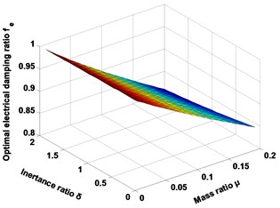
d) Optimal electrical tuning ratio
Fig. 3Schematic of optimal performance index PIv for the seismic control
4.2. Comparing performances of different systems
Fig. 4 show the performances of vibration mitigation of the normalized displacement of the main structure and the relative deformation of five types of SDOF systems, consisting of ERS-TMDI, TMDI, ERS-TMDs, classical TMD, and a system without TMD, which are compared under the same mass ratio of 0.02 in optimal condition with norm. From Fig. 4, the norm of the ERS-TMDI is better than other systems at the same mass ratio. Moreover, it is obvious that the ERS-TMDI has the advantage of suppressing the oscillation of the main structure and relative motion almost across the whole frequency spectrum, in comparison with the others. Particularly, at their own resonant frequencies, the spiked value of the normalized displacement of the main structure in the ERS-TMDI system is decreased by around 36 % in comparison with the classical TMD, 23 % with the TMDI and 18 % with the ERS-TMDs. In addition, when the frequency is ranging from 0.7 to 1.3, the area of the of the ERS-TMDI is decreased by about 9 % compared to the classical TMD, 4 % to that of the TMDI and 6 % to that of the ERS-TMDs.
Fig. 4Schematic of the optimal frequency responses for types of SDOF system, where the mass ratio μ= 0.02
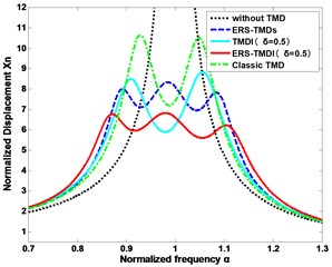
a) The deformation of the main structure
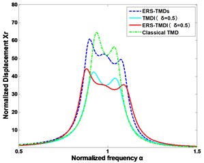
b) The relative deformation of the damper
4.3. Comparing performances of the ERS-TMDI under different inertance ratios
The performances of vibration mitigation of the displacement of the main structure and the relative displacement of the ERS-TMDI are compared under different inertance ratios. From Fig. 5, the norm of the ERS-TMDI is better at the highest inertance ratio.
Fig. 5Schematic of the optimal frequency responses for types of SDOF system under different inertance ratios
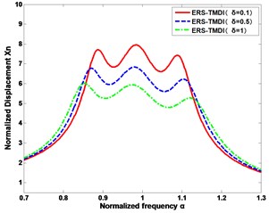
a) The deformation of the main structure
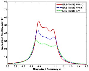
b) The relative deformation of the damper
4.4. Sensitivity of tuning parameters
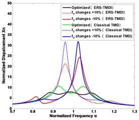
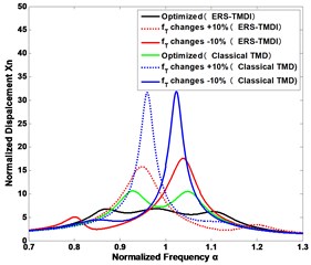
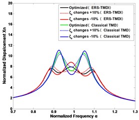
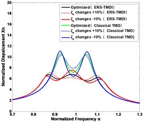
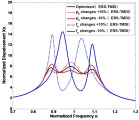
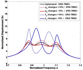
In practice, it is a challenge to tune the parameters faultlessly, since some parameters may vary after some time. Fig. 6 shows how the seismic control performance will change with the variations of the tuning parameters for the ERS-TMDI system at the different inertance ratios under a ground excitation, as compared with classical TMD. It is clear that the mechanical tuning ratio , is the most susceptive design parameter to the seismic control, while the electrical damping ratio , is the least susceptive to the seismic control. Besides, when the inertance ratio is increasing, the ERS-TMDI is more robust to the parameter changes. In addition, we can also draw the conclusion that the tuning parameters of classic TMD is more sensitive than that of the ERS-TMDI.
Fig. 6The sensitivity of vibration suppression to the changes of the design parameters of the ERS-TMDI and classical TMD: mechanical tuning ratio fT of a) the inertance ratio δ= 0.1 and b) the inertance ratio δ= 0.5; the electrical damping ratio ζe of c) the inertance ratio δ= 0.1 and d) the inertance ratio δ= 0.5; the coupling coefficient μk and electrical tuning ratio fe of e) the inertance ratio δ= 0.1 and f) the inertance ratio δ= 0.5
a)
b)
c)
d)
e)
f)
5. Time-domain analyses of the ERS-TMDI
5.1. Mathematical model
In Section 5, the time-history responses of the model demonstrated above are computed for four simulated earthquakes based on observed earthquake records in order to prove the effect of the ERS-TMDI. The equations of motion for the system of ERS-TMDI are simply described as a three-degree-of-freedom system, as shown in Eq. (1). Therefore, matrix representations of the equations of motion are useful for estimating the time-history responses. The equations of motion for the ERS-TMDI can be formulated as follows:
Eq. (1) can be expressed in second order form:
Set , Eq. (20) can also be written in a matrix form:
where:
Define , then the state space equation is:
where:
5.2. Simulation parameters
To facilitate the simulation analysis of ERS-TMDI, the performances of ERS-TMDI are compared with that of the Classical TMD in the optimal condition. The fundamental modal shape corresponding to ten-story frame buildings and Table 1 shows the parameters of the combined system in the numerical simulations.
Table 1The parameters of simulation
Description | Symbol | Value |
Main structure mass | 58970 [kg] | |
Stiffness coefficient of the main structure | 4.81104 [kN/m] | |
The fundamental period of the main structure | 0.22 [s] | |
Damping of the main structure | 67.4 [kN s/m] | |
Inertance mass | 589.7 [kg] | |
Stiffness coefficient of the mechanical TMD | 1.35103 [kN/m] | |
Mechanical TMD mass | 1179 [kg] | |
Grossinductance of electrical transducer | 30.6 [mH] | |
Gross capacitance of electrical transducer | 41.6 [mF] | |
Internal resistance of motor | 0.13 [Ω] | |
External resistance | 0.13 [Ω] | |
The constant of the electromagnetic actuator | , | 50 |
5.3. The performance of seismic control
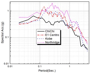
Time-history analyses are performed by numerical integration using the Newmark’s method, with a time interval of 0.01 s and the adjusted maximum earthquake acceleration of 200 cm/s2 to compare the performance with the different records. The observed earthquake records used for applying the ground acceleration to the models are as follows: (1) ChiChi, (2) El Centro, (3) Kobe, and (4) Northridge. The time histories of the earthquake records are shown in Fig. 7. The elastic acceleration response spectra of the earthquakes are also shown in Fig. 8, in which we can know the predominant periods of the selected earthquakes from the response spectra. In the time-history analyses, the characteristics of the model are identical to those used in the frequency-domain analyses described Section 4.
Fig. 7Time histories showing observed earthquake records used for time-history analyses

a) ChiChi

b) El Centro

c) Kobe

d) Northridge
Fig. 8Response spectra for observed earthquake records
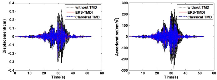
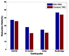
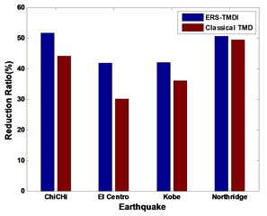
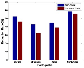
From Fig. 9 to Fig. 11, on the whole, it is clear that the ERS-TMDI effectively reduces the peak and root mean square (RMS) value of the displacement of the main structure, especially for the case of Northridge, which contains strong long-period components. It is also noted that the performance of the vibration mitigation of the ERS-TMDI is clearly superior to that of the classical TMD.
Fig. 9Time-history diagram of displacements (left) and accelerations (right) of the main structure: comparison between classical TMD and ERS-TMDI excited
a) ChiChi
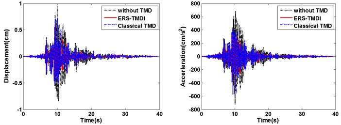
b) El Centro
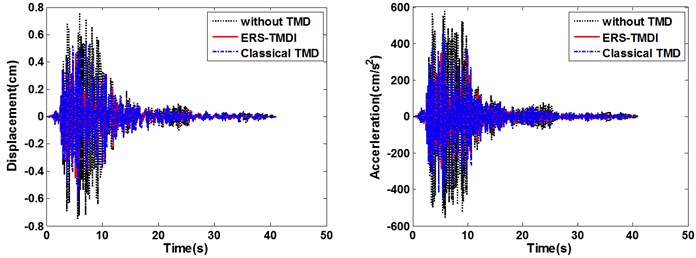
c) Kobe
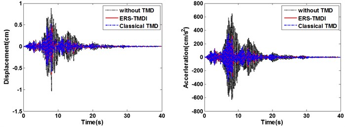
d) Northridge
Fig. 10Reduction ratio related to a) response peak displacement and b) response peak acceleration of classical TMD system and ERS-TMDI system
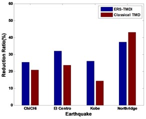
a)
b)
Fig. 11Reduction ratio related to a) response RMS value of displacement and b) response RMS value of acceleration of classical TMD system and ERS-TMDI system
a)
b)
6. Conclusions
This paper investigates electromagnetic resonant shunt tuned mass-damper-inerter (ERS-TMDI) system, which consists of an auxiliary mechanical mass, an inertance mass, a spring, and an electromagnetic shunted RLC. We derive tuning laws on a SDOF system, with the physical meaning to reduce the RMS value of the displacement of the main structure subjected to random acceleration excitation from the base. Later on, both frequency-domain and time-domain analyses are studied to demonstrate the performance of vibration mitigation.
The frequency-domain analyses show that the ERS-TMDI can enhance efficiency of seismic control due to tuning both the resonances of the mechanical mass, the inertance, and the electrical resonator, in comparison with classical TMD, where only the mechanical resonance is tuned. Particularly, the ERS-TMDI of mass ratio 0.02 and inertance ratio 0.5 improves the vibration suppression by reducing the resonant peak value of displacement of main structure by around 36 % compared to that of the classical TMD, 23 % to the TMDI and 18 % to the ERS-TMDs, and the area of by around 9 %, 4 %, 6 %. In addition, the performances of vibration mitigation of the oscillation of the main structure and the deformation of the ERS-TMDI are better at the higher inertance ratio. And compared with classical TMD, the system is more robust to the off tuning or parameter changes.
The time-domain analyses show that the ERS-TMDI effectively reduces the peak and RMS value of the displacement of the main system, especially for the case of Northridge. It is also noted that, in the performance of the vibration mitigation, the ERS-TMDI is superior to the classical TMD.
References
-
Hartog J. P. D. Mechanical Vibration. 1956.
-
Housner G. W., Bergman L. A., Caughey T., Chassiakos A., Claus R., Masri S., Skelton R., Soong T., Spencer B., Yao J. T. Structural control: past, present, and future. Journal of Engineering Mechanics, Vol. 123, Issue 9, 1997, p. 897-971.
-
Soong T., Spencer B. Supplemental energy dissipation: state-of-the-art and state-of-the-practice. Engineering Structures, Vol. 24, Issue 3, 2002, p. 243-259.
-
Den Hartog J. P. Mechanical Vibrations. Courier Corporation, 1985.
-
Xu K., Igusa T. Dynamic characteristics of multiple substructures with closely spaced frequencies. Earthquake Engineering and Structural Dynamics, Vol. 21, Issue 12, 1992, p. 1059-1070.
-
Yamaguchi H., Harnpornchai N. Fundamental characteristics of multiple tuned mass dampers for suppressing harmonically forced oscillations. Earthquake Engineering and Structural Dynamics, Vol. 22, Issue 1, 1993, p. 51-62.
-
Zuo L. Effective and robust vibration control using series multiple tuned-mass dampers. Journal of Vibration and Acoustics, Vol. 131, Issue 3, 2009, p. 837-838.
-
Lei Zuo, Samir Nayfeh Design of multi-degree-of-freedom tuned-mass dampers: a minimax approach. Proceedings of SPIE, Vol. 4697, Issues 3-5, 2003, p. 98-108.
-
Snowdon J. C. Dynamic vibration absorbers that have increased effectiveness. Journal of Manufacturing Science and Engineering, Vol. 96, Issue 3, 1974, p. 940-945.
-
Li H., Zhang P., Song G., Patil D., Mo Y. Robustness study of the pounding tuned mass damper for vibration control of subsea jumpers. Smart Materials and Structures, Vol. 24, Issue 9, 2015, p. 095001.
-
Smith M. C. Synthesis of mechanical networks: the inerter. IEEE Transactions on Automatic Control, Vol. 47, Issue 10, 2002, p. 1648-1662.
-
Chen M. Z., Papageorgiou C., Scheibe F., Wang F.-C., Smith M. C. The missing mechanical circuit element. IEEE Circuits and Systems Magazine, Vol. 9, Issue 1, 2009, p. 10-26.
-
Smith M. C., Wang F.-C. Performance benefits in passive vehicle suspensions employing inerters. Vehicle System Dynamics, Vol. 42, Issue 4, 2004, p. 235-257.
-
Hu Y., Chen M. Z., Shu Z. Passive vehicle suspensions employing inerters with multiple performance requirements. Journal of Sound and Vibration, Vol. 333, Issue 8, 2014, p. 2212-2225.
-
Jiang J. Z., Matamoros-Sanchez A. Z., Goodall R. M., Smith M. C. Passive suspensions incorporating inerters for railway vehicles. Vehicle System Dynamics, Vol. 50, 2012, p. 263-276.
-
Wang F.-C., Liao M.-K., Liao B.-H., Su W.-J., Chan H.-A. The performance improvements of train suspension systems with mechanical networks employing inerters. Vehicle System Dynamics, Vol. 47, Issue 7, 2009, p. 805-830.
-
Hu Y., Chen M. Z. Performance evaluation for inerter-based dynamic vibration absorbers. International Journal of Mechanical Sciences, Vol. 99, 2015, p. 297-307.
-
Brzeski P., Pavlovskaia E., Kapitaniak T., Perlikowski P. The application of inerter in tuned mass absorber. International Journal of Non-Linear Mechanics, Vol. 70, 2015, p. 20-29.
-
Krenk S., Høgsberg J. Tuned resonant mass or inerter-based absorbers: unified calibration with quasi-dynamic flexibility and inertia correction. Proceedings of the Royal Society of London A: Mathematical, Physical and Engineering Sciences, 2016, p. 20150718.
-
Zilletti M. Feedback control unit with an inerter proof-mass electrodynamic actuator. Journal of Sound and Vibration, Vol. 369, 2016, p. 16-28.
-
Ikago K., Saito K., Inoue N. Seismic control of single-degree-of-freedom structure using tuned viscous mass damper. Earthquake Engineering and Structural Dynamics, Vol. 41, Issue 3, 2012, p. 453-474.
-
Nakamura Y., Fukukita A., Tamura K., Yamazaki I., Matsuoka T., Hiramoto K., Sunakoda K. Seismic response control using electromagnetic inertial mass dampers. Earthquake Engineering and Structural Dynamics, Vol. 43, Issue 4, 2014, p. 507-527.
-
Lazar I. F., Neild S. A., Wagg D. J. Using an inerter-based device for structural vibration suppression. Earthquake Engineering and Structural Dynamics, Vol. 43, Issue 8, 2014, p. 1129-1147.
-
Lazar I. F., Neild S. A., Wagg D. J. Vibration suppression of cables using tuned inerter dampers. Engineering Structures, Vol. 122, 2016, p. 62-71.
-
Marian L., Giaralis A. Optimal design of a novel tuned mass-damper-inerter (tmdi) passive vibration control configuration for stochastically support-excited structural systems. Probabilistic Engineering Mechanics, Vol. 38, 2014, p. 156-164.
-
Forward R. L. Electronic damping of vibrations in optical structures. Applied Optics, Vol. 18, Issue 5, 1979, p. 690-697.
-
Hagood N. W., Flotow A. V. Damping of structural vibrations with piezoelectric materials and passive electrical networks. Journal of Sound and Vibration, Vol. 146, Issue 2, 1991, p. 243-268.
-
Behrens S., Fleming A. J., Moheimani S. O. R. Electromagnetic shunt damping. IEEE/ASME International Conference on Advanced Intelligent Mechatronics, Vol. 1142, 2003, p. 1145-1150.
-
Behrens S., Fleming A. J., Moheimani S. O. R. Passive vibration control via electromagnetic shunt damping. IEEE/ASME Transactions on Mechatronics, Vol. 10, Issue 1, 2005, p. 118-122.
-
Inoue T., Ishida Y., Sumi M. Vibration suppression using electromagnetic resonant shunt damper. Journal of Vibration and Acoustics, Vol. 130, Issue 4, 2008, p. 2727-2747.
-
Zuo L., Tang X. Large-scale vibration energy harvesting. Journal of Intelligent Material Systems and Structures, Vol. 24, Issue 11, 2013, p. 1405-1430.
-
Zuo L., Cui W. Dual-functional energy-harvesting and vibration control: electromagnetic resonant shunt series tuned mass dampers. Journal of Vibration and Acoustics, Vol. 135, Issue 5, 2013, p. 510181-510189.
-
Cao M. Energy harvesting from building seismic isolation with multi-mode resonant shunt circuits. ASME 2014 Dynamic Systems and Control Conference, 2014, p. V002T032A001.
-
Warburton G. B. Optimum absorber parameters for various combinations of response and excitation parameters. Earthquake Engineering and Structural Dynamics, Vol. 10, Issue 3, 1982, p. 381-401.
-
Sadek F., Mohraz B., Taylor A. W., Chung R. M. A method of estimating the parameters of tuned mass dampers for seismic applications. Earthquake Engineering and Structural Dynamics, Vol. 26, Issue 6, 1997, p. 617-635.
-
Tsai H. C., Lin G. C. Optimum tuned-mass dampers for minimizing steady-state response of support-excited and damped systems. Earthquake Engineering and Structural Dynamics, Vol. 22, Issue 11, 1993, p. 957-973.
-
Liu Y., Lin C.-C., Parker J., Zuo L. Exact h2 optimal tuning and experimental verification of energy-harvesting series electromagnetic tuned-mass dampers. Journal of Vibration and Acoustics, Vol. 138, Issue 6, 2016, p. 061003.
-
Tang X., Zuo L. Simultaneous energy harvesting and vibration control of structures with tuned mass dampers. Journal of Intelligent Material Systems and Structures, Vol. 23, Issue 18, 2012, p. 2117-2127.
-
Lefeuvre E., Audigier D., Richard C., Guyomar D. Buck-boost converter for sensorless power optimization of piezoelectric energy harvester. IEEE Transactions on Power Electronics, Vol. 22, Issue 5, 2007, p. 2018-2025.
-
Gradshteyn I., Ryzhik I. Table of Integrals Series and Product. Academic Press, 1980.
About this article
This work was supported by National Key Basic Research Scheme of China (973 Program) under Grant 2015CB057702, National Natural Science Foundation of China under Grant 51508185 and 51378203, and Natural Science Foundation of Hunan Province of China under Grant 2015JJ3073. The author Hongxin Sun is also grateful to the financial support from China Scholarship Council to conduct research as a visiting scholar in Lei Zuo’s Lab at Virginia Tech.
