Abstract
It is difficult for the robot to grasp objects of any pose by the independent grasping scheme without the help of human. And the independent grasping scheme is also the key technology to develop the AI robot. In order to solve the problem, this paper establishes the full 3D point cloud model of the target object in advance under the PCL point cloud library. The partial view model of the target object in the current working environment is extracted when dexterous hand grasps the target. After aligning the extracted partial view model, the best alignment homogeneous transformation matrix mapping the partial view model to the full 3D point cloud model is obtained. According to the inverse matrix of the obtained matrix, the 3D point cloud model of the target object in the current working environment, where dexterous hand grasps the target, is obtained through the homogeneous transformation. According to the characteristics of the dexterous hand, a grasping algorithm is proposed, which is suitable for the most objects. Finally, the algorithm is verified by the point cloud model of the target object, and finds out the grasping points and grasping pose accurately (the direction of the hand's force). It demonstrates that this algorithm is correct and useful.
1. Introduction
Robot with the ability of the independent grasping scheme is so versatile, such as space exploration, industrial production and household services [1-3]. So independent grasping scheme is the key technology to develop the AI robot and needs to be solved urgently. The independent grasping of the dexterous hand firstly imitates the eye of human to analyze the pose and shape of the object. And then it imitates the hand to grasp the object. However, according to the fact that the usage of human vision and hand occupies at least 70 percent of the human brain resources, the independent grasping scheme is considered as AI-complete problems in academic circles [4].
The independent grasping scheme is divided into 3 steps. Firstly, the full 3D point cloud model of the object is established and stored in dexterous hand system in advance. Secondly, it extracts the partial view model of the target object in the current working environment, and maps the full 3D point cloud model to the current position. Finally, after the pose and shape of the object is analyzed, the grasping points and the grasping pose are obtained. Nguyen [5-6] proposed a force closure algorithm based on the shape of the object. It estimates the independent region of the contact through the force closure grasp, and then the motion of the object is completely restrained. Through the study and preservation of the past experience, the mechanism of extracting the effective grasping plan is established [7]. Phoka [8] utilized the genetic algorithm to design a new grasping planner for the object, which can plan the optimized grasping mode under certain conditions. Li Jiawei [9] studied a force closure grasp of three fingers. And he also studied the optimal minimum internal force required for the stabilization grasp when external interference is existed.
In order to grasp the object in the space station, an independent planning algorithm for the grasping point and grasping pose of the object is proposed. At last, the algorithm is verified by the point cloud model of the target object, and the algorithm finds out the grasping points and grasping pose accurately.
2. Establish the target model
To establish the 3D point cloud model of the target object, the partial view models of the object need to be scanned from multiple viewpoints. Then, the partial view models are integrated into the full 3D point cloud model. This paper uses the Microsoft KINECT V2 sensor to scan the surface of the target object. Each coordinate origin of the six sensors is respectively located in center of the six surfaces of the virtual cube with the 1.6 m side. The coordinates of the six sensors are respectively named {A}, {B}, {C}, {D}, {E} and {F} (Fig. 1). Where the , and axis of the coordinate system {B} are respectively corresponding to the , and axis of the coordinate system {A}. The coordinate system {A} is chosen as the world coordinate system. The partial view models in the other five coordinates are transformed to the world coordinate system through the homogeneous transformation. And then, the full 3D point cloud model of the object is obtained. There are the following formulas:
where is the point in the coordinate system {A}, is the point in the coordinate system {B}, is the homogeneous transformation matrix mapping the coordinate system {B} to the coordinate system {A}, , and are the angles around , and axes of the coordinate system {A} respectively, , and are the translation distance in the coordinate system {A}. The homogeneous transformation matrix can be obtained:
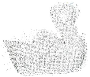
The homogeneous transformation matrix mapping the other coordinates system to the coordinate system {A} can be deduced by the same method. After all homogeneous transformation, the full 3D point cloud model of the target object can be obtained (Fig. 2).
Fig. 1Six sensors installation position
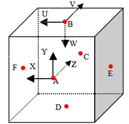
Fig. 23D point cloud model
3. The target model alignment
Robot can generally see the partial view like human. When the robot recognizes the partial view of the target object, the full 3D point cloud model which is established in section 2 needs to be mapped to the current working position for grasping the object. FPFH descriptor and the Sample Consensus Initial Alignment algorithm will be used [10]. FPFH descriptor is a novel representation for object features. The FPFH includes the relative pan angle , tilt angle and yaw angle (Fig. 3).
Fig. 3Schematic diagram of each angle

Fig. 4Influence area of the picked point
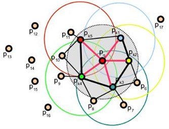
Where and are two points in the point cloud model, and are respectively the normal of and . Defining a Cartesian coordinate system, where is a unit vector with the same direction of and is a unit vector with the same direction of and is a unit vector with the same direction of . So there are the following formulas:
where , and between the picked point and other points in the influence area of the picked point are computed (Fig. 4), which is called the Simplified Point Feature Histogram (SPFH). Then:
where is the number of points in the influence area of , is the point in the influence area of , is the distance from to .
The Sample Consensus Initial Alignment algorithm can accomplish the mapping from the partial view of the target object in the current working environment to the full 3D point cloud model. The steps are as follows:
Select sample points from the partial view while making sure that their pairwise distances are greater than a user-defined distance.
For each of the sample points, find a list of points in the full 3D point cloud model whose FPFH descriptors are similar to the sample points’ FPFH descriptors. From these, select one randomly which will be considered that sample points’ correspondence.
Compute the rigid transformation defined by the sample points and their correspondences and compute an error metric for the point cloud that computes the quality of the transformation.
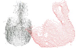
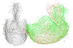
These three steps are repeated, and the homogeneous transformation matrix that yielded the minimum error metric is stored and used to roughly align the partial views. According to the inverse of the stored matrix, the 3D point cloud model of the target object in the current working environment is obtained after the homogeneous transformation. Thus, the full 3D point cloud model of the object in the current working environment is obtained through the partial view (Fig. 5).
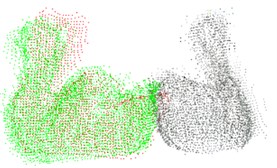
Where the gray point cloud is the full 3D point cloud of the target object established in Section 2. The red point cloud is the partial view of the object in the current working environment. The green point cloud is the result of the 3D point cloud model mapped to the partial view in the current environment by the Sample Consensus Initial Alignment algorithm. And the green point cloud is considered as the full 3D point cloud model of the object in the current working environment.
Fig. 5Point cloud model: a) the full 3D point cloud model and partial view of the target object before alignment, b) result obtained after alignment, c) observation from another viewpoint
a)
b)
c)
4. The grasping algorithm and verification
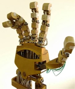
Due to working in the weightless space station, the gravity is not considered. The structure of the dexterous hand is similar to the human hand (Fig. 6). The grasping mode can be classified as the power grasp and the precision grasp. The precision grasp selects the grasping points on the target object and plans the grasping pose according to the pose and shape of the object. According to the grasping feature, this paper considers the thumb finger as one grasping point, and the other four fingers as one. So the fine grasp will be simplified as two grasping points, which are called the grasping point pair in this paper.
Fig. 6NUAA hand
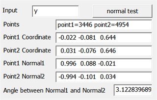
It needs to ensure that the two force are the same size and the opposite direction for grasping the object. Because of the friction, the angle between the direction of two force should be more than a certain value. This paper considers that the angle is more than 3.12 Rad (178.8 degrees), which meets the requirements. By the simplified model, a grasping algorithm is proposed. The main steps are as follows:
1) Select one point from the full 3D point cloud called , and compute the normal of .
2) The point and its normal form a line , and find out those points which are a user-defined value away from the line . This value is set to 1.5 times the resolution of the point cloud that make sure those points in line .
3) Compute the normal of each point from those found points, and find out the point called . The angle between the normal of point and the normal of point is closest to . This angle is called in this paper. Point and point are the grasping point pair.
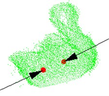
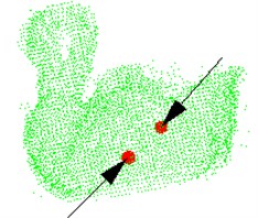
These three steps are repeated for each point in the 3D point cloud model. And the grasping point pair that yielded the maximum is stored. The two points in the stored grasping point pair are considered as the grasping points of the target object, and the normal of the two points is the grasping pose. The algorithm is verified by the green point cloud model in Section 3, and the results are shown in Fig. 7.
Fig. 7The green point cloud model: a) grasping point and pose, b) observation from another viewpoint, c) the parameters are obtained after testing the model
a)
b)
c)
Where Fig. 7(a) and Fig. 7(b) are the different visions of the target object. The red balls are the grasping points, and the black arrows are the grasping pose. The parameters are obtained after testing the model, as shown in (c), including the sequence of the grasping points in point cloud, points’ coordinates, normal of the point and angle between two normal.
5. Conclusions
Firstly, six partial views of the target object are integrated into one point cloud through the homogeneous transformation. Thus, the full 3D point cloud model of the target object is established in advance. Secondly, according to the partial view of the object in the current working environment, the full 3D point cloud model of the object in the current working environment is obtained through FPFH descriptor and the Sample Consensus Initial Alignment algorithm. Thirdly, a grasping algorithm is proposed. The algorithm is verified by the point cloud model of the target object, and finds out the grasping points and grasping pose accurately. It demonstrates that this algorithm is suitable for the most objects. This algorithm can also determine whether the point cloud model of the object can be grasped by the dexterous hand.
However, the grasping algorithm is just applied to the condition without gravity and obstacle. If this algorithm will be used in the complex environment on the ground, the gravity and obstacles must be considered. In the future, further studies will be launched.
References
-
Bluethmann W., Ambrose R., Diftler M., Askew S., et al. Robonaut: a robot designed to work with humans in space. Autonomous Robots, Vol. 14, Issues 2-3, 2003, p. 179-197.
-
Okita S. Y., Ng-Thow-Hing V., Sarvadevabhatla R. Learning together: ASIMO developing an interactive learning partnership with children. The 18th IEEE International Symposium on Robot and Human Interactive Communication, 2009, p. 1125-1130.
-
Chen J. B., Han D., Peng Z. Active grasping control of virtual-dexterous-robot hand with open inventor. Mathematical Problems in Engineering, Vol. 65, Issue 1, 2014, p. 82-87.
-
Wu Y. G., Qian J. W. A survey of grasp synthesis method of dexterous hand. China Mechanical Engineering, Vol. 15, Issue 3, 2004, p. 276-281.
-
Nguyen V. D. Constructing force-closure grasps. International Journal of Robotics Research, Vol. 3, Issue 3, 1986, p. 1368-1373.
-
Nguyen V. D. The synthesis of stable grasps in the plane. IEEE International Conference on Robotics and Automation, 1985, p. 884-889.
-
Morales A., Asfour T., Azad P., et al. Integrated grasp planning and visual object localization for a humanoid robot with five-fingered hands. International Conference on Intelligent Robots and Systems, 2006, p. 5663-5668.
-
Phoka T., Niparnan N., Sudsang A. Planning optimal force-closure grasps for curved objects by genetic algorithm. IEEE Conference on Robotics, Automation and Mechatronics, 2007, p. 1-6.
-
Li J. W., Hu H. Y., Wang B., et al. Simple algorithm for internal force of multiple fingers grasping. Progress in Natural Science, Vol. 15, Issue 6, 2005, p. 733-738.
-
Rusu R. B., Blodow N., Beetz M. Fast Point Feature Histograms (FPFH) for 3D registration. IEEE International Conference on Robotics and Automation, 2009, p. 3212-3217.
About this article

This study was co-supported by the NUAA Fundamental Research Funds for the Central Universities (No. NS2015085).
