Abstract
Ancient buildings carry important information, such as ancient politics, economy, culture, customs. However, with the course of time, ancient buildings are often damaged to different degrees, so the restoration of ancient buildings is of great importance from the historical point of view. There are three commonly used non-contact measurement methods, including UAV-based oblique photogrammetry, terrestrial laser scanning, and close-range photogrammetry. These methods can provide integrated three-dimensional surveys of open spaces, indoor and outdoor surfaces for ancient buildings. Theoretically, the combined use of the three measurement methods can provide 3D (three-dimensional) data support for the protection and repair of ancient buildings. However, data from the three methods need to be fused urgently, because if the image data is not used, it will lead to a lack of real and intuitive texture information, and if only image matching point clouds are used, their accuracy will be lower than that of terrestrial laser scanning point clouds, and it will also lead to a lack of digital expression for components with high indoor historical value of ancient buildings. Therefore, in this paper, a data fusion method is proposed to achieve multi-source and multi-scale 3D data fusion of indoor and outdoor surfaces. It takes the terrestrial laser point cloud as the core, and based on fine component texture features and building outline features, respectively, the ground close-range image matching point cloud and UAV oblique image matching point cloud are registered with the terrestrial laser point cloud. This method unifies the data from three measurements in the point cloud and realizes the high-precision fusion of these three data. Based on the indoor and outdoor 3D full-element point cloud formed by the proposed method, it will constitute a visual point cloud model in producing plans, elevations, sections, orthophotos, and other elements for the study of ancient buildings.
Highlights
- Multi-source 3D data collection and preprocessing for ancient buildings
- Based on fine component texture features and building outline features to realize the coarse registration
- Automatic fine registration and accuracy analysis
1. Introduction
The ancient architectural heritage represents an important part of our country’s history and culture. The effective protection and rational reuse of the ancient architectural heritage are of far-reaching significance to the inheritance of the traditional culture of the Chinese nation and the promotion of cultural exchanges between different nationalities. With the rapid development of 3D (three-dimensional) digitization, the protection of ancient buildings has gradually changed from traditional to digital auxiliary way. Precise digital data can help relevant practitioners to build up decision-making plans on protection and repair, which also can further promote the scientific development of ancient architectural cultural heritage protection.
Currently, non-contact measurement instruments such as 3D laser scanners, Unmanned Aerial Vehicle (UAV) equipment, and Single Lens Reflex (SLR) cameras are undergoing a transition from “professional level” to “consumer level” thus gradually participating in the informatization construction process. This can be useful for the architectural heritage protection, 3D urban modeling, transmission line maintenance, vegetation classification, etc., and makes the acquisition of high-resolution 2D (two-dimensional) images and accurate 3D point clouds more efficient and convenient [1]. For the three multi-source heterogeneous data of terrestrial laser point cloud, oblique image, and ground close-range image [2], five aspects such as collection method, collection efficiency, collection requirements, advantages, and disadvantages are compared in Table 1 [3]. Among them, the multi-source heterogeneous data can reflect the surface features of the target object, but when the terrestrial laser scanning equipment is used to scan the target object, it tends to be hampered by the obstruction of the line of sight and the limitation of the scanning angle of the equipment. So that each scan can only reflect a part of the point cloud of the target object. UAV oblique photography and digital close-range photogrammetry can quickly capture the spectrum, relative position, and status of an object without contacting the target to be measured by setting the parameters of a non-measurement digital camera, and 3D scenes recorded by the camera's built-in sensor can be projected onto photos. The point cloud obtained by the image dense matching technology is the reverse reasoning of the above process, and the image matching point cloud is rich in texture with obvious edge features, which can restore the 3D scene more effectively [4]-[5]. The different processing software used for image reconstruction are popular in different countries: ContextCapture in the United States, Pix4Dmapper in Switzerland, Agisoft Photoscan in Russia, Lensphoto and VirtuoZo in China, etc., but the basic operation principle is almost the same and roughly composed of sparse point cloud reconstruction, dense point cloud reconstruction, point cloud mesh modeling, 3D semantic modeling, 3D vector modeling, texture mapping, etc. However, when the overlap between the images is not enough or the target object is occluded, then the image matching point cloud obtained by matching may have point cloud holes or point cloud blocks that do not match the actual ones at the corresponding position. At the same time, due to the robustness of the matching algorithm, the dense point cloud obtained by matching often cannot achieve full coverage description.
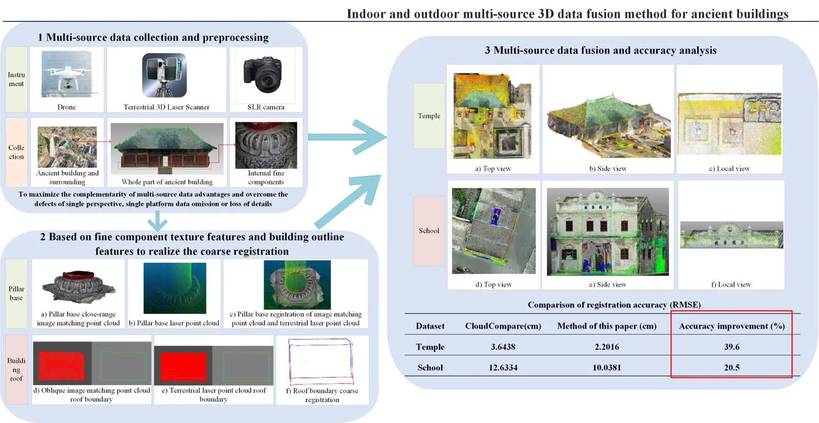
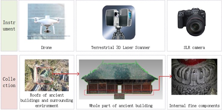
In order to maximize the complementarity of point cloud advantages and overcome the defects of single perspective, single platform data omission or loss of details, it is necessary to integrate cross-platform point clouds, so as to achieve a full range of spatial information expression in the target area [6], as well as a complete and detailed description of the digital reality of a wide range of scene [6]-[8]. Therefore, based on the existing equipment and related research, this paper proposes to use a variety of surveying and mapping instruments such as drones, terrestrial laser scanners, and SLR cameras to complete the digital acquisition as shown in Fig. 1. Compared with the previous single digital acquisition technology, this method not only greatly improves the efficiency of data acquisition, but also enables a fused multi-level detail model [3] to have both multiple advantages such as obvious oblique image texture details, high accuracy of 3D laser cloud points, rich spectral information of close-range images, etc. For the collected multi-source and multi-scale data, this paper firstly converts large-scene oblique images and small-scene ground close-range images into the color point clouds based on the image dense matching technology. And then it uses the terrestrial laser point cloud as the intermediate fusion medium, respectively based on the building outlines and the point cloud point features, the image matching point clouds of two sets of different volume scenes are registered with the terrestrial laser point cloud to achieve fusion. Finally, the point cloud data formed by the fusion of multi-source heterogeneous data can improve the accuracy, density, reliability, integrity, and geographic reference quality of 3D scene data [3], as well as provide accurate digital support, model reference from perspective, and scientific substantiation for restoration workers, and then foster the development of the actual repair work in the later period.
Table 1Comparison of three types of measurement methods
Data | Measurement method | Collection efficiency | Collection requirements | Fineness | Advantages | Disadvantages |
Terrestrial laser point cloud | Laser | High | Overlap | High | Big amount of data Less affected by the weather Accurately record the geometric properties of the surface of the object | High equipment cost Uneven density Missing data on building roof |
Oblique image | Visible light | Higher | Airspace application Light | Higher | Low price Large measurement range The instrument is lightweight and small in size Easy to use High degree of automation Rich texture information | Has a lot of topological noise There may be a mismatch Incomplete building façade No topology, large geometric deformation |
Ground close-range image | Visible light | High | Distance Light | Very high | Flexible direction of photography Get information fast Simple geometry | In case of larger height, the deformation is greater Small coverage area |
Fig. 1Digital information collection plan for indoor and outdoor of ancient buildings
The rest of the paper is organized as follows: Section 2 reviews the current application status and related work of UAVs, station-mounted 3D laser scanners, and SLR cameras in the protection of ancient buildings, and proposes the idea and method of multi-source data fusion in this paper; Section 3 focuses on the fusion method between the acquired laser point cloud and the image matching point clouds; Section 4 demonstrates the feasibility of the proposed method through a case study; and finally, Section 5 summarizes the perspectives for future works, improvements, and tests.
2. History of issue
Chen K. et al. [9] and Sun B. [10] proposed a 3D digital reconstruction method that automatically fused aerial photographs and ground photographs, respectively in protecting the archway of Yueling ancient village in Guilin and the Jingjiang Mausoleum in Guilin, Guangxi. In his research of Mufu in the ancient city of Lijiang, Wang R. [11] combined 3D laser scanning technology, Building Information Management (BIM), and oblique photography to find the damage of the ancient buildings in Mufu. Then based on the obtained point cloud data and BIM reference model, the author simulated preventive restoration of those buildings. Song L. [12] analyzed the BIM, terrestrial laser scanning, total station and other technologies, and proposed that it should be applied to the field of ancient building protection, which can provide safe and reliable assistance for ancient building data mapping and data retention. Yin H. et al. [13] integrated multi-source heterogeneous point clouds by integrating and applying diversified acquisition technologies, using multi-view global optimization registration, Bundle Adjustment (BA) algorithm and other algorithms as well as a variety of professional software to contribute to the preservation of ancient building information. Meng Q. et al. [14] used a combination of aerial oblique photography and 3D laser scanning technology to measure blind areas such as roofs, and obtained complete building point cloud data. Sun B. et al. [15] proposed another 3D model reconstruction method of multi-data complementary fusion of open space that joined 3D laser scanning technology in protecting the archway of “Xiao Yi Ke Feng” in the Yueling village. Lu C. [16] proposed a 3D virtual reconstruction algorithm for the Qing Dynasty ancient architecture based on the image sequence fusion according to the improved 2DPCA-SIFT feature matching algorithm. The main idea of the paper [17] is to apply multi-sensor data fusion techniques to produce more accurate height information and combine OSM-Derived building footprints for urban 3D reconstruction. Those data sources can be categorized as digital elevation models derived from optical or SAR imagery as well as point clouds reconstructed from SAR-optical image pairs through stereogrammetry. The paper [18] proposed an idea to analyse our legacy through time: 4D reconstruction and visualization of cultural heritage. For this aim, the different available metric data sources are systemized and evaluated in terms of their suitability. The paper [19] presented an overview of 3D building façade reconstruction; it focused on highlighting the current research on data and key technologies used to enrich building façades, especially the methods used for façade parsing and building-opening detection. It is a feasible way to minimize the obscuring of façade elements by static and dynamic elements of the urban environment using data fusion from multi-modal sources and different platforms. To sum up the existing methods, the current papers do not contain the detailed images as well as real and intuitive texture data. They have only an image matching point cloud, which is less accurate than the terrestrial laser scanning point cloud, resulting in the lack of digital expression for components with the higher indoor historical value of ancient buildings. Therefore, this paper proposes a method that takes the terrestrial laser point cloud as the core, and based on the fine component texture features and building outline features, respectively, the ground close-range image matching point cloud and UAV oblique photography image matching point cloud are registered with the terrestrial laser point cloud, so as to achieve the purpose of indoor and outdoor multi-source multi-scale 3D data fusion.
Multi-source data fusion method consists in fusing data obtained from multiple sources of the same target or scene and processing them as per the selected rules to obtain more accurate, complete, and effective information, which can be used to synthesize images of new spatial and temporal characteristics and spectral features to achieve a comprehensive description of the target or scene [11]. In terms of spatial fusion, the multi-source heterogeneous data is unified into the same coordinate system to achieve the registration by different data (images and point clouds); in terms of information fusion, it combines the features of integrity, reliability, accuracy, etc. to generate information-rich fused digital point cloud models.
(1) From the perspective of data complementarity for the outer building surface and point cloud holes above a certain height, the oblique photography from drones can complete the operation from a height larger than that of the building, then a missing part of the terrestrial laser point cloud can be compensated with the help of oblique images.
(2) From the perspective of data complementarity for the inner building surface and historical components with special significance, exquisite structure, and rich value, close-range images can be obtained through ground close-range photogrammetry to describe individual objects in detail.
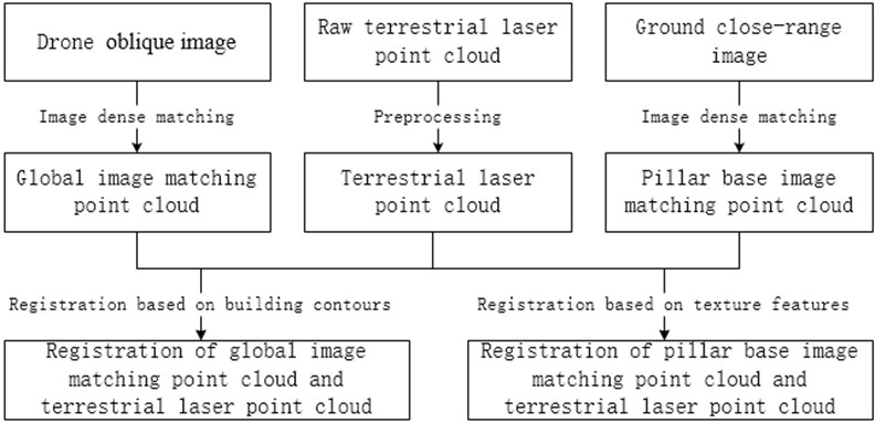
In this paper, through a comprehensive comparison and analysis of three different data characteristics of the terrestrial laser point cloud, oblique image, and ground close-range image, the following fusion process is designed and proposed, as shown in Fig. 2.
Fig. 2Data fusion flow
3. Registration and fusion of laser point cloud and image matching point cloud
In the research on the registration of terrestrial laser point cloud and image matching point cloud based on feature primitives (two data densities are quite different), the point feature primitives existing in the terrestrial laser point cloud may not necessarily match those existing in the image matching point cloud, and sparse or dense processing often leads to a loss and omission of point cloud feature information [20]. As for the surface primitives, the stable plane point clouds in the cross-source point cloud cover mostly the façade and the ground. They can hardly satisfy the requirement to create complete wall façade due to the availability of an overlapping area of cross-source point clouds. While the ground point cloud features are scarce, so it is difficult to use them as registration primitives alone [21]. As for the fusion perspective of multiple primitives, on the one hand, different sources of point cloud data induce differences in understanding the semantic information contained in the same target, on the other hand, the fusion and extraction of multiple features often complicate the algorithm [3]. At the same time, conventional buildings have regular structures and remarkable features. There is a lot of reliable information on buildings that meet the requirements of specificity and stability, such as building walls, roofs, appendages, and other contour features.
3.1. Image matching point cloud generation
After the close-range images are obtained by ground close-range photogrammetry, the 2D image data is used to generate a dense 3D point cloud with color information [22]-[23]. Firstly, the high-efficiency feature algorithm (Scale-Invariant Feature Transform, SIFT) is used to extract and match feature points on the acquired image information. Secondly, in order to improve the accuracy and stability of feature matching points, the outlier and mismatched points are eliminated by the random sampling consensus (RANSAC iterative algorithm) [24], i.e. by the 8-point method. And then to estimate the camera pose and restore the scene geometry and other information based on the Structure from Motion (SfM) algorithm [25], the BA algorithm [26] is applied for nonlinearity least squares. It optimizes camera parameters and 3D points to reduce or eliminate error accumulation and improve the robustness of the solution, and, finally, to determine the 3D space points for obtaining dense 3D point clouds. The overall cost function of the BA algorithm is as follows:
In the above formula, is the projection error, is the Lie group corresponding to the camera pose, is the sum of feature point coordinates, is the number of trajectories, is the number of viewing angles, is 1 when the camera observes the trajectory , and 0 when no trajectory is observed. is the data generated by observing the feature point at the camera pose . is the observed model, and is the observed error.
SfM algorithm is a batch method of state estimation, also known as sparse reconstruction, which uniformly processes the data observed for a period of time, and uses the observation data multiple times to estimate the camera pose and feature point coordinates at multiple times. At present, there are many kinds of open source or commercial software based on the SfM algorithm, such as ContextCapture, Pix4D, MicMac, Agisoft Metashape, etc. The specific workflow is as follows:
(1) Import images. Before importing close-range photography data, it is required to check the quality of the photos to avoid problems such as exposure, distortion, and blur that affect the accuracy.
(2) Align the photo. After importing the images, it is required to align the photos by obtaining the feature points and performing feature matching, as well as restoring the pose of the camera to obtain sparse point cloud data. The higher the selection accuracy is, the longer the corresponding processing time will be.
(3) Generate a dense point cloud. The dense point cloud data is generated through the multi-view stereo matching algorithm and by determining the optimal camera pose. At the same time, the mesh can be generated according to the generated dense point cloud data, and textures can be added to obtain a 3D model.
(4) Export the data. After data processing, the generated dense point cloud data can be exported in txt, ply, las, and other supporting formats.
3.2. Terrestrial laser point cloud and close-range image matching point cloud registration based on texture features
Because the fine components of ancient buildings have clear and rich texture features, it is relatively easy to select feature point pairs. For the registration of laser point cloud and close-range image matching point cloud, a variety of current open-source software offer the possibility of implementation, such as CloudCompare [27], a 3D point cloud processing software based on the General Public License (GPL) open-source protocol. The main principle of alignment is to determine the target and source point clouds, select at least three pairs of feature points in the corresponding point clouds with typical texture features for coarse alignment, obtain the initial transformation parameters of the two 3D point sets, and apply the Iterative Closest Point (ICP) algorithm [28] to solve the optimal transformation matrix for further optimization to achieve fine registration.
The registration based on point-line feature primitives is mainly intended to calculate the transformation of different point cloud space coordinate systems. The movement between the two coordinate systems consists of a rotation and a translation. This movement is called rigid body transformation. The laser point cloud data is used as the target point cloud , and the dense point cloud is generated based on close-range images as the source point cloud . The rigid body change of the source point cloud is as follows:
In the above formula, the relationship between the coordinate transformations of the source point cloud is described by the rotation matrix and the translation vector , so that the new source point cloud obtained from the source point cloud through transformation is the closest to the target point cloud , that is, the number of maximized points which the nearest distance between the two point sets is less than , this criterion is called Largest Common Points (LCP) [29].
The LCP transforms the point cloud registration for computing the optimal rotation and translation with minimization, so that the following formulas are satisfied:
In the above formula, and denote the corresponding point pairs in the source and target point clouds, is the number of corresponding point pairs, is the weight of the corresponding point pairs, and its specific solution process is as follows:
(1) Find the point pairs , from the target point cloud and the source point cloud.
(2) Compute the weighted centroids of both point sets:
(3) Decentralize the point pairs , found in the target point cloud and the source point cloud:
(4) Compute the 3 × 3 covariance matrix:
(5) Compute the Singular Value Decomposition (SVD) [30]:
Among them, both and are orthogonal matrices, , , , are three singular values of covariance matrix.
(6) Finally, the intended rotation is:
(7) Compute the optimal translation as:
3.3. Terrestrial laser point cloud and oblique image matching point cloud registration based on outline features
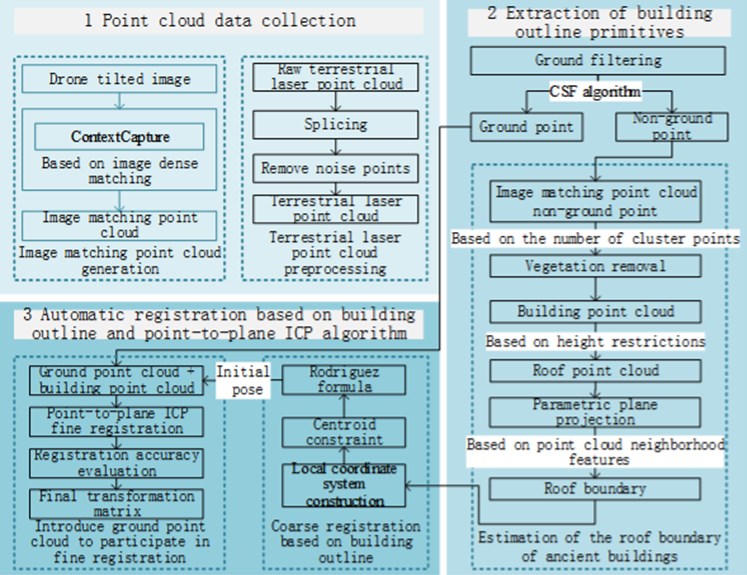
For the registration of terrestrial laser point cloud and oblique image matching point cloud, based on the paper [31], where the registration is realized within the building roof contour as the line feature constraint, and this paper improves the roof contour boundary estimation algorithm and introduces the point-to-plane ICP algorithm [32]. This is a new strategy for removing mismatched points to improve the registration efficiency and accuracy. After obtaining the data support of the oblique image matching point cloud and the terrestrial laser point cloud, the main registration technology route is shown in Fig. 3.
Fig. 3Technical route of terrestrial laser scanning point cloud and global image matching point cloud registration
3.3.1. Building outline primitive extraction
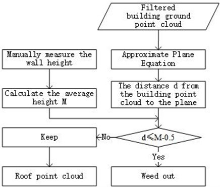
Based on the clear oblique images collected by the UAV, the dense point cloud is obtained by completing the image dense matching. After preprocessing with several steps like stitching, denoising, etc. for the original image matching point cloud, the Cloth Simulation Filter (CSF) algorithm [33] is applied to separate ground points and non-ground points. The Conditional Euclidean Clustering [34] algorithm in the Point Cloud Library (PCL) is used to remove vegetation point clouds in non-ground points based on the number of point cloud clusters. After obtaining the point cloud of the main building, the conventional roof point cloud segmentation method is achieved by removing the wall point cloud, but when the image matching point cloud building façade is missing or severely deformed, this method is not applicable. The statistical characteristics of the roof location usually show that the point cloud value is larger than other locations, so the point cloud segmentation of the ancient building roof can be achieved by setting the height limit. Initially, the least square fitting algorithm [35] is used to compute the plane equation of the location of the building ground point cloud. After that, the height from the roof to the ground is manually measured several times, and the relationship between the mean height and the distance is calculated and compared from the point to the plane equation, and then the roof segmentation is completed. Since the approximate plane is not completely close to the ground, the average height is reduced by 0.5 meters and compared with d. The specific process is shown in Fig. 4.
Fig. 4Process of segmentation of roof point cloud
After the parametric plane projection of the obtained roof point cloud, a boundary estimation algorithm based on point cloud neighborhood features can be used to obtain the outer boundary roof point cloud. The algorithm takes the above-mentioned 2D roof plane point cloud as the input, and then the algorithm is processed, the 2D roof boundary is obtained. Combined with Fig. 5, the specific algorithm principle and process description of the algorithm are as follows:
Fig. 5Roof boundary estimation algorithm based on point cloud neighborhood features
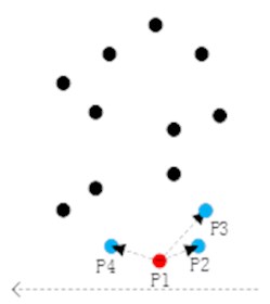
a) Point with minimum Y
b) Next boundary point
c) Traversal check
(1) Remove the duplicate points in the point cloud of the 2D roof plane, establish a tree for the point cloud after deduplication, and traverse the point with the smallest value in the search point set. Take the point P1 in the above figure as an example, where the value of point P1 is , and P1 is the starting point (red point) and current point of boundary estimation (Fig. 5(a)).
(2) After finding the current point, perform a neighborhood search for the current point, and search for the nearest points. When 3, the nearest neighbor points are P2, P3, and P4. These three nearest neighbor points are used as candidate points for the next boundary point search, and the current point is connected with all candidate points. If the left direction of the -axis is taken as the positive direction of the coordinate axis, point P2 is the point with the largest direction angle in the positive direction among all the points connected to P1 (Fig. 5(b)). At this point, point P2 is set as the next starting point and current point for boundary estimation.
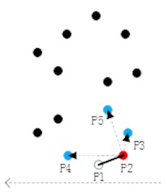
(3) Connect the two boundary points P1 and P2 with a line (black solid line), perform a neighborhood search for a new current point, and search for the nearest points. When 3, the nearest neighbor points are P3, P4, and P5, and the three nearest neighbor points are used as candidate points for the next boundary point search. They all are connected with the current point to find the point where the connecting line and the previous boundary line of segment P1-P2 form the largest direction angle, which is set as the next starting point and current point for the boundary estimation.
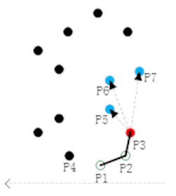
(4) Iterative step (3) and traverse are applied to check all points until returning to the starting point P1, where the boundary estimation ends, and all boundary points are obtained (Fig. 5(c)).
3.3.2. Coarse registration based on building contours
In the outline point cloud for a building roof, the transformation matrix is obtained to complete the coarse registration through the centroid constraint and Principal Component Analysis (PCA) [36]. Firstly, for the extracted image matching point cloud building contours and terrestrial laser point cloud building contours, the center-of-mass constraints are established to find the center-of-mass difference, and the translation parameters are determined in the coarse registration transformation matrix . The usual formula for calculating the center-of-mass coordinates of an object is as follows:
Among them, , are the coordinates of each mass point, is the mass corresponding to the mass point. To calculate the point cloud center of mass, let the above equation , and the formula for calculating the center-of-mass coordinates of the point cloud can be rewritten as Eq. (11):
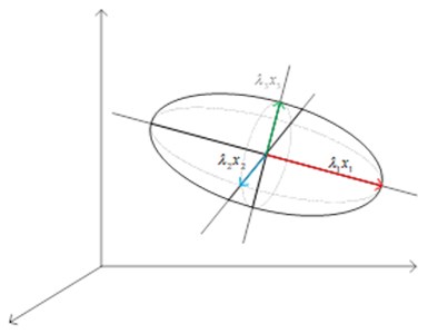
According to the above equation, the center-of-mass coordinates of the source and target point clouds are calculated separately, and the translation matrix required for coarse registration can be determined by finding the difference in the center-of-mass coordinates. Then the PCA algorithm is used to downscale the building contour point cloud and construct the local coordinate system. As shown in Fig. 6.
(1) For the nearest neighbor of a point in the point cloud , the corresponding covariance matrix can be calculated by Eq. (12):
where, is the number of neighboring points, is the center of mass of the point cloud found in the previous section.
(2) According to Eq. (13), the three largest eigenvalues , , and the eigenvectors , , are obtained:
(3) The eigenvectors corresponding to the three eigenvalues are orthogonal to each other, and the eigenvector is in the same direction as the normal vector of a plane of the point cloud , and the plane formed by the eigenvectors and is orthogonal to the eigenvector , the three eigenvectors , , corresponding to these three eigenvalues can ideally characterize the three axes , , in the local coordinate system of the point cloud to achieve the purpose of data dimensionality reduction and local coordinate system construction. And finally, the vectors of the source and target point clouds representing the corresponding coordinate axes into the Rodriguez formula [37] are substituted to calculate the rotation matrix.
Fig. 6Representation of principal component by PCA algorithm
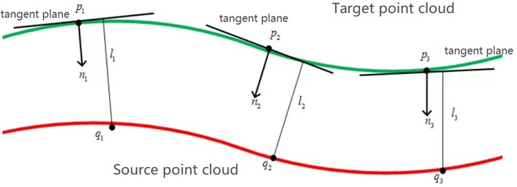
3.3.3. Point-to-plane ICP algorithm for fine registration
After the coarse registration, the previous method directly uses the ICP algorithm to achieve the fine registration, because of the differences ignored in the density and acquisition perspective of the two cross-source point clouds [38]-[40], it often leads to a local optimum in registration, and the use of point-to-plane ICP algorithm [32] can improve this problem. By changing the original rule of the minimum distance between points, the minimum distance from the point to the tangent plane of the corresponding point is used as the object of iterative optimization. The core diagram of the algorithm is shown in Fig. 7. Due to the influence of gimbal jitter, camera shooting angle, and error of dense matching algorithm in the image data acquisition stage, the point cloud of image matching generated has a horizontal point accuracy that is 1/3 higher than the vertical point accuracy [41]. Therefore, the ground point cloud separated in the ground filtering and the main point cloud of the building are introduced to ensure the fine registration. First, the main point cloud of the building is restored to the ground point cloud, and then the coarse registration transformation matrix is used to transform the fused point cloud. After making the two cross-source point clouds in a roughly aligned state, the point-to-plane ICP algorithm is used to complete the fine registration.
In Fig. 7, the red line indicates the source point cloud, the green line indicates the target point cloud, is the point on the target point cloud, is the point on the source point cloud, indicates the tangent plane distance from the point on the source point cloud to the corresponding point on the target point cloud. For the point-to-plane ICP algorithm, the error function is designed by minimizing the sum of squared point-to-plane distances as in Eq. (14):
where, is the normal vector of the point , and is the (4×4) transformation matrix consisting of the rotation matrix and translation matrix .
The above registration methods solve the problems of different geometric reference frames, inconsistent scales, and inconsistent density of point clouds, so that the registered data has high-precision three-dimensional coordinate information, diverse perspective and scale features, and rich spectral information.
Fig. 7Diagram of point-to-plane ICP algorithm
4. Experiments
4.1. Data collection and preprocessing
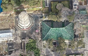
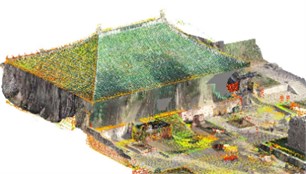
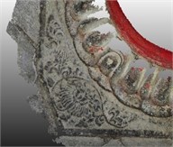
In this paper, the data about ancient building restoration were collected. These data mainly concern a temple, which was taken as the core survey object, and has the total construction area of 658.29 square meters. In order to understand fully the surrounding environment of the scenic spot and the current preservation status of the temple’s roof, firstly, the whole-range oblique images of the scenic spot were obtained through aerial photography by UAV (Fig. 8(a)); then, the high-overlapped clear ground close-range photos of the temple pillar base were captured by a digital camera (Fig. 8(b)); Finally, the indoor and outdoor building structures of the temple were scanned by a terrestrial laser scanner to obtain a high-precision terrestrial laser point cloud (Fig. 8(c)).
Fig. 8Raw data
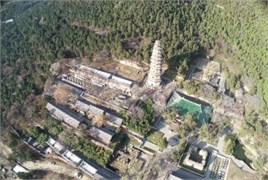
a) UAV oblique photography image
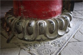
b) Close-range photography image
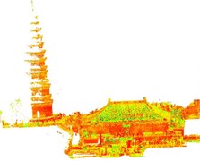
c) Terrestrial laser point cloud
DJI Phantom 4 RTK has been applied as the oblique image data acquisition device in this paper. It integrates a new RTK module with real-time positioning accuracy up to the centimeter level, with more stable anti-magnetic interference function and accurate positioning ability. These functions improve the absolute accuracy of image data. The basic parameters of UAV equipment parameters and image matching point cloud data are shown in Table 2.
Table 2Detailed table of UAV oblique images
Instrument model | Camera model | Sensor size | Heading and sideways overlap | Number of photos | Image matching method | Image matching point number |
DJI phantom 4RTK | FC6310R | 13.2 mm×8.8 mm | 80 % | 167 | Context capture | 99235744 |
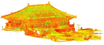
In case of using the ContextCapture, there are some steps to generate the dense image matching point cloud from UAV oblique images, such as aerial triangulation, calculation of external orientation elements, generation of sparse and dense point clouds, and so on, as shown in the following Fig. 9(a).
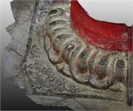
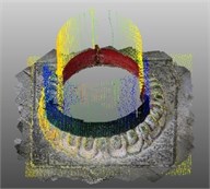
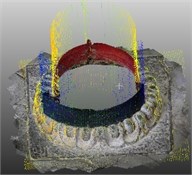
Fig. 9Three kinds of cross-source point clouds
a) Oblique image matching point cloud
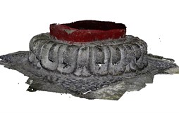
b) Pillar base close-range image matching point cloud

c) Pillar base 3D laser point cloud
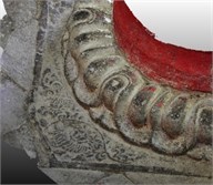
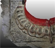
Canon EOS 70D has been applied as the close-range image data acquisition device in this paper. There are two main methods of shooting close-range images: upright photography and cross-direction photography [42]. The objects of the ground close-range image are mainly the pillar bases in the temple, which are small, but the surface of each pillar base is engraved with different carvings, and the texture is complex and exquisite, so the cross-direction photography is taken. After filtering and preprocessing raw images, the authors use Agisoft Metashape to generate the dense point cloud of the pillar base in the temple according to the ground close-range images, as shown in Fig. 9(b) above. The basic information about the camera for ground close-range photogrammetry for the pillar bases is presented in Table 3.
Table 3Detailed table of close-range images
Instrument model | Number of photos | Photography method | Degree of overlap | Maximum convergence angle | Shooting distance | Image matching method |
Canon EOS 70D | 40 | Cross direction photography | 80 % | 15° | 0.4m | Agisoft Metashape |
Faro Focus 3D X130 has been applied as the terrestrial laser point cloud data (Fig. 9(c)) acquisition equipment. When scanning a certain volume of buildings, it is necessary to set up stations for multiple scans. After scanning the terrestrial laser point cloud, the point cloud stitching of multiple stations is completed first. Then the noise points and outlier points (such as walking tourists, distant vegetation, etc.) contained in the point cloud shall be processed manually and with Statistical Outlier Removal (SOR) algorithm to complete the filtering operation. The basic information for terrestrial laser point cloud data acquisition and pre-processing operations is shown in Table 4, where the SOR parameter is the number of points to use for mean distance estimation, is the standard deviation multiplier threshold.
Table 4Detailed table of terrestrial laser point clouds
Instrument model | Number of stations | Raw point number | Number of points after manual processing | SOR parameter ( | Points after SOR filtering | Proportion of remaining points |
Faro Focus 3D X130 | 74 | 97655229 | 42263526 | 10/2.0 | 42194589 | 99.84 % |
4.2. Data fusion
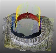
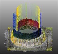
The dense point cloud data of the pillar base in the temple are obtained from a close-range image with higher texture details. Then it is matched with the terrestrial laser point cloud using the registration method based on the above-mentioned point-line texture primitives. The experiment adopts Align and ICP methods in CloudCompare with the following steps: 1) load the laser point cloud and the close-range image matching point cloud, 2) select at least three pairs of feature points in the target point cloud and the source point cloud, and 3) perform two types of point clouds coarse and fine registration. Thereby the registered point cloud is intended to supplement the lack of detailed texture of the terrestrial laser point cloud (Fig. 10).
Fig. 10Visualization effect of registration of close-range image matching point cloud and terrestrial laser scanning point cloud
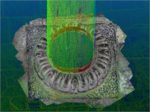
Fig. 11Roof boundary and local coordinate system of point cloud
a) Oblique image matching point cloud roof boundary
b) Terrestrial laser point cloud roof boundary
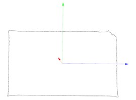
c) Oblique image matching point cloud roof boundary local coordinate system
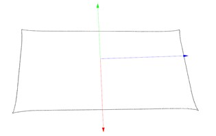
d) Terrestrial laser point cloud roof boundary local coordinate system
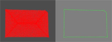
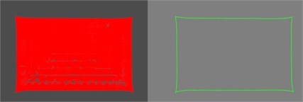
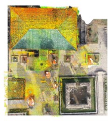
As for the fusion of the oblique image matching point cloud and the terrestrial laser point cloud, after ground and vegetation filtering, the building contour primitive extraction and registration of the two cross-source point clouds are completed according to the above-mentioned technical process. Firstly, based on the respective roof contour boundaries, the covariance matrix, eigenvalues, and corresponding eigenvectors of the two point clouds are calculated separately according to the PCA algorithm, which in turn determines the respective local coordinate systems of the two point clouds (Fig. 11).
Secondly, the difference in the center of mass of the two point clouds is calculated to determine the translation parameters. Then the vectors representing the coordinate axes into the Rodriguez formula [37] are substituted to calculate the rotation matrix and complete the roof boundary coarse registration, as shown in Fig. 12. In this Figure, the blue line indicates the image matching point cloud after rotation and translation, the red one indicates the terrestrial laser point cloud, and the two contour point clouds are roughly aligned after registration to provide a good initial position for fine registration.
Fig. 12Roof boundary coarse registration
Before the fine registration, the following steps are provided: 1) restore the main point cloud of the building to the ground point (see Fig. 13), 2) transform the fused point cloud by the coarse registration transformation matrix, so that the two cross-source point clouds are roughly aligned. The visualization effect of fine registration by the point-to-plane ICP algorithm after 500 iterations of computation is shown in Fig. 14, and the final transformation matrix is shown in Eq. (15):
Fig. 13Point cloud for fine registration of point-to-plane ICP algorithm
a) Image matching point cloud after introducing ground point cloud
b) Terrestrial laser point cloud after introducing ground point cloud
4.3. Accuracy analysis
4.3.1. Accuracy analysis for close-range image matching point cloud and terrestrial laser point cloud
In order to explore the influence of different parameter settings on the point clouds accuracy and calculation results during the use of commercial software, the parameters are set according to the four levels of highest, high, medium, and low respectively when the ground close-range images facing the inner pillar bases of the temple generate a dense point cloud. The low point cloud model results are used as the benchmark for comparison. For 48 close-range images of a certain pillar base, the differences among the photo alignment time, dense point cloud generation time, total time, and Root Mean Square (RMS) re-projection error involved in different parameter settings are shown in Table 5.
Fig. 14Result of fine registration
a) Top view
b) Side view
c) Local view
Table 5Accuracy of column base point cloud model under different parameters
Parameter settings | Photo alignment time / min | Dense point cloud generation time / min | Total time / min | RMS / pixel | Image matching point cloud number |
Highest | 3.4 | 12.9 | 16.3 | 0.0981 | 254444765 |
High | 2.3 | 5.96 | 8.26 | 0.1527 | 54300196 |
Medium | 1.2 | 2.7 | 3.9 | 0.4503 | 12340414 |
Low | 0.5 | 1.1 | 1.6 | 0.8724 | 2954183 |
As described in Table 5, when the model parameters are increased by one level, the photo alignment time and the dense point cloud generation time almost double, but the RMS re-projection error of the result point cloud continues to shrink, and the point cloud model accuracy continues to be improved. A comparison of the accuracy of a pillar base local model with four parameter settings and the registration are respectively shown in Fig. 15. Because the inner pillar base of the temple occupies a small area and is rich in texture details, the number of close-range photos that need to be taken is less than the number of oblique images. Therefore, when dense point clouds are generated under the hardware equipment conditions allowed, highest model parameter settings can be used to ensure the accuracy of their detailed texture features.
Aiming at the analysis of the registration accuracy between the close-range image matching point cloud and the terrestrial laser point cloud, the Align and ICP methods are used in CloudCompare to complete the registration. The root mean square error (RMSE) of the Euclidean distance between the nearest neighbors of the source and target point clouds is chosen as the evaluation index of the registration accuracy. This index is calculated according to Eq. (16-17), in which the best RMSE of the dense point cloud with highest parameter settings and the laser point cloud is 0.216495 cm after fine registration:
where is total number of all corresponding points after registration, is the Euclidean distance between the th nearest neighbor point in the target point cloud and the corresponding point in the aligned source point cloud , smaller value indicates higher accuracy of automatic registration.
Fig. 15Comparison of accuracy and registration of different parameter pillar base dense point cloud models (above: corresponding local models, below: registration of image matching point cloud and laser point cloud)
a) Highest
b) High
c) Medium
d) Low
4.3.2. Accuracy analysis for oblique image matching point cloud and terrestrial laser point cloud
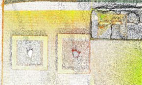
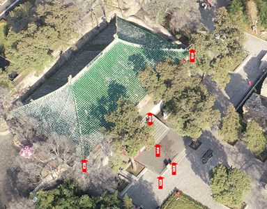
For an analysis of the registration accuracy between the oblique image matching point cloud and the terrestrial laser point cloud, a total of 6 points on the building and ground are selected, as shown in Fig. 16. The different ratios are set to remove the mismatched points after fine registration. Compared with 0 % (no removal), when the removal ratio of the mismatched points is set to 15 %, the registration error is the smallest (Table 6). Meanwhile, the registration accuracy of the ground point cloud at all three locations is higher than that of the building point cloud, which is closely related to the horizontal and vertical point accuracy of image matching point clouds and the principle of point-to-plane ICP algorithm. The average value of the optimal registration error at the three ground locations (Table 6) is 2.1964 cm. Finally, the average improvement in registration accuracy after removing the mismatched points according to the optimal ratio is 20.2 % (Table 7).
Table 6Registration error after removing mismatched points in different proportions (cm)
Proportional threshold (%) | Ground | Building | ||||
Position 1 | Position 2 | Position 3 | Position 4 | Position 5 | Position 6 | |
0 | 2.7769 | 2.7221 | 2.8521 | 6.3723 | 6.3508 | 4.6493 |
10 | 2.4971 | 2.5545 | 2.6502 | 6.2573 | 6.2453 | 4.5967 |
15 | 2.2088 | 2.2238 | 2.1567 | 6.1218 | 6.1906 | 4.0558 |
20 | 2.3145 | 2.3061 | 2.4844 | 6.1869 | 6.2130 | 4.3718 |
Table 7Mismatched point removal ratio and accuracy improvement
Dataset | Mismatched point removal optimal ratio | Average improvement in accuracy after removal of mismatched points |
Temple | 15 % | 20.2 % |
Fig. 16Temple location markers
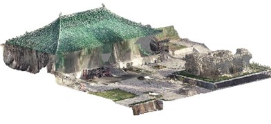
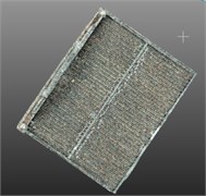
In order to verify the feasibility of the method mentioned in subsection 3.3 of this paper, we added Guangzhou ancient building data with fewer ground points for roof contour feature extraction and registration accuracy analysis, as shown in Fig. 17. Then we compared the results of two datasets with the manual registration in CloudCompare (Table 8). The RMSEs obtained in CloudCompare are respectively 3.6438 cm and 12.6334 cm, while the RMSEs obtained by using the registration method from this paper to remove the mismatched points are respectively 2.2016 cm and 10.0381 cm. In comparison with CloudCompare, the accuracy of registration of the two datasets based on our method is improved.
Fig. 17Visualization of school dataset results
a) Terrestrial laser point cloud of building
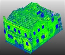
b) Oblique image matching point cloud of building
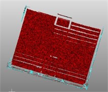
c) Terrestrial laser point cloud roof
d) Oblique image matching point cloud roof
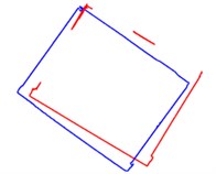
e) Roof boundary coarse registration
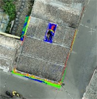
f) Top view of fine registration
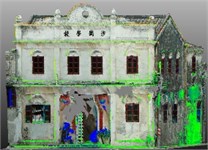
g) Side view of fine registration
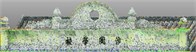
h) Local view of fine registration
Table 8Comparison of registration accuracy (RMSE)
Dataset | Cloud compare (cm) | Method of this paper (cm) | Accuracy improvement (%) |
Temple | 3.6438 | 2.2016 | 39.6 |
School | 12.6334 | 10.0381 | 20.5 |
4.4. Discussion
The experiments show that the proposed method is effective, but there are still several aspects to discuss:
– Data collection.
Because the buildings in temple dataset are located in mountainous areas and there are many occlusions (for example: tall trees) around them, the shape of the point clouds at the above-occluded positions does not match the actual shape of the buildings based on the image matching point cloud generated by the existing oblique images. These missing situations are also actual for high-rise buildings, such as the school mentioned above. Therefore, with due course of data accumulation, it will be possible to consider the involvement of drones to low-altitude flights for supplementary shots at such locations. Then supplementary shots are added to oblique images to participate in intensive image matching. Thus, the method works can be verified by additional experiments.
– Data processing.
1. Feature primitive extraction: The building outline features in this paper mainly include the roofs of ancient buildings in the coarse registration stage. Although they can be used as feature primitives to achieve the coarse registration for the considered data sets, but many different styles of buildings may be used in the same dataset. At present, this paper has not carried out research on the method of registration based on other feature primitives, and the rigor of the classification and extraction of feature primitives needs to be improved.
2. Point cloud filtering: In the face of redundant point clouds that cannot be removed by ground and vegetation filtering, such as flower beds, independent appendages outside buildings, and bulky vegetation, it is still necessary to select and delete them manually. This reduces the degree of the method automation to a certain extent. In the future, it will be required to consider introducing a more refined point cloud segmentation algorithm to improve the automation of the registration method used in this paper.
3. Data processing volume: Before the extraction of feature primitives and point cloud filtering, in order to improve computing efficiency, point cloud sparse operation is often performed on the point cloud dataset to be processed. Therefore, while some point clouds are deleted, to a certain extent, some characteristics of the point clouds eliminated in the thinning process are inevitably ignored. Of course, this is also the problem to be solved for most of the current point cloud data processing methods. The common solution of the existing methods is as follows: improving computer hardware performance.
– Data fusion.
Regarding the registration accuracy of the registration method used in this paper, it depends to a certain extent on the robustness of the point-to-plane ICP algorithm. When looking for the tangent plane corresponding to the nearest point, if the point cloud is too sparse, it may lead to an increase of mismatched point pairs. The specific relationship between cross-source point cloud density difference and registration accuracy can be studied in the follow-up, and the precise registration algorithm can be improved.
5. Conclusions
This paper mainly takes a temple in a scenic spot in the Shandong Province as an example, combines terrestrial laser scanning, UAV oblique photography, and close-range photography to collect multi-source and multi-scale 3D data of the ancient building. Moreover, it realizes the fusion of multi-source and multi-scale 3D data of the air-ground integration through the registration of the close-range photography point cloud, oblique photography point cloud and terrestrial laser point cloud according to the building roof profile and point-line features. Considering the situation that the building roof point cloud of the terrestrial laser point cloud is missing, and the image matching point cloud of building façade is missing or unrealistic, the authors created a point cloud model as per this paper method. It overcomes to a certain degree the point cloud hole of a single type of point cloud, and makes the building façade and roof information complete. At the same time, the image matching point cloud assigns its own RGB information to the laser point cloud, and the color point cloud formed by the two point sets enriches the attributes of the point cloud model. The collection and fusion of multi-source data can improve the accuracy and speed of point cloud acquisition of ancient buildings, and provide the basic point cloud data for post-production of three-dimensional models of ancient buildings, drawing plans, etc., so as to improve the digitization of ancient buildings and the protection of historical buildings.
Based on the existing research results, in order to improve the registration accuracy and efficiency of the method applied in this paper, the perspective study will consider: 1. Dense matching of multi-angle oblique images. Specifically explore whether images from manual low-altitude aerial photography, which are jointly involved in the dense matching process of aerial imagery, can complete the match and increase the number of point clouds in the obscured area. 2. Selection and comparison of feature primitives. From the perspective of surface primitives or multi-primitive fusion, mining various types of potential registration primitives, such as doors, balconies, etc., can be considered so that the registration method can be applied to scenes that are more complex. 3. Registration accuracy. The precise registration of the method used in this paper needs to be carried out under the condition of containing a large area of the plane point cloud (for example: ground point cloud), and the datasets containing a large range of low-rise buildings can be introduced to verify the method feasibility in future.
References
-
B. S. Yang, F. X. Liang, and R. G. Huang, “Research progress, challenges and trends of 3D laser scanning point cloud data processing,” (in Chinese), Journal of Surveying and Mapping, Vol. 46, No. 10, pp. 1509–1516, 2017, https://doi.org/10.11947/j.agcs.2017.20170351
-
A. Safdarinezhad, M. Mokhtarzade, and M. J. Valadan Zoej, “An automatic method for precise 3D registration of high resolution satellite images and airborne LiDAR data,” International Journal of Remote Sensing, Vol. 40, No. 24, pp. 9460–9483, Dec. 2019, https://doi.org/10.1080/01431161.2019.1633698
-
Q. Zhu et al., “A review of multi-point cloud data fusion methods for 3D city modeling,” (in Chinese), Journal of Wuhan University (Information Science Edition), Vol. 43, No. 12, pp. 1962–1971, 2018, https://doi.org/10.13203/j.whugis20180109
-
X. X. Yuan et al., “Research progress and prospect of dense matching of aerial images,” (in Chinese), Journal of Surveying and Mapping, Vol. 22, No. 2, pp. 555–568, 2019, https://doi.org/10.11947/j.agcs.2019.20190453
-
A. Mahphood, H. Arefi, A. Hosseininaveh, and A. A. Naeini, “Dense multi-view image matching for dsm generation from satellite images,” in The International Archives of the Photogrammetry, Remote Sensing and Spatial Information Sciences, Vol. XLII-4/W18, pp. 709–715, Oct. 2019, https://doi.org/10.5194/isprs-archives-xlii-4-w18-709-2019
-
J. Zhang and W. S. Jiang, “Laser point cloud and optical image registration: current situation and trend,” (in Chinese), Journal of Earth Information Science, Vol. 19, No. 4, pp. 528–539, 2017, https://doi.org/10.3724/sp.j.1047.2017.00528
-
B. Yang and J. Wang, “Mobile mapping with ubiquitous point clouds,” Geo-spatial Information Science, Vol. 19, No. 3, pp. 169–170, Jul. 2016, https://doi.org/10.1080/10095020.2016.1244982
-
X. Huang, G. Mei, J. Zhang, and R. Abbas, “A comprehensive survey on point cloud registration,” arXiv:2103.02690, 2021, https://doi.org/10.48550/arxiv.2103.02690
-
K. Chen et al., “Application of 3D modeling method integrating UAV and camera images in ancient building protection,” (in Chinese), Science and Technology Innovation and Application, Vol. 26, pp. 30–32, 2020.
-
B. Y. Sun et al., “Application of 3D reconstruction technology combining aerial photography and ground photos in archaeology,” (in Chinese), Science Technology and Engineering, Vol. 19, No. 17, pp. 262–266, 2019, https://doi.org/10.3969/j.issn.1671-1815.2019.17.039
-
R. L. Shi, “Research on the application of BIM technology, 3D scanning technology and GIS technology in the restoration and protection of ancient buildings,” (in Chinese), Software, Vol. 41, No. 9, pp. 123–126, 2020, https://doi.org/10.3969/j.issn.1003-6970.2020.09.034
-
L. Song, “Application of new technologies in the protection of ancient buildings,” (in Chinese), Urban Architecture, Vol. 17, No. 21, pp. 136–137, 2020, https://doi.org/10.3969/j.issn.1673-0232.2020.21.054
-
H. X. Yin and J. H. Yang, “Application of multi-source heterogeneous point cloud fusion technology in the preservation of ancient building information,” (in Chinese), Bulletin of Surveying and Mapping, Vol. 9, pp. 162–164, 2020, https://doi.org/10.13474/j.cnki.11-2246.2020.0307
-
Q. N. Meng, H. D. Zhang, M. L. Men, Y. X. Hu, and X. L. Sun, “Application of aerial oblique photography and 3D laser scanning technology in the restoration of ancient buildings,” (in Chinese), Urban Survey, 2021, https://doi.org/10.3969/j.issn.1672-8262.2021.05.025
-
B. Y. Sun, X. Zhou, Y. C. Qin, L. H. Wei, and G. H. Ge, “Application of multi-data mutual auxiliary fusion technology of open space in reconstruction of large-scale ancient buildings,” (in Chinese), Bulletin of Surveying and Mapping, 2022.
-
C. Lu, “Algorithm of 3D virtual reconstruction of ancient buildings in Qing dynasty based on image sequence,” Security and Communication Networks, Vol. 2021, pp. 1–10, Dec. 2021, https://doi.org/10.1155/2021/8388480
-
H. Bagheri, M. Schmitt, and X. Zhu, “Fusion of multi-sensor-derived heights and OSM-derived building footprints for urban 3D reconstruction,” ISPRS International Journal of Geo-Information, Vol. 8, No. 4, p. 193, Apr. 2019, https://doi.org/10.3390/ijgi8040193
-
P. Rodríguez-Gonzálvez et al., “4D reconstruction and visualization of cultural heritage: analyzing our legacy through time,” The International Archives of the Photogrammetry, Remote Sensing and Spatial Information Sciences, Vol. 42, pp. 609–616, Feb. 2017, https://doi.org/10.5194/isprs-archives-xlii-2-w3-609-2017
-
A. Klimkowska, S. Cavazzi, R. Leach, and S. Grebby, “Detailed three-dimensional building façade reconstruction: a review on applications, data and technologies,” Remote Sensing, Vol. 14, No. 11, p. 2579, May 2022, https://doi.org/10.3390/rs14112579
-
B. Yang, Y. Zang, Z. Dong, and R. Huang, “An automated method to register airborne and terrestrial laser scanning point clouds,” ISPRS Journal of Photogrammetry and Remote Sensing, Vol. 109, pp. 62–76, Nov. 2015, https://doi.org/10.1016/j.isprsjprs.2015.08.006
-
Y. Zang, B. Yang, J. Li, and H. Guan, “An accurate TLS and UAV image point clouds registration method for deformation detection of chaotic hillside areas,” Remote Sensing, Vol. 11, No. 6, p. 647, Mar. 2019, https://doi.org/10.3390/rs11060647
-
Y. S. Li, “Research on key technologies of fast stereo matching of photogrammetric images,” (in Chinese), Wuhan, China: Wuhan University, 2018.
-
D. Yang, S. F. Wei, and J. Wang, “An image-based point cloud generation method for ancient buildings,” (in Chinese), Science of Surveying and Mapping, Vol. 46, No. 1, pp. 130–135, 2021, https://doi.org/10.16251/j.cnki.1009-2307.2021.01.017
-
R. Schnabel, R. Wahl, and R. Klein, “Efficient RANSAC for point-cloud shape detection,” Computer Graphics Forum, Vol. 26, No. 2, pp. 214–226, Jun. 2007, https://doi.org/10.1111/j.1467-8659.2007.01016.x
-
J. L. Schonberger and J.-M. Frahm, “Structure-from-motion revisited,” in 2016 IEEE Conference on Computer Vision and Pattern Recognition (CVPR), pp. 4104–4113, Jun. 2016, https://doi.org/10.1109/cvpr.2016.445
-
E.-K. Stathopoulou and F. Remondino, “Multi-view stereo with semantic priors,” The International Archives of the Photogrammetry, Remote Sensing and Spatial Information Sciences, Vol. XLII-2/W15, pp. 1135–1140, Aug. 2019, https://doi.org/10.5194/isprs-archives-xlii-2-w15-1135-2019
-
“CloudCompare 2020 Developers course, http://www.cloudcompare.org.”.
-
S. Rusinkiewicz and M. Levoy, “Efficient variants of the ICP algorithm,” in Proceedings Third International Conference on 3-D Digital Imaging and Modeling, 2001, https://doi.org/10.1109/im.2001.924423
-
J. Yon, S.-W. Cheng, O. Cheong, and A. Vigneron, “Finding largest common point sets,” International Journal of Computational Geometry and Applications, Vol. 27, No. 3, pp. 177–185, Sep. 2017, https://doi.org/10.1142/s0218195917500029
-
O. Sorkine-Hornung and M. Rabinovich, Least-squares rigid motion using SVD. Technical Notes, 2009.
-
S. F. Wei et al., “Research on the registration of terrestrial laser point cloud and image matching point cloud based on building outline,” (in Chinese), Computer Application Research, Vol. 38, No. 8, 2021, https://doi.org/10.19734/j.issn.1001-3695.2020.08.0393
-
Kok-Lim Low, “Linear least-squares optimization for point-to-plane ICP surface registration,” Chapel Hill, University of North Carolina, Vol. 4, No. 10, pp. 1–3, 2004.
-
W. Zhang et al., “An easy-to-use airborne LiDAR data filtering method based on cloth simulation,” Remote Sensing, Vol. 8, No. 6, p. 501, Jun. 2016, https://doi.org/10.3390/rs8060501
-
H. Guo, Point Cloud Library PCL from Entry to Master. (in Chinese), China: Machinery Industry Press, 2019.
-
L. Cai, K. Wu, Q. Fang, and R. Zheng, “Fast 3D modeling Chinese ancient architectures base on points cloud,” in 2010 International Conference on Computational Intelligence and Software Engineering (CiSE), pp. 1–3, Dec. 2010, https://doi.org/10.1109/cise.2010.5677165
-
N. Locantore et al., “Robust principal component analysis for functional data,” Test, Vol. 8, No. 1, pp. 1–73, Jun. 1999, https://doi.org/10.1007/bf02595862
-
L. Y. Chen, “Research on 3D coordinate conversion method based on Rodriguez matrix,” (in Chinese), Geospatial Information, Vol. 16, No. 11, p. 107, 2018, https://doi.org/10.3969/j.issn.1672-4623.2018.11.031
-
X. Huang, J. Zhang, L. Fan, Q. Wu, and C. Yuan, “A systematic approach for cross-source point cloud registration by preserving macro and micro structures,” IEEE Transactions on Image Processing, Vol. 26, No. 7, pp. 3261–3276, Jul. 2017, https://doi.org/10.1109/tip.2017.2695888
-
X. Huang, “Learning a 3D descriptor for cross-source point cloud registration from synthetic data,” arXiv:1708.08997, 2017, https://doi.org/10.48550/arxiv.1708.08997
-
S. Rhee and T. Kim, “Dense 3D point cloud generation from UAV images from image matching and global optimization,” The International Archives of the Photogrammetry, Remote Sensing and Spatial Information Sciences, Vol. XLI-B1, pp. 1005–1009, Jun. 2016, https://doi.org/10.5194/isprs-archives-xli-b1-1005-2016
-
J. Yu, L. Ma, M. Tian, and X. Lu, “Registration and fusion of UAV LiDAR system sequence images and laser point clouds,” Journal of Imaging Science and Technology, Vol. 65, No. 1, pp. 10501–1-10501-9, Jan. 2021, https://doi.org/10.2352/j.imagingsci.technol.2021.65.1.010501
-
J. Li, “Research on refined reality modeling and visualization based on air-ground fusion,” (in Chinese), Xi’an University of Science and Technology, Xi’an, China, 2018.
Cited by
About this article

