Abstract
Regenerative chatter is an unstable form of self-excited vibration in the machining process, and it is one of the main obstacles which limit the productivity and the surface quality of the component. This paper investigates the effect of 2-D vibration assistance on high frequency regenerative chatter in the micro milling process. External vibration is applied on the workpiece in a range of frequencies and amplitudes using the piezoelectric actuators. The chatter vibration is monitored using the sound pressure signal measured by the microphone. The chatter amplitude with vibration assistance in 1-D (feed or normal direction) and 2-D is studied. The effect of the frequency and amplitude of the vibration assistance on chatter amplitude is analyzed. It is concluded that the vibration assistance is able to effectively attenuate the high frequency chatter by modifying the dynamic chip thickness and adding process damping in the micro milling process.
1. Introduction
Regenerative chatter is a self-excited vibration which causes poor surface quality, inaccuracy, excessive noise and machine tool damage in the machining process. The presence of chatter vibration reduces the efficiency and overall productivity. Extensive research has been conducted to predict or suppress chatter in the machining processes. In the micro-milling operation, chatter occurs at higher frequency (above 4000 Hz) compared to conventional milling due to reduced size of the cutting tool, which generates new challenges in developing effective strategy for chatter attenuation [1].
Numerical and experimental solutions have been developed in the past to reduce chatter vibration in the machining process. The chatter suppression techniques are classified into two main categories: passive and active chatter suppressions. The passive techniques are designed to suppress chatter by using additional devices such as dampers or by improving the machine tool design [2-5]. Passive suppression technique is inexpensive and easy to implement. However, it requires very accurate tuning for desired performance which is difficult due to uncertainties in the machine-tool structure and the cutting process. Active techniques continuously monitor the dynamic state of the machine tool system, and output control signal to suppress chatter. Active chatter suppression was successfully applied in varying process parameters such as feed rates, spindle speeds [6], rake angle [7] and clearance angle [8] by monitoring the force signal. Vibration control system was developed to suppress chatter, including fuzzy logic controller [9, 10] and adaptive control [11, 12]. However, the implementation of active control is costly because the system requires more complex hardware and software. Furthermore, the chatter frequencies dealt with in the active chatter suppression in the literatures are all below 1000 Hz due to the limitation of the controller’s frequency bandwidth. In the micro milling process, chatter frequency may occur in the range of 4,000-10,000 Hz, therefore, the active control technique is unable to suppress high frequency chatter.
Vibration assisted machining (VAM) is a technique by applying external vibration at high frequency and small amplitude to create relative displacement between the cutting tool and the workpiece in addition to the original cutting motion. Lately, the effect of VAM on the chatter vibration was investigated in orthogonal turning process. Xiao et al. [13] developed an experimental system to study the precision machining mechanism of vibration cutting which can provide an effective solution to the chatter attenuation. It was shown that chatter was suppressed in ultrasonic vibration assisted machining process. Tabatabaei et al. [14] developed a theoretical model on the effect of ultrasonic vibration assistance on chatter. The regenerative chatter suppression for high chip removal was presented by considering the bending mode of the tool. Yao et al. [15] presented a chatter control system on the basis of harmonic excitation of a workpiece for orthogonal cutting. It was shown that the parametric excitation with an appropriate frequency and large amplitude can suppress chatter effectively. Ma et al. [16] proposed a theoretical model to suppress chatter by adding ultrasonic elliptical vibration on the cutting tool. The experimental investigations showed that the regenerative chatter occurring in ordinary turning operation was effectively suppressed by applying ultrasonic elliptical vibration. Overall, the findings from these studies have consistently shown the significant effect of vibration assistance on the chatter vibration. However, the methods listed above are only focused on the turning process. The effect of vibration assistance on the cutting mechanisms between turning and milling processes are substantially different: in turning process, the added vibration increases the shear angle thus reduces the cutting force; while in milling process, the vibration assistance modifies the dynamic chip thickness by changing the relative tool-workpiece trajectory. Until now, no study in the literature investigates the effect of vibration assistance on the regenerative chatter in milling process.
This paper develops a 2-D vibration assisted micro milling system, and it is the first study to investigate the effect of 2-D vibration assistance on high frequency regenerative chatter in the micro milling process. A vibration stage driven by piezoelectric actuator is developed to provide high frequency vibration assistance on the workpiece in the feed and normal directions. The experiments are performed by applying external vibrations in 1-D and 2-D with a series of amplitudes and frequencies. The chatter amplitude between conventional micro milling (CM) and VAM are compared and analyzed. The results demonstrate that vibration assistance in the micro milling process is able to effectively attenuate the high frequency chatter.
2. Experimental setup and procedures
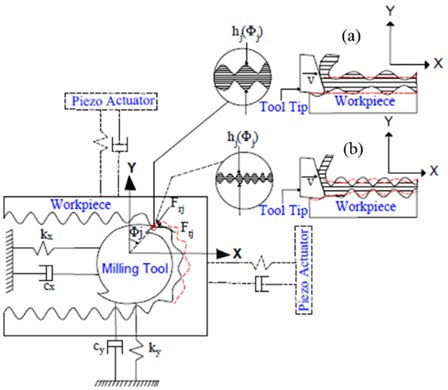
The vibration assisted micro-milling experiments are conducted on a MDA precision machining center with the maximum spindle of 60,000 rpm. Aluminum alloy (AL 6061) workpiece and a two flute carbide tool with the diameter of 3.175 mm and the helix angle of 30° are used. The experimental setup for the micro-milling test is given in Fig. 1 and Fig. 2. A piezo-driven 2-D vibration stage with flexure design is developed, shown in Fig. 1. The maximum travel range of piezoelectric actuator is 15 µm and the frequency is 18 kHz, with the maximum pushing force of 3000 N. The tip of the piezo actuator vibrates with the high frequency voltage provided by the power amplifier. The dynamic property of the vibration stage is experimentally determined by measuring the displacement using the Lion Precision displacement sensor with a bandwidth of 15 kHz and 0.25 nm resolution. It is found that the vibration stage resonates and outputs the maximum vibration amplitude in the frequency range of 5-11 kHz.
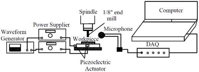
The vibration amplitude of the stage is measured to be 10 µm at the resonance frequency. The workpiece is fixed on the vibration stage. During the milling test, the displacement sensor is used to monitor the real-time vibration of the workpiece. The chatter vibration is monitored using the sound pressure signal measured by a microphone. The sound recorded by the microphone is represented by the voltage and then sent to the data acquisition card. The time-domain voltage signal is converted into frequency domain through FFT to detect the chatter vibration strength.
Fig. 1Experimental setup of vibration assisted micro milling
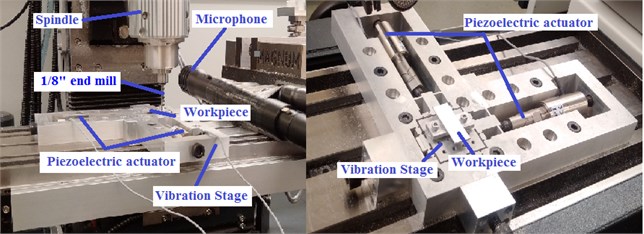
Fig. 2Schematic of the experimental system
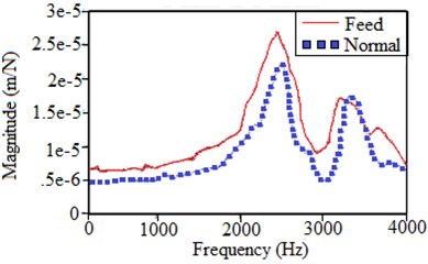
Before selecting the cutting conditions in the micro milling experiment, hammer test is performed on the milling tool to determine the dynamic property of the tool structure. The frequency response functions (FRFs) at the tool tip in both feed and normal directions are measured and plotted in Fig. 3. Based on the FRF results, the chatter stability lobe for the slot milling condition is obtained using the commercial machining simulation and optimization software CutPro [17]. The prediction of chatter stability lobe is based on the analytical zero-order solution proposed by Altintas [18], with the procedure described below:
Chatter frequency is scanned in the range of 0-4000 Hz, which covers the dominant modes of the FRFs shown in Fig. 3. For each chatter frequency, the critical depth of cut is calculated by:
where is the tangential cutting force coefficient for Al 6061. , are the real and imaginary components of the eigenvalues corresponding to the characteristic equation of the dynamic milling process.
Fig. 3FRFs at tool tip in the feed and normal directions
The corresponding spindle speed is calculated by:
where the phase shift between two neighboring waves left on the machined surface is expressed:
The details of the algorithm for predicting the chatter stability using zero-order solution can be found in [18]. The stability lobe corresponding to the experimental setup in this study is shown in Fig. 4.
Fig. 4Chatter stability lobe diagram
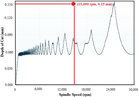
Based on the chatter stability result, the depth of cut (0.15 mm) and spindle speed (15,000 rpm) are selected to intentionally cause strong chatter in the micro milling. Then the vibration assistance is applied on the workpiece, and the sound signals are compared to determine the effect of applied vibration on chatter amplitude. In order to avoid uncertainties during the experiment caused by background sound signal, the tests are performed in the same cutting path for conventional milling and vibration assisted milling.
Table 1Cutting parameters for chatter vibration
Vibration parameters | Frequency (kHz) | 8 |
Amplitude (µm) | 10.3 | |
Feed rate (µm/flute) | 5 | |
Radial depth of cut (mm) | 3.175 | |
Spindle speed (rpm) | 15000 | |
Axial depth of cut (mm) | 0.15 | |
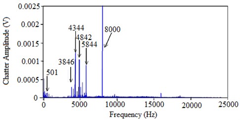
The sound signal collected by the microphone corresponding to the chatter condition based on Fig. 4 is shown in Figs. 5-7, with the values of the cutting parameters listed in Table 1. When chatter occurs, the tool vibration increases until it jumps out of the workpiece, then the dynamic chip generation reaches to the nonlinear region, and the FFT of the cutting sound signal represents the strength of the chatter. Fig. 5 shows the FFT of the background sound signal before the tool is in cutting with the workpiece. It is shown that all the frequency components of the sound signal are below 0.0005. In Fig. 6, the microphone data gives the highest peak at 4342 Hz during the micro milling without vibration assistance. The corresponding spindle and tooth passing frequencies are 250 Hz and 500 Hz, respectively. The other peaks are at the tooth passing frequency harmonics and at the frequency of , which demonstrates the occurrence of regenerative chatter [18]. Fig. 7 shows the sound signal results when the vibration assistance is applied in the micro milling. The chatter frequency, spindle frequency and tooth passing frequency in VAM and CM are the same as shown in Fig. 6 and Fig. 7. However, the chatter amplitude is 0.0032 in CM and 0.00125 in VAM, which shows that the chatter amplitude is reduced by more than 50 %. The peak at 8 kHz in Fig. 7 reflects the sound produced by the piezoelectric actuator, which is not from the cutting process.
Fig. 5Frequency domain signal in air cutting
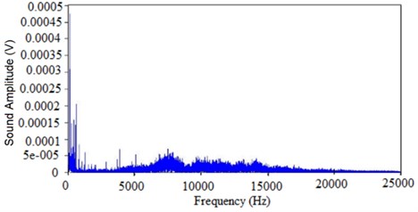
Fig. 6Frequency domain signal for conventional micro milling
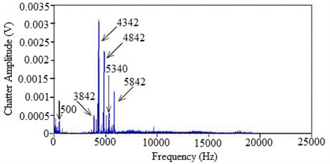
Fig. 7Frequency domain signal in vibration assisted micro milling
3. Experimental results
A series of milling tests were conducted with different cutting conditions and vibration assistance parameters, including vibration direction, amplitude and frequency. The chatter amplitude at each condition is compared between CM and VAM when vibration assistance is applied in 1-D in feed and normal direction respectively as well as in 2-D. The experimental results and the analyses are presented below.
3.1. Chatter amplitude in 1-D vibration assisted milling
The cutting tests are performed when the vibration is applied in feed and normal direction respectively to determine the chatter amplitude between CM and VAM. The effects of the amplitude, frequency, and direction of vibration assistance on the regenerative chatter are studied.
3.1.1. Effect of vibration amplitude on chatter
The cutting parameters in the experiments are listed in Table 2. The frequency of the vibration assistance is 8 kHz, and the amplitude varies in the range of 1-9 µm. Fig. 8 and Fig. 9 show the comparison of chatter amplitude between conventional milling and 1-D vibration assisted milling in feed and normal direction respectively. In order to ensure the repeatability of the results, in each test, three sections of the time-domain vibration signals are picked and converted into frequency domain, with the duration of each section as 2 seconds. The average chatter amplitude between CM and VAM in feed direction and normal direction is compared. It is found that the reduction of average chatter amplitude when the vibration assistance is applied in feed direction is around 33 %, while in the normal direction is 22 %. Therefore, it is concluded that the application of vibration assistance with the amplitude of 1-9 µm is able to effectively reduce the chatter amplitude.
Fig. 8Chatter amplitude with assisted vibration in feed direction
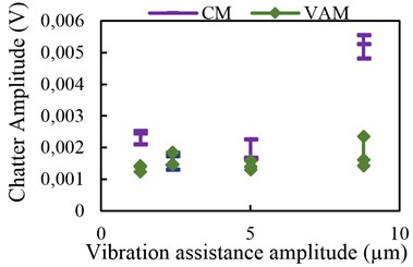
Fig. 9Chatter amplitude with assisted vibration in normal direction
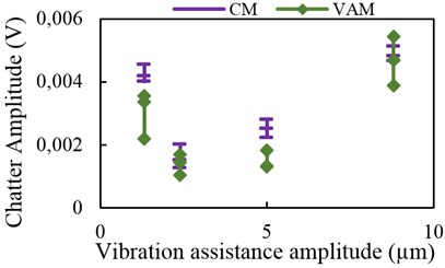
Table 2Cutting parameters with varying vibration amplitude
Vibration parameters | Frequency (kHz) | 8 |
Amplitude (µm) | 1.32, 2.4, 5, 8.82 | |
Feed rate (µm/flute) | 7.5 | |
Radial depth of cut (mm) | 3.175 | |
Spindle speed (rpm) | 10,000 | |
Axial depth of cut (mm) | 0.15 | |
3.1.2. Effect of vibration frequency on chatter
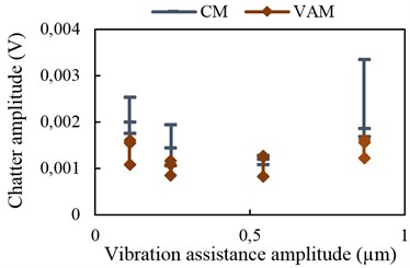
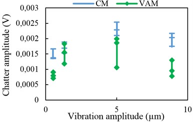
Experiments are also performed when the 1-D vibration assistance is applied at different excitation frequencies, with the measured chatter amplitude shown in Figs. 10-13. The cutting and vibration parameters are given in Table 3. At each frequency, a range of vibration amplitudes are tested depending on the resonating amplitude of the vibration stage. The results show that the chatter amplitude in VAM is reduced by 25-30 % compared to the amplitude in CM. The chatter reduction rate is higher when the vibration amplitude increases. For majority of the measurements, the ratio of the chatter amplitude between CM and VAM increases with the increase of vibration amplitude.
Fig. 10Chatter amplitude with vibration assistance at 9 kHz
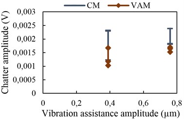
Fig. 11Chatter amplitude with vibration assistance at 8 kHz
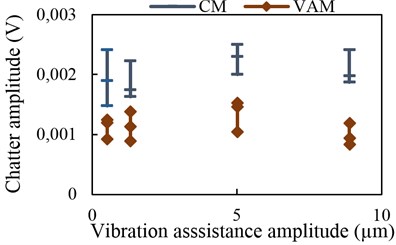
Fig. 12Chatter amplitude with vibration assistance at 7 kHz
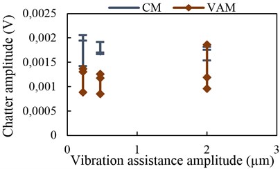
Fig. 13Chatter amplitude with vibration assistance at 5 kHz
3.2. Chatter amplitude in 2-D vibration assisted milling
Experiments are conducted to study the effect of vibration assistance on chatter amplitude when the vibration is applied in two dimensions at the same time. The same cutting and vibration parameters are used for 2-D as in 1-D, shown in Table 3. The results in Figs. 14-17 show that the chatter amplitude in 2-D VAM is significantly lower as compared to the results in CM. The percentage of average chatter reduction in 2-D vibration is 30-44 % which is almost 10 % higher than the results obtained from 1-D vibration. It is concluded that the application of 2-D vibration assistance is able to effectively attenuate the regenerative chatter in the frequency range of 5-9 kHz and the amplitude of 0.1-10 µm.
Table 3Cutting parameters with varying vibration frequency
Vibration parameters | Frequency (kHz) | 5, 7, 8, 9 |
Amplitude (µm) | 0.11-10.3 | |
Feed rate (µm/flute) | 5 | |
Radial depth of cut (mm) | 3.175 | |
Spindle speed (rpm) | 15,000 | |
Axial depth of cut (mm) | 0.15 | |
3.3. Chatter amplitude with feed rate
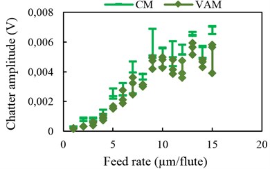
The cutting tests are performed to study the effect of feed rate on chatter amplitude in both CM and VAM. It is generally known that the feed rate doesn’t influence the chatter stability in conventional milling since it only changes the static chip thickness. However, in micro milling process with the feed rate below 15 µm, the tool edge radius is in the same size order of the feed rate, therefore, the relationship between the force and feed rate becomes nonlinear which influences the chatter stability [18]. The cutting parameters used in this test are given in Table 4. All the cutting parameters are constant except feed rate which ranges from 1-15 µm/flute throughout the experiment. Fig. 18 shows the measured chatter amplitude with respect to the feed rate with and without vibration assistance. The results demonstrate that the assisted vibration is able to attenuate the regenerative chatter in the range of feed rate which is typical in the micro milling applications.
Table 4Cutting parameters with feed rate effect
Vibration parameters | Frequency (kHz) | 8 |
Amplitude (µm) | 5 | |
Feed rate (µm/flute) | 1-15 | |
Radial depth of cut (mm) | 3.175 | |
Spindle speed (rpm) | 15,000 | |
Axial depth of cut (mm) | 0.15 | |
Fig. 14Chatter amplitude with 2-D vibration assistance at 9 kHz
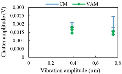
Fig. 15Chatter amplitude with 2-D vibration assistance 8 kHz
4. Analysis and discussions
Fig. 19 shows the schematic of the conventional milling and vibration assisted milling processes. Regenerative chatter occurs due to the dynamic chip formation when tool tip trajectories in two consecutive passing periods are out of phase [18]. Part (a) in Fig. 19 shows the chip formation in CM, while Part (b) shows the chip formation in VAM.
Fig. 16Chatter amplitude with 2-D vibration assistance at 7 kHz
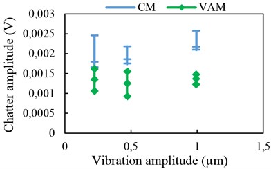
Fig. 17Chatter amplitude with 2-D vibration assistance at 5 kHz
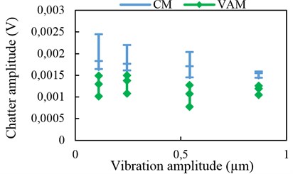
Fig. 18Chatter amplitude with respect to the feed rate
The dynamics of the milling system are described by the equations of motion:
where the dynamic chip thickness is composed of three parts: the static value , dynamic value caused by milling tool’s vibration , and the component influenced by assisted vibration applied on the workpiece , expressed as:
where each component is expressed as:
The tool’s vibration , are determined by the dynamic cutting force obtained in Eq. (4), while the vibration of workpiece is provided by the piezo-actuator, and given as:
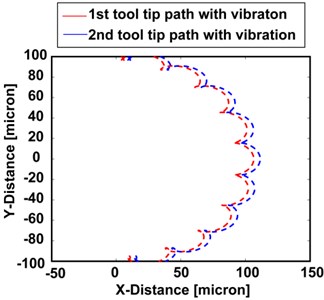
In this experiment, the chatter frequency in conventional milling is 4342 Hz as shown in Fig. 6. The application of vibration assistance at frequency above 5000 Hz modifies the instantaneous dynamic chip thickness. Since the amplitude of the workpiece vibration is in the same level with the feed rate, the assisted vibration could result into the tool’s jumping out of the cutting area, thus the dynamics becomes nonlinear and the regenerative chip formation mechanism completely changes as a result of the vibration assistance. Furthermore, Fig. 20 shows cutting tool’s trajectories relative to the workpiece in two consecutive tooth passing periods in the vibration assisted machining process. It is found that the instantaneous chip thickness could reach very small value at certain cutting location. Therefore, modification of tool tip trajectory by adding vibration assistance reduces the dynamic cutting force by reducing the dynamic chip thickness.
Fig. 19Schematic of chip formation in (a) CM and (b) VAM
Moreover, the damping coefficient in the equations of motion Eq. (4) is composed of the structural damping as well as the process damping, expressed as:
Shown in Part (b) of Fig. 19, the contact between the tool’s flank face and the work surface contributes to the process damping effect in the machining process. The application of 2-D vibration assistance at higher frequency compared to the original chatter frequency reduces the wavelength of the surface. Since the process damping force is inversely proportional to the wavelength [19], the application of high frequency vibration assistance decreases the wavelength, therefore increases the process damping force to a certain extent. As a result, the chatter amplitude reduces. However, quantitative analysis requires the calibration of process damping coefficient for Al 6061, and is not in the scope of this experimental study.
Fig. 20Relative cutting tool’s trajectory in two consecutive tooth passing periods in VAM
5. Conclusions
This paper presents the experimental study on the chatter attenuation in vibration assisted micro-milling of Al 6061. A 2-D vibration stage driven by piezoelectric actuators and flexure design is developed. Experimental modal test is conducted on the milling tool, and the cutting conditions are selected to intentionally cause chatter vibration. The chatter signal is measured by microphone, and the chatter amplitudes with and without vibration assistance are compared and analyzed. The following conclusions are drawn based on this study:
1) The developed vibration stage is able to generate 2-D vibration on the workpiece in the frequency range of 5-10 kHz with the amplitude of 1-10 µm, which is comparable to the typical feed rate values in micro milling process. Therefore, the assisted vibration significantly influences the dynamic chip thickness in the micro milling process.
2) The experimental results demonstrate that the average chatter amplitude is attenuated by 20 %-33 % when vibration assistance is provided in 1-D with a series of frequencies and amplitudes, while the chatter amplitude reduces by up to 44 % when the vibration assistance is provided in 2-D. It is because the applied vibration modifies the dynamic thickness therefore changes the regenerative mechanism in the chip formation. Furthermore, higher frequency of applied vibration compared to the chatter vibration increases the process damping. The chatter amplitude decreases as a result.
3) The experimental results show that the applied vibration assistance attenuates regenerative chatter in a range of feed rate values, with which the relationship between the force and the chip thickness becomes nonlinear in the micro milling process. This experimental study demonstrates that the 2-D vibration assistance is able to effectively attenuate the high frequency regenerative chatter in the micro milling process.
References
-
Jin X., Altintas Y. Chatter stability model of micro-milling with process damping. Journal of Manufacturing Science and Engineering, Transactions of the ASME, Vol. 135, Issue 3, 2013, p. 31011-31011.
-
Moradi H., Gholamreza V., Mehdi B., Mohammad R. M. Vibration absorber design to suppress regenerative chatter in nonlinear milling process: application for machining of cantilever plates. Applied Mathematical Modelling, Vol. 39, Issue 2, 2015, p. 600-620.
-
Madoliat R., Hayati S., Ghalebahman A. G. Investigation of chatter suppression in slender endmill via a frictional damper. Scientia Iranica, Vol. 18, Issue 5, 2011, p. 1069-1077.
-
Wang M. Feasibility study of nonlinear tuned mass damper for machining chatter suppression. Journal of Sound and Vibration, Vol. 330, Issue 9, 2011, p. 1917-1930.
-
Yang Y., Muñoa J., Altintas Y. Optimization of multiple tuned mass dampers to suppress machine tool chatter. International Journal of Machine Tools and Manufacture, Vol. 50, 2010, p. 834-842.
-
Lin S. C., Hu M. R. Low vibration control system in turning. International Journal of Machine Tools and Manufacture, Vol. 32, Issue 5, 1992, p. 629-640.
-
Mei Z., Yang S., Shi H., Chang S., Ehmann K. F. Active chatter suppression by on-line variation of the rake and clearance angles in turning – principles and experimental investigations. International Journal of Machine Tools and Manufacture, Vol. 34, Issue 7, 1994, p. 981-990.
-
Frumusanu Gabriel R., Constantin I., Marinescu V., Epureanu A. Development of a stability intelligent control system for turning. International Journal of Advanced Manufacturing Technology, Vol. 64, Issues 5-8, 2013, p. 643-657.
-
Soliman E., Ismail F. Chatter suppression by adaptive speed modulation. International Journal of Machine Tools and Manufacture, Vol. 37, Issue 3, 1997, p. 355-369.
-
Kubica E. G., Ismail F. Active suppression of chatter in peripheral milling. Part II. application of fuzzy control. The International Journal of Advanced Manufacturing Technology, Vol. 12, Issue 4, 1996, p. 236-245.
-
Rashid A., Nicolescu C. Active vibration control in palletised workholding system for milling. International Journal of Machine Tools and Manufacture, Vol. 46, Issues 12-13, 2006, p. 1626-1636.
-
Kaliński J., Marek C., Mazur M., Galewski M. Vibration surveillance system with variable stiffness holder for milling flexible details. Applied Non-Linear Dynamical Systems, 2014, p. 175-184.
-
Xiao M., Karube S., Soutome T., Sato K. Analysis of chatter suppression in vibration cutting. International Journal of Machine Tools and Manufacture, Vol. 42, Issue 15, 2002, p. 1677-1685.
-
Tabatabaei S. M. K., Behbahani S., Mirian S. M. Analysis of ultrasonic assisted machining (UAM) on regenerative chatter in turning. Journal of Materials Processing Technology, Vol. 213, Issue 3, 2013, p. 418-425.
-
Yao Z., Mei D., Chen Z. Chatter suppression by parametric excitation: model and experiments. Journal of Sound and Vibration, Vol. 330, Issue 13, 2011, p. 2995-3005.
-
Ma C., Ma J., Shamoto E., Moriwaki T. Analysis of regenerative chatter suppression with adding the ultrasonic elliptical vibration on the cutting tool. Precision Engineering, Vol. 35, Issue 2, 2011, p. 329-338.
-
CUTPRO™. Advanced Milling Process Simulation System. www.malinc.com. 2013.
-
Altintas Y. Manufacturing Automation: Manufacturing Automation: Metal Cutting Mechanics, Machine Tool Vibrations, and CNC Design. Cambridge University Press, UK, 2012.
-
Altintas Y., Jin X. Mechanics of micro-milling with round edge tools. CIRP Annals – Manufacturing Technology, Vol. 60, Issue 1, 2011, p. 77-80.
About this article

