Abstract
This paper presents a new adaptive multi-grid method for analyses on damage and failure in concrete column under cyclic loading. Self-adaptation of the method can carry out automatically coupling analysis on the process of evolving damage to structural failure with dynamic grid-change due to damage, without user intervention in the computation. The theory of multi-grid FEM coupled evolving damage is developed on the basis of the improved variational principle to consider damage evolution, in which the elements in each sub-domain with different grid sizes are under the different state of damage. Then the multi-grid FEM method is provided with the theory and a 3D adaptive mesh refinement procedure. As a case study of the method, the process of evolving damage to failure of a concrete column under cyclic loading is simulated by using the developed method, and the simulated results fit well with the experimental data. The results show that, the developed method is reliable in simulation on evolving damage and failure in concrete column under dynamic seismic loading with lower cost and sufficient precision.
1. Introduction
The failure of the engineering structures will inevitably lead to disaster results during the service period, especially for a deadly earthquake. So the study on damage and failure mechanism of the important engineering structures under seismic loading has attracted the attention of researchers and engineers, especially for concrete structures which are widely used in civil engineering structures. Actually, the process of damage evolution to failure in concrete structures appears as an irreversible process from material damage in concrete of stress concentration zone to local failure in vulnerable component and eventually to structural failure. So, in order to study well failure mechanism of concrete structures under seismic loading, it is necessary to consider the dynamic process of damage evolution up to failure.
Many works have been done on the seismic analysis of engineering structures. Mansour observed the behavior of reinforced concrete elements under cyclic loading [1, 2]. Jafari studied the behavior of rock joints under dynamic and cyclic loadings based on experiment [3]. Elnashai applied three assessment tools of testing, analysis and field observations, and their combination to investigate vulnerability of structures under seismic loading [4]. Murray evaluated the potential shear failure of the columns seismic and the structure’s ability to resist progressive collapse [5]. Khan presented a seismic risk analysis of cable stayed bridge based on the concept of damage probability matrix [6]. Zoubek analyzed the failure mechanism of beam-to-column dowel connections under seismic loading [7]. Ghobarah proposed a method for damage assessment of structures under seismic loading based on the change in stiffness of the structure, which is better suited for non-linear structural analysis [8]. Scotta proposed two series of indexes, which respectively are Global Damage Indexes (GDIs) and Section Damage Indexes (SDIs). They are respectively to evaluate seismic performance of overall structure and reinforced concrete beam-column sections [9]. Kamaris proposed a damage index for plane steel frames under seismic loading, which takes into account the interaction between the axial force and bending moment acting on the section of steel member [10].
In the above methods to evaluate seismic behavior of engineering structures, few previous methods can reveal the failure mechanisms by considering the dynamic process from material damage in concrete of stress concentration zone to local failure in vulnerable component and eventually to structural failure. But in order to better understanding dynamic seismic failure mechanisms of engineering structures, it is necessary to consider the dynamic coupling process.
Therefore, this paper aims to develop a new adaptive multi-grid method for simulating the process of damage evolution to failure of concrete structures with lower cost. In the developed method, the material damage can be delineated based on the concept of continuum damage mechanics (CDM), which uses a damage variable to describe the deterioration process of materials due to initiation and growth of defects such as micro-cracks or micro-voids [11, 12]. The theory of multi-grid FEM coupled evolving damage is first developed on the basis of the improved variational principle to consider damage evolution, in which the elements in each sub-domain with different grid sizes are under the different state of damage. Then the multi-grid FEM method is proposed with the theory and a 3D adaptive mesh refinement procedure, by which the FE elements can be refined to smaller scales adaptively, once the damage value in an element reaches its critical value. At last, a numerical example of evolving damage to failure of a concrete column under dynamic cyclic loading is given by using the developed method.
2. Theory of multi-grid FEM coupled evolving damage
Hu–Washizu variational principle is a well-known variational principle without any constraint, which is used to derive FEM when restricted to discrete sets of displacements, strains and stresses that are possibly discontinuous across element boundaries [13]. Since the sub-domains can be adaptively generated from the developed multi-grid FEM method, it is suitable as a basic equation for the discontinuous across sub-domains boundaries. To give the FE formulation for describing the trans-scale process of evolving damage to structural failure and adaptive FE mesh refinement process, we start with the general Hu-Washizu functional [14]:
where is the volume of a body subjected to the action of distributed body force ( 1, 2, 3), is the boundary surface subjected to the action of external surface force , is the boundary surface where the displacement ( 1, 2, 3) is given, is the displacement tensor, is the strain tensor, is the strain energy density, is Lagrangian multiplier defined in the , is Lagrangian multiplier defined on the . In Eq. (1), there are four kinds of independent variables of variation, , , , without any constraint condition.
2.1. Improved Hu–Washizu variational principle to consider evolving damage
To describe damage evolution process, the damage variable is substituted into Eq. (1), then the Eq. (1) can be rewritten as:
In Eq. (2), there are five kinds of independent variables of variation, , , , , . The body of concrete material can be approximately considered as elastic body in macro-scale [15]. And the strain energy density coupling damage of elastic body can be written as [16]:
where is the Cauchy stress tensor [16], is the initial elastic stiffness tensor. According to the concept of effective stress, the effective stress tensor can be expressed as [16]:
Substituting Eqs. (3)-(4) into Eq. (2) and carrying out the variation of Eq. (2) with respect to the five independent variables, , , , , , we can obtain:
In Eq. (5), the symbol denotes variation. Based on variational principle , we can obtain:
Substituting Eq. (3), Eq. (6), and Eq. (9) into Eq. (2), the modified Hu-Washizu functional coupling brittle damage can be expressed as:
When , Eq. (12) can be rewritten as:
And the Eq. (13) is the original Hu-Washizu functional obtained from the minimum potential energy principle by using Lagrange multiplier method to remove the constraints [14].
2.2. Multi-grid FEM from the improved variational principle coupling damage
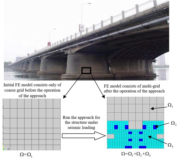
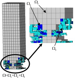
The calculated results of damage analysis using FEM considerably depend upon FE mesh [17, 18]. Meanwhile, to describe accurately the pattern of the initiation and growth of local failure within structure, the refinement grid is required. If using traditional methods for the whole small-scale simulation, this often leads to consume a lot of computation time and even make the analysis impossible. To overcome the difficulty, a 3D adaptive mesh refinement procedure is developed and implemented in the method. Based on the procedure, FE elements can be refined to smaller scales adaptively, once the damage value in an element reaches its critical value. Namely the grid of the computational domain can adaptively be refined more precisely while the damage of the domain is more serious. So sub-domain with different grid sizes can be adaptively generated and changed with the damage evolution using the procedure. For example, for one concrete bridge, as shown in Fig. 1, before operation of the method, the initial FE model consists only of (grey domain with the coarsest grid). The damage evolution can be divided into three stages based on the damage level, namely , and , which respectively are described using , and . Under seismic loading, when the damage value of one element in reaches the preset with damage evolution, the element can be adaptively refined into 8 elements which belong to (blue grid). When the damage value of one element in reaches the preset with damage evolution, the element can be adaptively refined into 8 elements which belong to (green grid). After the operation of the method for the structure under seismic loading, the initial computational domain can be adaptively decomposed into three sub-domains based on the split criterion coupled in the method.
In the adaptive FE mesh refinement process, the multi-grid domains are automatically implemented into the improved variational principle coupling damage. The sum of functionals of all sub-domains and interfaces can be expressed as:
where is the functional of sub-domain (1, 2, 3), is the functional of interface between the boundary of and the boundary of (), is the functional of interface between the boundary of and the boundary of (), is the functional of interface between the boundary of and the boundary of (). A weak form of the interface displacement continuity is incorporated by using Lagrange multipliers on the interfaces.
Based on Eq. (12), Eq. (14) can be rewritten as:
where is the volume of the sub-domain , delineates the interface between boundary surface subjected to the action of external surface force and the boundary of , delineates the interface between boundary surface where displacement is given, and the boundary of , , and are respectively displacement components of elements on the boundary of , and , is Lagrange multiplier.
The new functional in Eq. (15) is established by absorbing damage and sub-domains with different grid sizes into the original Hu-Washizu functional. Based on variational principle and carrying out the variation of Eq. (15), we can obtain:
And all FE equations and governing equations can be obtained from the variational equality Eq. (16).
Fig. 1Adaptive split criterion
3. Adaptive multi-grid FEM for damage evolution and failure in concrete structures
As discussed in Section 1, the failure of structure involves many coupled processes, from material damage in concrete of stress concentration zone to local failure in vulnerable component and eventually to structural failure. In order to study the failure mechanism of structures, the three major patterns, which respectively are material damage evolution, initiation and growth of local failure in macro-scale and structural global failure, should be described in the method.
3.1. Description on material damage evolution in the method
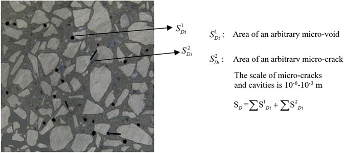
The degradation of the properties of materials is due to the growth and coalescence of micro-cracks or micro-voids [11]. Using a damage variable to delineate the degradation behavior of material had widely accepted since the early time of Kachanov for its convenience of calculation. As shown in Fig. 2 captured by computerized tomography, the micro-cracks and micro-voids give rise to a reduction of macroscopic stiffness or strength which is described using a continuous damage based on the concept of continuum damage mechanics (CDM) herein:
where is the overall sectional area of representative volume element (RVE), is the total area of the micro-cracks and micro-voids. The effective stress is deduced from the Cauchy stress by taking into account the effective section due to the micro-cracks and micro-voids. This is written as:
Fig. 2Concrete RVE with micro-cracks and voids
The effective stress concept is based on the measured macroscopic behavior of the damaged medium. Based on the concept, many concrete damage models have been developed. In this paper, the concrete damage model proposed by Mazars [20] is adopted to describe the macroscopic effect of degradation on the mechanical behavior of concrete using a damage variable :
where is the strain threshold of damage, are model parameters, (, is the principal strain).
3.2. Description on initiation and growth of local failure in structure in the method
When the damage of element 1, the element is considered to be failure. In order to obtain the relatively accurate position and growth path of local failure area, FE meshes consisting of a lot of elements are necessary when using traditional method in single scale. This often leads to consume a lot of computation time and even make the analysis impossible. Therefore, in this paper a 3D adaptive mesh refinement procedure is developed and implemented in the method to describe the process from small-scale local failure area to large-scale local failure area until the structural failure with sufficient precision and lower cost. By using the method coupled with the procedure, the elements can be refined to smaller scales adaptively without user intervention in the computation, once their damage values reach preset value.
3.3. The criteria for structural failure in the method
When structure under the given loads loses bearing capacity, it is considered to be failure. For example, when the structure is failure with accumulation of the material damage and local failure area, the loading direction force of the load point is close to 0 even if the displacement loading acting on the load point is very large, while the loading direction displacement of the load point is very large even if the force loading acting on the load point.
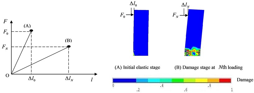
To quantify the global seismic damage state of structure, a global damage index of structures is developed based on the load-displacement curve, which reflects the degradation of the mechanical behavior:
where , are respectively the load and displacement of the load point of the structure at th loading, , are respectively the initial load and displacement of the load point, when the global structure is in elastic stage, as shown in Fig. 3. And a procedure for monitoring is implemented in the method. Once the reaches 1, the concrete column is considered to be failure, while the method saves the failure time and exits automatically.
Fig. 3Schematic diagram of global damage index
3.4. The main procedure of the method
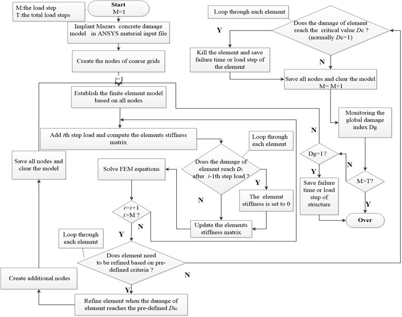
The main flow chart of the method is given in Fig. 4. In the developed adaptive multi-grid method, the trans-scale process of evolving damage to structural failure can be delineated. And FE elements can be refined to smaller scales adaptively with accumulation of damage.
Fig. 4Main flow chart of the whole adaptive multi-grid FEM
4. Numerical analysis on failure of a concrete column under dynamic cyclic loading
4.1. Numerical example
In order to study the seismic failure mechanism of concrete structures, collapse experiments of concrete frame structure and its key columns under cyclic loading were carried out by Tsinghua University [21]. As an example, since the behavior of columns in earthquakes is very important [22], the key large-scale concrete column is chosen in this paper to simulate its failure process under the specified experiment condition in Ref. [21] using the developed method, as shown in Fig. 5. The dimension of the concrete column is 200 mm × 200 mm × 850 mm.
Fig. 5Test setup of concrete column under dynamic loading [21]
![Test setup of concrete column under dynamic loading [21]](https://static-01.extrica.com/articles/16209/16209-img5.jpg)
And the load spectrum is shown in Fig. 6. As shown in Fig. 6, the total cycle number of loading is 38. And after the 38th cyclic loading, the concrete column is failure [21]. In the first six cycles, the loads are controlled with horizontal force loading. And all levels of the horizontal force loading are in the following order: 10, 20, 30 KN, which are recycled twice. While in the last thirty-two cycles, the load is controlled with horizontal displacement loading. And all levels of horizontal displacement loading are in the following order: 10, 15, 20, 25, 30, 37.5, 45, 55 mm, which are recycled four times [21].
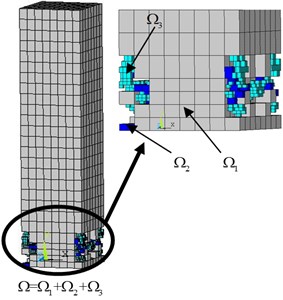
The initial FE model is shown in Fig. 7(a). And is the cycle number of loading, is the failure number of loading cycles, 38 for the concrete column under the cyclic loading. And the adaptive FE mesh refinement process with the cycle ratio based on the adaptive split criterion coupled in the developed method is shown in Fig. 7.
Fig. 6Load spectrum
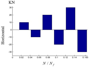
a) Horizontal force loading
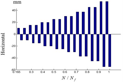
b) Horizontal displacement loading
Fig. 7Adaptive finite element mesh refinement process with the cycle ratio
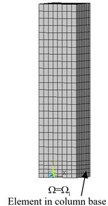
a) Initial FE model consists only of coarse grid at the cycle ratio
b) FE model consists of multi-grid at the cycle ratio 29/38
c) FE model consists of multi-grid at the cycle ratio 1
4.2. Numerical simulation of the dynamic damage process and experimental validation
As shown in Fig. 8, for studying the seismic failure mechanism of concrete structures, the failure evolution pattern of the concrete column under cyclic loading is simulated by using the developed method. The results of simulation agree well with the experimental results, which imply that the method is reliable in simulation on dynamic evolving seismic damage and failure in concrete structures. The location of the initiation and growth of local failure area within the concrete column predicted by simulation is verified through experiment.
Fig. 8Comparison between calculation and experimental results
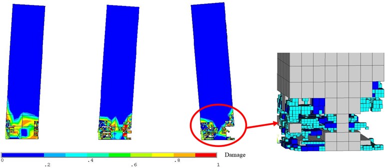
a) Calculation result at the cycle ratio: 29/38, 33/38, 1
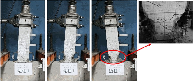
b) Experimental result at the cycle ratio 29/38, 33/38, 1
The horizontal force and displacement of the load point predicted by simulation and experiment are respectively given in Fig. 9 and Fig. 10. For the numerical example, before 3/19, the loads are controlled with horizontal force loading, while the loads are controlled with horizontal displacement loading after 3/19. So the horizontal force of the load point before 3/19 and displacement of the load point after 3/19 for simulation are the same as the experimental results, which are known before the simulation. And therefore, Fig. 9 is provided to verify the predicted the horizontal force of the load point by the method after 3/19, and Fig. 10 is provided to verify the predicted the horizontal displacement of the load point by the method before 3/19. As shown in Fig. 10, the predicted the horizontal displacement of the load point agrees well with the experimental results. As shown in Fig. 9, with increasing load, the horizontal force of the load point continues to decrease after 13/19 with the accumulation of the material damage and local failure area. The horizontal force of the load point is close to 0 when 1. This is verified through experiment. So the trend of the horizontal force of the load point with cycle ratio predicted by the method is similar to the experimental result, although there are disparities on the result of the horizontal force of the load point obtained from simulation and experiment. There are many causes of error. For example, the highly complex trans-scale failure mechanism cannot be completely contained in the method. And the damage model cannot completely reflect the behavior of material damage. Similarly, it may also be due to the measuring error under the limitation of the experimental condition, or the real constraints for experimental condition cannot be completely reflected in simulation.
Although there are somewhat disparities due to the complexity of trans-scale failure mechanism and some objective factors, the predicted results can fit well with experimental results. It insinuates that the proposed method is reliable.
Fig. 9Comparison between calculation and experimental results of the horizontal force of the load point
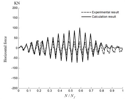
Fig. 10Comparison between calculation and experimental results of displacement of the load point
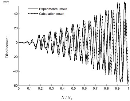
Fig. 11Global damage index of the concrete column under the cyclic loading
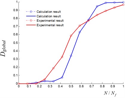
The global damage index of the concrete column under the cyclic loading can be calculated based on monitoring data respectively obtained from the method and experiment using Eq. (20), as shown in Fig. 11. When the global damage index reaches 1, the concrete column is considered to be failure.
5. Conclusions
The following specific conclusions can be obtained from the present study:
1) This work proposed a new method for simulating damage evolution up to failure in concrete structures under seismic loading. The unique feature of the method is the numerical description on the dynamic coupling process from material damage in concrete of stress concentration zone to local failure in vulnerable component and eventually to structural failure.
2) Another feature of the proposed multi-grid FEM method is that the FE elements can be refine adaptively with the increase of damage values, so that the elements in each sub-domain with different grid sizes are under the different state of damage. The adaptive capability enables the mesh of the computational domain to be refined automatically more precisely while the damage in the area is more severe, without user intervention.
3) The developed method has been successfully applied to simulate the dynamic process of evolving damage to failure of a concrete column under cyclic loading. And the simulated results fit well with the experimental data even though a little error exists due to the complexity of failure mechanism. It is shown that the developed method can be used to reveal the failure mechanism of concrete structures by considering the dynamic coupling process from material damage in concrete of stress concentration zone to local failure in vulnerable component and eventually to structural failure.
4) The results suggest that, the developed method is reliable in simulation on dynamic evolving damage and failure in concrete structures under seismic loading with the adaptive capability as well as better computational efficiency, so that may be applied to analysis on seismic damage and failure of large concrete structures.
References
-
Mansour M., Hsu T. T. C. Behavior of reinforced concrete elements under cyclic shear. I: experiment. Journal of Structural Engineering, Vol. 131, Issue 1, 2005, p. 44-53.
-
Mansour M., Hsu T. T. C. Behavior of reinforced concrete elements under cyclic shear. II: theoretical model. Journal of Structural Engineering, Vol. 131, Issue 1, 2005, p. 54-65.
-
Jafari M. K., Pellet F., Boulon M., Hosseini A. K. Experimental study of mechanical behavior of rock joints under cyclic loading. Rock Mechanics and Rock Engineering, Vol. 37, Issue 1, 2004, p. 3-23.
-
Elnashai A. S. Assessment of seismic vulnerability of structures. Journal of Constructional Steel Research, Vol. 62, 2006, p. 1134-1147.
-
Murray J. A., Sasani M. Seismic shear-axial failure of reinforced concrete columns vs. system level structural collapse. Engineering Failure Analysis, Vol. 32, 2013, p. 382-401.
-
Khan R. A., Datta T. K., Ahmad S. Seismic risk analysis of modified fan type cable stayed bridges. Engineering Structures, Vol. 28, 2006, p. 1275-1285.
-
Zoubek B., Isakovic T., Fahjan Y., Fischinger M. Cyclic failure analysis of the beam-to-column dowel connections in precast industrial buildings. Engineering Structures, Vol. 52, 2013, p. 179-191.
-
Ghobarah A., Elfath H. A., Biddah A. Response-based damage assessment of structures. Earthquake Engineering and Structural Dynamics, Vol. 28, 1999, p. 79-104.
-
Scotta R., Tesser L., Vitaliani R., Saetta A. Global damage indexes for the seismic performance assessment of RC structures. Earthquake Engineering and Structural Dynamics, Vol. 38, Issue 8, 2009, p. 1027-1049.
-
Kamaris G. S., Hatzigeorgiou G. D., Beskos D. E. A new damage index for plane steel frames exhibiting strength and stiffness degradation under seismic motion. Engineering Structures, Vol. 46, 2013, p. 727-736.
-
Kachanov L. M. On the time to under creep condition. Izvestia Akademi Nauk USSR, Vol. 8, 1958, p. 26-31, (in Russian).
-
Ibijola E. A. On some fundamental concepts of continuum damage mechanics. Computer Methods in Applied Mechanics and Engineering, Vol. 191, 2002, p. 1505-1520.
-
Eyck A. T., Lew A. Discontinuous Galerkin methods for non-linear elasticity. International Journal for Numerical Methods in Engineering, Vol. 67, 2006, p. 1204-1243.
-
Chien W. C. Method of high-order Lagrange multiplier and generalized variational principles of elasticity with more general forms of functional. Applied Mathematics and Mechanics, Vol. 4, Issue 2, 1983, p. 143-157.
-
Feng R., Xia M. F., Ke F. J., Bai Y. L. Adaptive mesh refinement FEM for damage evolution of heterogeneous brittle media. Modelling and Simulation in Materials Science and Engineering, Vol. 13, 2005, p. 771-782.
-
Lemaitre J. A Course on Damage Mechanics. Springer, New York, 1996.
-
Labergère C., Rassineux A. A., Saanouni K. K. 2D adaptive mesh methodology for the simulation of metal forming processes with damage. International Journal of Material Forming, Vol. 4, 2011, p. 317-328.
-
Toi Y., Hasegawa K. Element-size independent, elasto-plastic damage analysis of framed structures using the adaptively shifted integration technique. Computers and Structures, Vol. 89, 2011, p. 2162-2168.
-
Loland K. E. Continuum damage model for load response estimation of concrete. Cement and Concrete Research, Vol. 10, 1980, p. 395-402.
-
Mazars J., Pyaudier-Cabot G. Continuous damage theory – application to concrete. Journal of Engineering Mechanics, Vol. 115, Issue 2, 1989, p. 345-365.
-
Lu X. Z., Ye L. P., Pan P., Tang D. Y., Qian J. R. Pseudo-static collapse experiments and numerical prediction competition of RC Frame structure II: key elements experiment. Building Structure, Vol. 42, Issue 11, 2012, p. 23-26, (in Chinese).
-
Dogan M. Failure analysis of shear columns to seismic events. Engineering Failure Analysis, Vol. 18, 2011, p. 682-693.
About this article

The work described in this paper was substantially supported by A Project Funded by the Priority Academic Program Development of Jiangsu Higher Education Institutions (No. CE02-2-46), National Natural Science Foundation of China (No. 11072060).
