Abstract
Based on anatomical features of a 50th percentile adult male, three-dimensional (3D) finite element (FE) models of ribs, sternum, vertebrae, intervertebral discs, clavicle, scapula, pelvis, skin, head, muscles and limbs were developed in this study. After integrating/assembling various organs and tissues, a bio-mechanical FE model of the human body with adult male characteristics was produced. Furthermore, a chest frontal and lateral collision theory model was built and was validated by using previously published data from corpse frontal and lateral chest impact collision experiments. Good agreements were found between the simulation results of our model and the experimental data as well as theoretical calculations in the contact force, sternum displacement, and force-displacement response. These data suggest that this 3D FE model is effective and has good bio-fidelity in assessing chest biomechanical responses and thoracic injuries upon impact loading. Therefore this model can potentially be useful for evaluating thoracic injuries in car crashes and assessing chest rib fractures and internal organ/tissue damages.
1. Introduction
Along with the more scientific, comprehensive and stringent requirements of the more advanced automotive industry, new research questions and challenges have been raised in the mechanics of human impact trauma injuries. Through human injury biomechanics studies, data can be obtained on biomechanical responses and resilience of various tissues or organs of the human body during and following the collision course, which can be used to develop appropriate injury classification criteria, and design more anthropomorphic and realistic research dummies. Ultimately, through conducting dummy collision experiments and assessing the damages to the dummy, the car's safety can be improved [1]. As the global population ages and there are more elderly drivers, the incidence and mortality from chest injuries are increasing [2, 3]. Currently, chest injuries in the elderly drivers cannot be accurately assessed and distinguished by the current legal evaluation criteria [4]. Thus, more in-depth studies are required with the chest impact load dynamic responses [5].
In the past few decades, experimental tests of chest impact injuries have been carried out with post mortem human subjects (PMHS) [6-9]. However, due to the considerable time involvement and ethical concerns, in the present time, such experiments have been very difficult to carry out. The biomechanical model is thus the most scientific and effective alternative to solve such problems. As one major musculoskeletal organ structure protecting the internal organs, mechanisms of chest and rib damages have increasingly attracted attention of researchers. A rib fracture upon collision under load is one evaluation index for serious chest injuries [10], and research that has been carried out so far has been mainly on material properties of experimental research ribs [11]. While three-point bending tests and tensile tests of the ribs have been the most common and most effective way to study the rib material properties [12], researchers have also conducted a number of simulation studies [13, 14]. Studies related to rib fractures have shown that simulation is an effective method to investigate rib material characteristics and biomechanics, as the extents of damage can be analyzed by changing the simulation parameters. However, low velocity impact responses of the entire chest and rib fractures under load have been less studied [15]. For the automotive crash safety concern, to understand and appropriately assess the damage responses of the entire chest in the case of a low velocity collision is essential and vital because seat belt is the only protection mechanism to passengers under this situation, and the car frontal crash safety and seat belt regulations are all established based on the overall response of the entire chest.
In this study, an effective biomechanical model of the adult male human thorax was therefore established and validated using data from reported corpse experiments and conducted simulations for the low speed front and side crashes. Finally, the validated model is used to verify the impact of the loads on chest injury and rib fractures.
2. Materials and methods
2.1. Human biomechanics finite element (FE) model
Through computer tomography (CT) scanning (slice thickness of 0.6 mm) of the head and neck, chest and abdomen, upper and lower limbs and other body tissues of a 35-year-old 50th percentile male of medium-build characteristics (height 172 mm and weight 72 kg), DICOM data and precise geometric information of human tissues were obtained. Using 3D tomographic CT image reconstruction technology, the correctly aligned slices were stacked to build 3D models of body organs/tissues and their geometries. Using the medical modelling software MIMICS to build the model, Fig. 1 shows the head and chest-abdominal CT scan images. To produce a smooth surface geometric surface model, with the GEOMAGIC software, CT point cloud images were processed for noise reduction, filtering and smoothing according to the selected point cloud image accuracy, so that they were aligned the best way to fit in and between the surface layers.
Fig. 1Human body computed tomography (CT) scan images
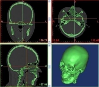
a) Head and neck CT scans
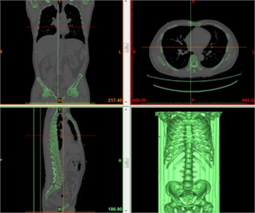
b) Chest and abdominal CT scans
Then, the accurate surface model was developed by using Germanic Studio 12.0 (Geomanic, Research Triangle Park, NC, USA). Subsequently, the model was meshed using Hypermesh 11.0 (Altair Engineering, Inc., Troy, Michigan, USA). Finally, it was developed into the adult human head 3D FE model. In addition, for simulation, analysis and calculation were conducted using LS-DYNA 971 (Livermore Software Technology Corporation, Livermore, California, USA).
The entire model contains about 300 components, 905762 nodes and 1038760 units and weighs 72 kg. The element numbers and element types of the human finite element model are shown in Table 1. The model also describes the anatomical structures of the main tissues of the human chest (Fig. 2).
Table 1Element number and element type of the human finite element model
Components | No. of elements | Element type | |
Head | Scalp | 12772 | Solid (SectSld) |
Compact bone of cranial bone | 24638 | Solid (SectSld) | |
Cancellous bone of cranial bone | 9844 | Solid (SectSld) | |
Facial bone | 6010 | Solid (SectSld) | |
Dura mater | 4826 | Shell (SectShll) | |
Pia mater | 4826 | Shell (SectSld) | |
Cerebrospinal fluid | 9852 | Solid (SectSld) | |
Cerebrum | 24502 | Solid (SectSld) | |
Cerebellum | 8512 | Solid (SectSld) | |
Brainstem | 1792 | Solid (SectSld) | |
Corpus callosum | 944 | Solid (SectSld) | |
Falx cerebri | 601 | Shell (SectShll) | |
Tentorium cerebelli | 462 | Shell (SectShll) | |
Pituitary Gland | 448 | Solid (SectSld) | |
Ear | 544 | Shell (SectSld) | |
Thorax | Cortical bone of ribs | 23917 | Shell (SectSld) |
Cancellous bone of ribs | 23287 | Solid (SectSld) | |
Sternum cortical bone | 2726 | Shell (SectSld) | |
Sternum cancellous bone | 4267 | Solid (SectSld) | |
Vertebrae cortical bone | 46032 | Shell (SectSld) | |
Vertebrae cancellous bone | 76012 | Solid (SectSld) | |
Rib cartilage | 8915 | Solid (SectSld) | |
Disc | 13460 | Solid (SectSld) | |
Intercostal muscle | 25601 | Shell (SectSld) | |
others | 16504 | Shell (SectSld) | |
Limbs | Upper compact bone | 25126 | Shell (SectSld) |
Upper cancellous bone | 26546 | Solid (SectSld) | |
Lower limb cortical bone | 32500 | Shell (SectSld) | |
Lower limb cancellous bone | 96731 | Solid (SectSld) | |
Others | 8945 | Solid (SectSld) | |
Abdomen | Pelvic cortical bone | 20086 | Shell (SectSld) |
Pelvic cancellous bone | 24775 | Solid (SectSld) | |
Sacrum compact bone | 18843 | Shell (SectSld) | |
Sacrum cortical bone | 28465 | Solid (SectSld) | |
Others | 15621 | Solid (SectSld) | |
Internal organs | Skin | 19500 | Shell (SectSld) |
Muscle | 64476 | Solid (SectSld) | |
Heart | 8802 | Solid (SectSld) | |
Lung | 33654 | Solid (SectSld) | |
Liver | 11106 | Solid (SectSld) | |
Stomach | 12798 | Solid (SectSld) | |
Intestine | 5951 | Solid (SectSld) | |
Kidney | 5552 | Solid (SectSld) | |
Septum | 1697 | Shell (SectSld) | |
Vascular / bronchus | 1868 | Shell (SectSld) | |
Others | Joints and ligaments | 124200 | Solid (SectSld) |
Total | 1038760 |
Fig. 2An entire human finite element model
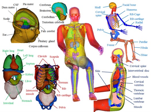
Table 2Human bony elastic/plastic material parameters [1-4, 16-20]
Anatomy structure | Density (g/cm3) | Young’s modulus (GPa) | Poisson’s ratio | Yield strength (MPa) | Tangent modulus (GPa) | Hardening parameters | Cowper-Symonds parameters | Plastic failure strain (%) | |
C | P | ||||||||
Cortical bone ribs | 2 | 11.5 | 0.3 | 120 | 1.15 | 0.1 | 2.5 | 7 | 2 |
Cancellous bone ribs | 1 | 0.04 | 0.45 | 2.2 | 0.01 | 0.1 | 2.5 | 7 | 3 |
Sternum cortical bone | 2 | 12 | 0.3 | 120 | 1.15 | 0.1 | 2.5 | 7 | 2 |
Sternum cancellous bone | 1 | 0.04 | 0.3 | 2.2 | 0.01 | 0.1 | 2.5 | 7 | 3 |
Cervical cortical bone | 2 | 12 | 0.3 | 100 | – | – | – | – | – |
Cervical cancellous bone | 1 | 1 | 0.3 | 8.3 | – | – | – | – | – |
Upper cortical bone | 2 | 11 | 0.3 | 110 | – | – | – | – | – |
Upper cancellous bone | 1 | 1.1 | 0.3 | 7.7 | – | – | – | – | – |
Lower limb cortical bone | 2 | 18.5 | 0.3 | 146 | – | – | – | – | – |
Lower limb cancellous bone | 1 | 0.15 | 0.45 | 30.6 | – | – | – | – | – |
Pelvic cortical bone | 2 | 17 | 0.29 | 180 | – | – | – | – | – |
Pelvic cancellous bone | 1 | 0.07 | 0.4 | 70 | – | – | – | – | – |
Sacrum cortical bone | 2 | 17 | 0.29 | 180 | – | – | – | – | – |
Sacrum cancellous bone | 1 | 0.07 | 0.29 | 70 | – | – | – | – | – |
For the chest FE model, material parameters of the various tissues were based on published experimental data on tissue materials from other researchers as well as parameters selected from some existing human biomechanical models in the literature [1-4, 12-13, 16-23]. For the bone tissues, the constitutive elastic/plastic model was used. For skin, cartilage, blood vessels, bronchial and other, the linear elastic material model were used. For intervertebral discs, muscles, heart, lungs and other soft tissues, a viscoelastic material model was employed. The body's main bony elastic/plastic material parameters are shown in Table 2. The chest and abdominal tissue linear elastic/viscoelastic material parameters are shown in Table 3, and head material parameters are shown in Table 4.
Table 3Chest and abdomen linear elastic/viscoelastic material parameters [1, 2, 12, 13, 21, 22]
Anatomy structure | Density (kg/m3) | Young’s modulus (GPa) | Poisson’s ratio | Short shear modulus (kPa) | Long shear modulus (kPa) | Bulk modulus (MPa) |
Rib cartilage | 1600 | 1.2 | 0.2 | – | – | – |
Vascular / bronchus | 1000 | 0.5 | 0.45 | – | – | – |
Skin | 1000 | 0.035 | 0.42 | – | – | – |
Muscle | 1100 | – | – | 140 | 40 | 1.33 |
Heart | 1000 | – | – | 20 | 75 | 0.22 |
Lung | 600 | – | – | 67 | 65 | 2.19 |
Disc | 1040 | – | – | 32 | 18 | 307 |
Table 4Head material parameters [23, 24]
Head anatomy structure | Density, (kg/m3) | Young’s modulus, (MPa) | Poisson’s ratio, | Shear modulus (kPa), | Decay constant, (s-1) | Bulk modulus, (GPa) |
Scalp | 1000 | 16.7 | 0.42 | |||
Compact bone of Cranial bone | 2000 | 15000 | 0.22 | |||
Cancellous bone of Cranial bone | 1300 | 1000 | 0.24 | |||
Facial bone | 5000 | 21000 | 0.23 | |||
Dura mater | 1130 | 31.5 | 0.23 | |||
Pia mater | 1130 | 11.5 | 0.45 | |||
Cerebrospinal fluid | 1000 | 0.49 | 50 | 2.19 | ||
Cerebrum | 1040 | 1.66, 0.928 | 16.95 | 5.57 | ||
Cerebellum | 1040 | 1.66, 0.928 | 16.95 | 5.57 | ||
Brainstem | 1040 | 1.66, 0.928 | 16.95 | 5.57 | ||
Corpus callosum | 1140 | 31.5 | 0.45 | |||
Falx cerebri | 1140 | 31.5 | 0.45 | |||
Tentorium cerebelli | 1140 | 31.5 | 0.45 | |||
Pituitary Gland | 1140 | 31.5 | 0.45 | |||
Ear | 1000 | 16.7 | 0.42 |
2.2. Front and side thorax theoretical models
Lobdell established a simplified chest frontal impact mathematical lumped mass model [25] as shown in Fig. 3. is the mass of the impactor, wherein the initial velocity is known. The total mass of the sternum and the ribs of the surrounding portion of the chest is . The sum of the mass of thoracic spine and the entire spine-related body mass connected by a collision impact is . Spring constant between the impactor and the sternum represents the skin and muscle elasticity. The mass and the mass exhibit viscous and elastic properties. They are represents the resilience of the ribs and the damping effect provided by the surrounding structures as well as the heart and lungs. A paralleled material model (, ) also indicates viscoelasticity of the chest. The responses of its each part can be calculated by Eqs. (1)-(4), in which the formula parameters used are shown in Table 5:
Table 5Theory model parameters [25]
23.4 kg | 0.47 kg | 27.2 kg | 2.81 kN/cm | 0.263 kN/cm | 0.132 kN/cm | 0.52 kN/m | 1.23 kN/m | 0.18 kN/m |
Fig. 3Thorax collision theory models [25]
![Thorax collision theory models [25]](https://static-01.extrica.com/articles/16324/16324-img4.jpg)
2.3. Chest frontal crash test model validation
Validation of the chest finite element model established above was carried out mainly utilizing published data from previous corpse body impact tests. For low-speed and high-mass car frontal collision, the references of Kroell (1971, 1974) and other studies were used. These low-speed crash impact tests used cylindrical wooden body impactors of ~1.64-23.59 Kg and 15.24 cm diameter and a group of 38 corpses [26]. In these experiments, 4.9-14.3 m/s initial velocity impact was used to hit the middle of the sternum between the fourth rib and the fifth rib, with corpse’s arms being constrained in horizontal positions. The impact force was measured by a load cell installed on the impactor, and the deformation of the chest was recorded by using a high-speed camera. For the purpose of analyzing the chest injuries, basic anthropometric data for the five male corpses are shown in Table 6, which were used for the 6.7 m/s and 23.4 kg impactor impact tests.
Table 6Chest front crash test sample data [26]
Experiment numbers | Age | Mass (kg) | Chest thickness (mm) |
15 | 80 | 53 | 200 |
18 | 78 | 66 | 219 |
19 | 19 | 66 | 203 |
20 | 29 | 57 | 203 |
22 | 72 | 75 | 225 |
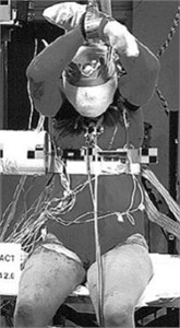
Frontal crash simulation was defined as the impact of the impactor at 6.7 m/s initial velocity hitting the sternum between the fourth and fifth ribs. The corpse was set in a sitting position with arms restraint, and the rigid impactor was 15.24 cm in diameter and 23.4 kg in weight. When the wooden impactor hit the chest, the impactor did not deform substantially. To match the contact force of skin contact during the experiment, the type of skin contact with the impactor was defined as Contact-Automatic-Surface-to-Surface, and the friction coefficient was set at 0.3. The type of contact among chest muscle, ribs and chest muscles surfaces was defined as Contact-Tied-Surface-to-Surface, and the friction coefficient was set at 0.3. The type of contact of the entire human tissue was defined as Contact-Automatic-Single-Surface, and the friction coefficient was set at 0.2. The chest frontal impact experimental test and simulation are shown in Fig. 4.
Fig. 4Kroell frontal crash test and simulation
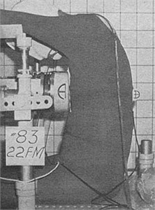
a) Tests [26]
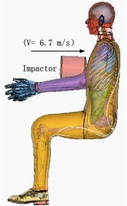
b) Simulation
2.4. Chest side impact simulation
So far, PMHS body side impact tests have been carried out [29], which used a wood impactor of 50 kg in weight and 152.4 mm in diameter impacting on the lateral center of the sternum of the sixth rib while the corpse body movement was restricted. For the side impact simulation, the impactor was defined as a rigid body with the loading condition of 5.6 m/s initial velocity hitting the side of the chest. Similarly, simulation time was 60 ms and the corpse was set in a sitting position with arms/hands restraint. The rigid impactor was 15.24 cm in diameter and 50 kg in weight. The chest side impact experimental test and simulation are shown in Fig. 5.
Fig. 5Side impact test and simulation
a) Tests [27]
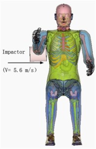
b) Simulation
3. Results and discussion
In the chest frontal or lateral collision simulation with the impact having the 6.7/5.6 m/s initial velocity, the time course speed changes of the impactor are shown in Fig. 6. After touching the chest, impactor speed decreased rapidly, reaching a minimum of 32/38 ms. It slowed down mainly due to the absorption of the impact energy by the body resulting from deformation of the body’s various tissues. When the speed reached a minimum after nearly 0.2/0.5 m/s, the energy generated by the impact was fully absorbed by the body. After this point, chest muscles and ribs generated a certain rebound force, causing the rebound velocity increasing to 2 m/s at the end of the impact process.
Fig. 6Time course changes of impact velocity of the impactor
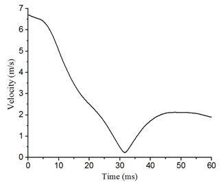
a) Front
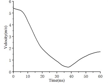
b) Side
Time course changes of the chest breastbone and ribs were also simulated following the frontal collision impact (Fig. 7). Fig. 7(a) shows the simulated results at 15, 30, 45, and 60 ms following the impact. At the early stage (0-15 ms) chest started to show deformation. At 30 ms, the deformation of the chest reached the maximum. During 30-60 ms, the chest displayed the rebound process. Fig. 7(b) shows the sternum and rib fracture states at the time with the maximum deformation at the front of the chest. As shown, although there were no obvious signs of completely broken bones in the chest or ribs, the 2nd, the 3rd, and the 4th ribs, the breastbone and some cartilage showed signs of fractures.
In addition, the simulation also produced a sternum force - displacement curve, with the output nodes set at the centers of the impactor and the sternum, and the simulation results have been compared with experimental test results [26] (Fig. 7(c)). It can be seen that the simulated impact force-displacement curve is between the upper and lower limits of the experimental curves. Through comparisons of the experimental and simulation results for the chest front impact, a good correspondence of the chest front impact force – deformation relationship can be observed. These comparisons indicate that our simulation results are consistent with published data of corpse experiments [26]. Furthermore, when compared with the calculation results of a theoretical model [25], our simulation results show a similar trend of chest impact responses. These data indicate that our simulation model has a good validity in predicting biomechanics responses and chest injuries following a frontal collision.
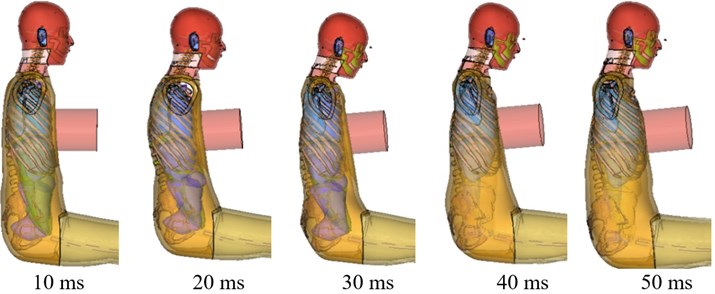
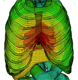
Similarly, time course changes in the chest were also simulated following the lateral collision impact (Fig. 8). Fig. 8(a) shows the simulation results at 10, 20, 30, 40, and 50 ms following the impact. At the early stage (0-10 ms), the chest started to deform. During 10-50ms, the deformation reached the maximum. During 50-60 ms, the chest rebounded. At the time with the maximum deformation at the side of the chest, rib fracture state (Fig. 8(b)) showed signs of displaced fractures of the 7th, 8th, and 9th ribs.
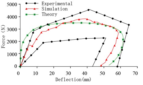
Comparison between our simulation results of the sternum force-displacement curve with the published experimental data with corpses [27] also shows that the simulated sternum force curve sits in between the upper and lower limits of the experimental results [27] for the chest side impact (Fig. 8(c)). Again, by comparing the theoretical model [25], the experimental [27] and simulation results, a close similarity of the side impact force-deformation relationship can be observed. These comparisons suggest that our simulation model also has a good validity in predicting biomechanics responses and chest injuries following a side collision.
Fig. 7Simulation of chest front impact biomechanical responses, fracture state, and impact force-deformation curve
a) Chest front impact biomechanical responses at 10, 20, 30, 40, or 50 ms after impact
b) Chest front impact rib fracture status
c) Chest front impact force – deformation curve
Fig. 8Simulation of chest side impact biomechanical responses, fracture state, and impact force-deformation curve
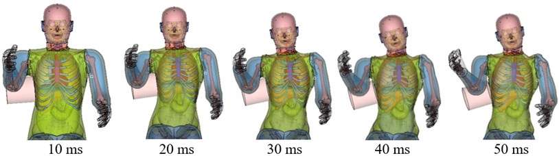
a) Side-impact thorax biomechanical response
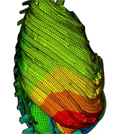
b) Side impact rib fracture status
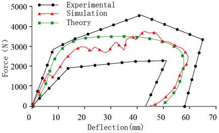
c) Side impact force – deformation curve
4. Conclusion
In this study, a 3D FE model of the chest based on anatomical features of a 50th percentile adult male was developed. This model was validated by using previously published data from corpse chest impact experiments of the front and side chest impact collisions, where good agreements were found between the experimental data and our model simulation in force-displacement response in the collisions. This validated model was found to be able to accurately simulate characteristics of chest rib fractures and soft tissue injuries. Therefore, this validated 3D FE chest model can be potentially useful for investigating human chest injuries under front or side impact loading.
References
-
Yang K. H., King A. I. Development of an anthropomorphic numerical surrogate for injury reduction (ANSIR). Journal of Mechanics in Medicine and Biology, Vol. 4, Issue 4, 2004, p. 447-461.
-
Anderson A. E., Peters C. L., Tuttle B. D., et al. Subject-specific finite element model of the pelvis: development, validation and sensitivity studies. Transactions of the ASME-K, Journal of Biomechanical Engineering, Vol. 127, Issue 3, 2005, p. 364-373.
-
King H. Yang, Jingwen Hu, Nicholas A. White, Albert I. King Development of numerical models for injury biomechanics research: a review of 50 years of publications in the Stapp Car Crash Conference. Stapp Car Crash Journal, Vol. 50, 2006, p. 429-490.
-
Kitagawa Y., Yasuki T. Correlation among seatbelt load, chest deflection, rib fracture and internal organ strain in frontal collisions with human body finite element models. IRCOBI Conference Proceedings, 2013, p. 282-316.
-
Kemper A. R., Kennedy E. A., McNally C., et al. Reducing chest injuries in automobile collisions: rib fracture timing and implications for thoracic injury criteria. Annals of Biomedical Engineering, Vol. 39, Issue 8, 2011, p. 2141-2151.
-
Mohan Radhakrishna, Ioli Makriyianni, Judith Marcoux, Xun Zhang Effects of injury level and severity on direct costs of care for acute spinal cord injury. International Journal of Rehabilitation Research, Vol. 37, Issue 4, 2014, p. 349-353.
-
Baudrit P., Petitjean A., Potier P., et al. Comparison of the thorax dynamic responses of small female and midsize male post mortem human subjects in side and forward oblique impact tests. Stapp Car Crash Journal, Vol. 58, 2014, p. 103-21.
-
Petit P., Trosseille X., Dufaure N., et al. The effect of upper body mass and initial knee flexion on the injury outcome of post mortem human subject pedestrian isolated legs. Stapp Car Crash Journal, Vol. 58, 2014, p. 197-211.
-
Yoganandan N., Humm J., Pintar F. A., et al. Lateral neck injury assessments in side impact using post mortem human subject tests. Annals of Advances in Automotive Medicine/Annual Scientific Conference. Association for the Advancement of Automotive Medicine, Vol. 55, 2011, p. 169-79.
-
Rikard Fredriksson, Jaeho Shin, Costin D. Untaroiu Potential of pedestrian protection systems – a parameter study using finite element models of pedestrian dummy and generic passenger vehicles. Traffic Injury Prevention, Vol. 12, Issue 4, 2011, p. 398-411.
-
Li Z., Kindig M. W., Subit D., et al. Influence of mesh density, cortical thickness and material properties on human rib fracture prediction. Medical Engineering and Physics, Vol. 32, Issue 9, 2010, p. 998-1008.
-
Zhou Q., Rouhana S. W., Melvin J. W. Age effects on thoracic injury tolerance. SAE Technical Paper 962421, Proceedings of the 40th Stapp Car Crash Conference, Albuquerque, New Mexico, USA, 1996.
-
Cai Z., Lan F., Chen J. Development and validation of a human biomechanical model for rib fracture and thorax injuries in blunt impact. Computer Methods in Biomechanics and Biomedical Engineering, Vol. 18, Issue 9, 2015, p. 974-980.
-
Wang F., Yang J., Miller K., et al. Numerical investigations of rib fracture failure models in different dynamic loading conditions. Computer Methods in Biomechanics and Biomedical Engineering, 2015, p. 1-11, (in Press).
-
Leport T., Baudrit P., Potier P., et al. Study of rib fracture mechanisms based on the rib strain profiles in side and forward oblique impact. Stapp Car Crash Journal, Vol. 55, 2011, p. 199-250.
-
Kleinman P. K., Schlesinger A. E. Mechanical factors associated with posterior rib fractures: laboratory and case studies. Pediatric Radiology, Vol. 27, Issue 1, 1997, p. 87-91.
-
Li Z., Kindig M. W., Kerrigan J. R., et al. Rib fractures under anterior-posterior dynamic loads: experimental and finite-element study. Journal of Biomechanics, Vol. 43, Issue 2, 2010, p. 228-234.
-
Kemper A. R., Kennedy E. A., Mcnally C., et al. Reducing chest injuries in automobile collisions: rib fracture timing and implications for thoracic injury criteria. Annals of Biomedical Engineering, Vol. 39, Issue 8, 2011, p. 2141-2151.
-
Kindig M., Li Z., Kent R., et al. Effect of intercostal muscle and costovertebral joint material properties on human ribcage stiffness and kinematics. Computer Methods in Biomechanics and Biomedical Engineering, Vol. 18, Issue 5, 2015, p. 556-70.
-
Kleinman P. K., Schlesinger A. E. Mechanical factors associated with posterior rib fractures: laboratory and case studies. Pediatric Radiology, Vol. 27, Issue 1, 1997, p. 87-91.
-
Li Z., Kindig M. W., Kerrigan J. R., et al. Rib fractures under anterior–posterior dynamic loads: experimental and finite-element study. Journal of Biomechanics, Vol. 43, Issue 2, 2010, p. 228-234.
-
Kemper A. R., Kennedy E. A., McNally C., et al. Reducing chest injuries in automobile collisions: rib fracture timing and implications for thoracic injury criteria. Annals of Biomedical Engineering, Vol. 39, Issue 8, 2011, p. 2141-2151.
-
Kwong Ming Tse, Siak Piang Lim, et al. A review of head injury and finite element head models. American Journal of Engineering, Technology and Society, Vol. 1, Issue 5, 2014, p. 28-52.
-
Wenyi Yan, Oscar Dwiputra Pangestu A modified human head model for the study of impact head injury. Computer Methods in Biomechanics and Biomedical Engineering, Vol. 14, Issue 12, 2011, p. 1049-1057.
-
Lobdell T. E., et al. Impact Response of the Human Thorax. Human Impact Response. Springer, New York, US, 1973, p. 201-245.
-
Kroell C. K., Schneider D. C., Nahum A. M. Impact tolerance and response of the human thorax II. Stapp Car Crash Conference Proceedings. SAE Paper 741187, 1974.
-
Chung J., Cavanaugh J. M., et al. Thoracic injury mechanisms and biomechanical responses in lateral velocity pulse impacts. 43rd Stapp Car Crash Conference, San Diego, California, 1999.
About this article

ZC is supported by National Natural Science Foundation of China (51405153), and the Key of Planned Science and Technology Project of Hunan Province, China (2015NK3031). LW is supported by Australian National Health and Medical Research Council (NHMRC) Postgraduate Research Scholarship grant, and CJX is supported by the NHMRC Senior Research Fellowship.
Study design: Zhihua Cai and Liping Wang. Study conduct: Liping Wang and Cory J. Xian. Data collection: Zhihua Cai, Zemin Li and Zhihui Xiao. Data analysis: Zhihua Cai and Zemin Li. Data interpretation: Zhihua Cai and Zemin Li. Drafting manuscript: Zhihua Cai and Liping Wang. Revising manuscript content: Zhihua Cai, Liping Wang, HungYao Hsu and Cory J. Xian. All authors have read and approved the final submitted manuscript.
