Abstract
In order to design a suitable control scheme for human extremity exoskeleton, the interaction force control scheme which regards human body as the work environment of human extremity exoskeleton was proposed. And then, the electromechanical system of human extremity exoskeleton was simplified, and the modeling and simulation study of the electromechanical system by using Matlab/Simulink module was carried out. The angular deviations between human extremity exoskeleton joints and human body joints were obtained by the simulation. Besides, the torques provided by human body and motors for human extremity exoskeleton joints to bear heavy payload were calculated. The analysis of the simulation calculation results proves that the interaction force control scheme can achieve good man-machine coordinated walking as well as help human body bear heavy payload. Besides, the upper extremity exoskeleton experiment was conducted, and the same conclusion with the simulation study was obtained.
1. Introduction
Human extremity exoskeleton is a kind of wearable intelligent robot [1] that has capability of carrying a payload and can supplement human intelligence with the strength. It can be used for the soldiers to bear heavy payload when marching [2], so it can reduce the burden of the pilot in real time. Besides, it’s capable of transporting heavy materials over rough terrain or up staircases.
At present, the research of human extremity exoskeleton is very hot in the global scope. The earlier human extremity exoskeleton developed by University of Berkeley called BLEEX [3, 4], the BLEEX has 7 revolute DOF per leg and four of which are powered by linear hydraulic actuators. H. Kazerooni [5] et al. proposed the sensitivity amplification control method (belong to the position control method) for the BLEEX that can increase the closed loop system sensitivity to its pilot’s forces and torques without any measurement from the pilot. But the control method has little robustness to parameter variations and therefore requires a relatively good dynamic model of the system. The exoskeleton developed by Tomoyoshi Kawabata et al. of Tsukuba University called HAL [6], HAL produces torque corresponding to muscle contraction torque by referring to the myoelectricity that is biological information to control operator’s muscles. For each half, left and right, joints of the lower half part of the exoskeleton are achieved by three single-axis revolute joints. The human extremity exoskeleton developed by K. H. Low [7] et al. of Singapore Nanyang Technological University called NTU that uses the ZMP control strategy. It can offer some guidance for the research of the stability of human extremity exoskeleton. Besides, the quasi passive walking was applied to the research of human extremity exoskeleton to improve energy utilization by the Biomechatronics Group of Massachusetts Institute of Technology [8]. Now there are more than 10 human extremity exoskeleton research institutions in China. The typical human extremity exoskeleton developed by Naval Aeronautical Engineering Institute called NES. The knee joint of NES is driven by a rope connected with the motor output shaft [2]. In addition, some human extremity exoskeletons are researched to be used in the treatment for the disabled [9, 10].
The position control method, trajectory planning and ZMP stability criterion are all usually used in the research of traditional robot [11]. However, years of research and development experience of human extremity exoskeleton show that those traditional methods will cause poor man-machine interaction. Although they can barely achieve the synchronous walk of human extremity exoskeleton with human body, but the walking posture will become not very nature. However, force control method is increasingly applied to the control scheme of humanoid robot in recent years [12].
So the interaction force control scheme based on the current control loop of motor was proposed in this paper. The human body will be regarded as a work environment of the human extremity exoskeleton. The target is to keep the interaction forces between human extremity exoskeleton and human body environment small, so the good man-machine coordinated walking will be realized. Besides, this article provides a simulation method for studying the electromechanically system of human extremity exoskeleton, and the same job has never been done by anyone else. By modeling and simulation study of the electromechanical system of human extremity exoskeleton, the feasibility of the design can be effectively analyzed as well as the development cost of human extremity exoskeleton can be reduced.
2. Interaction force control scheme for human extremity exoskeleton
The humanoid design which is recognized by most researchers is adopted here. The designed human extremity exoskeleton contains 3 degrees of freedom of the hip, 1 degree of freedom of the knee, 3 degrees of freedom of the ankle. The designed upper extremity exoskeleton contains 3 degrees of freedom of the shoulder, 1 degree of freedom of the elbow, 3 degrees of freedom of the wrist. And all the degrees of freedom for walking direction of them are actuated [5, 13]. The man-machine coupling schematic diagram is shown in Fig. 1.
Fig. 1Man-machine coupling schematic diagram of human extremity exoskeleton
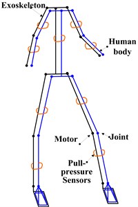
By adding pull-pressure sensors to the connection part of the human extremity exoskeleton to detect the interaction forces as well as to bundle the human extremity exoskeleton with human body. The human extremity exoskeleton is just used to assist human body bearing heavy payload when working, the human body still has to provide some power for the movement of payload.
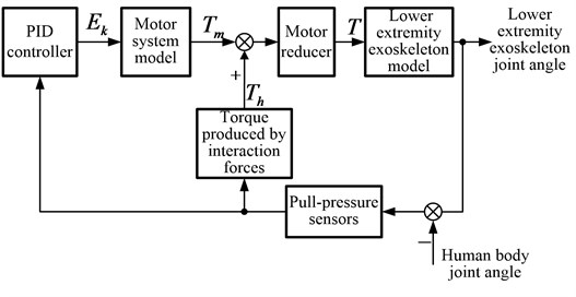
By setting the motor controller to work in the current control loop so as to control the motor torque directly. In this case, the motor speed will be in a passive state. After the interaction forces are detected by the pull-pressure sensors, the sensor signals will be processed and amplified by the PID controller. At last, the processed and amplified signals will be used to control the motor torque directly. The block diagram of interaction force control scheme is shown in Fig. 2.
When the movement of human extremity exoskeleton is not completely consistent with human body, the interaction forces will necessarily be detected by the pull-pressure sensors. And then the human extremity exoskeleton will be controlled to obey the movement of human body by the PID controller, so the interaction forces will have a tendency to become smaller. Thus the good man-machine coordinated walking will be achieved.
Fig. 2Block diagram of interaction force control scheme
3. Establishment of the model
3.1. Establishment of the human extremity exoskeleton model
3.1.1. Simplification of the human extremity exoskeleton model
For one single leg of human extremity exoskeleton, it can be divided into two modes: the support leg and the swinging leg. Because only the 3 degrees of freedom for walking direction are actuated, the human extremity exoskeleton model is always simplified as plane model [2]. The support leg mode starts from the ankle joint and contains 3 connecting rods: thigh, shank and trunk in turn. The swinging leg mode starts from the hip joint and also contains 3 connecting rods: shank, thigh and foot in turn. Strictly speaking, the support leg and the swinging leg will affect each other. However, the trunk needs to bear heavy payload which will make the weight of trunk connecting rod be 10 times of other connecting rods, this will result in the affection be too small to be considered. So no matter what mode the legs are, they can both be regarded as three connecting rod models. Just like the swinging leg, the arms can of course be regarded as three connecting rod models.
Fig. 3The simplified models and coordinate systems
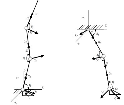
The system coordinate system usually used for the movement of human body is as follows: the axis points to the forward direction of human body, the axis is vertical upward, and the axis can be determined by the right hand rule. The local coordinate system of each joint of the human extremity exoskeleton is defined as follows: the axis is from each joint point to the next joint; the axis is parallel to the plane of the system coordinate system; the axis can be determined by the right hand rule. The simplified models and coordinate systems of the two modes are shown in Fig. 3.
3.1.2. Model of the human extremity exoskeleton
In turn, to calculate out the coordinate transformation matrix; velocity; angular velocity; gravitational potential energy and kinetic energy of each joint of the human extremity exoskeleton. And then, according to the Lagrange equation, the torques of joints of the human extremity exoskeleton can be obtained by using the symbolic toolbox of Matlab to calculate [14]:
Remove the variable: and so In the same way: , .
Assuming , , .
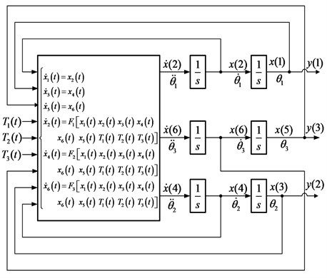
So the differential equations of state of the human extremity exoskeleton are:
According to the differential equations, the human extremity exoskeleton model (as shown in Fig. 4) which can express the relationship of each joint torque with each joint angular acceleration, angular velocity and angle can be established.
Fig. 4The human extremity exoskeleton model
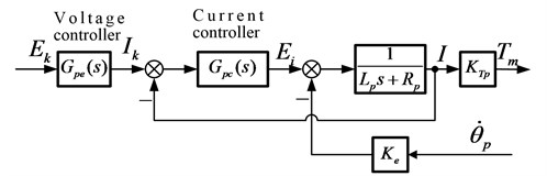
3.2. Establishment of the motor system model
According to the Kirchhoff’s law, the voltage balance equation of permanent magnet synchronous motor is:
The induction motor voltage is proportional to the magnetic flux and the angular velocity:
The motor torque is proportional to the armature current :
The motor controller is set to work in the current control loop, so the motor output torque is approximate proportional to the input voltage signal of the controller. The motor system model is shown in Fig. 5.
Fig. 5The motor system model
3.3. Establishment of the man-machine interaction model
According to the simplification of the human extremity exoskeleton model, all the upper and lower extremities of exoskeleton can be regarded as three connecting rod models. The schematic diagram for analyzing the interaction force is shown in Fig. 6.
Fig. 6The schematic diagram for analyzing the interaction force
When the movement of human extremity exoskeleton is not completely consistent with the human body, there will be a relative displacement . According to the Voight model [15] for the surface of human body, the relative displacement will lead to a resistance: . denotes the stiffness of the surface of body, denotes the damping coefficient.
The bind location is set in the center of each connecting rod. Due to all the angular deviations are very small, so approximately:
So, all the relationships between interaction forces () and angular deviations () can be established.
3.4. Overall model of the electromechanical system
The overall model of the electromechanical system can be established by connecting the human extremity exoskeleton model, the motor system model, the man-machine interaction model and the PID controller together. Besides, the PID controller parameters should be adjusted to be appropriate.
Fig. 7The overall model of the electromechanical system
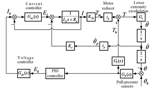
The interaction forces are caused by the deviations of human body joint angles () and human extremity exoskeleton joint angles , and the interaction forces will be detected by the pull-pressure sensors. Then, the sensor signals will be processed and amplified to be the motor control signals () by the PID controller. At last, the human extremity exoskeleton will be driven to obey the movement of human body.
4. Simulation
4.1. Simulation model
The simulation parameters are set as shown in Table 1.
Notes: I rod means first connecting rod; II rod means second connecting rod; III rod means third connecting rod.
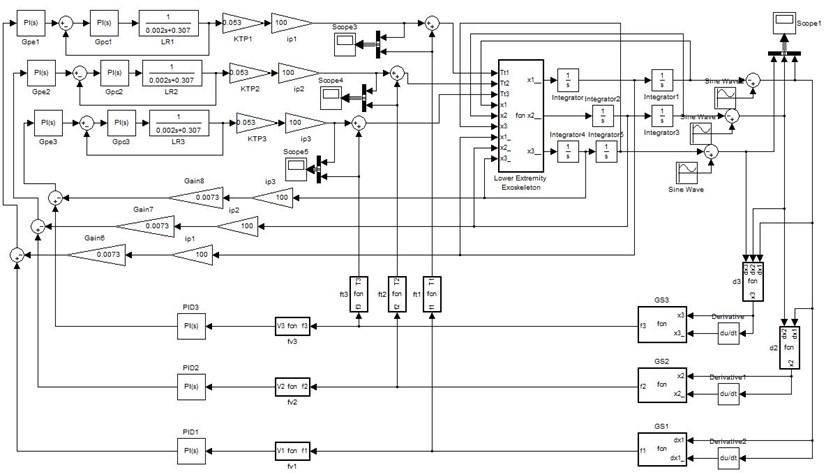
The Matlab/Simulink simulation model can be easily established according to the overall model of the electromechanical system.
All the three driving curves of human body joints are set as 0.4 rad (22.9°) amplitude sine curve: rad.
Table 1The simulation parameters
I rod length | 0.39 m | II rod length | 0.41 m |
III rod length | 0.5 m | I rod weight | 0.7 kg |
II rod weight | 0.7 kg | III rod (with payload) weight | 15.5 kg |
I rotational inertia | 0.01 kg∙m2 | II rod rotational inertia | 0.0154 kg∙m2 |
III rod (with payload) rotational inertia | 0.081 kg∙m2 | Gravitational acceleration | 9.8 m/s2 |
Motor inductance | 0.002 H | Motor resistance | 0.307 Ω |
Reduction ratio | 100 | Current controller | 10+5 s |
Voltage controller | 4/10+1/10 s | Stiffness of the surface of body | 1 Nm/m |
Damping of the surface of body | 8 Nm∙s/m | Motor torque coefficient | 0.053 N∙m/A |
Motor magnetic flux | 0.0073 | ||
Fig. 8Matlab/Simulink simulation model
4.2. Analysis of the simulation results
4.2.1. Driving torque
Simulating in the condition of bearing 15 kg payload (the third connecting rod weighs 15.5 kg), the obtained driving torques are shown in Fig. 9.
It can be seen from the figure that the driving torques provide by motors are more than 10 times of that provide by human body. It means most of the torques for human extremity exoskeleton joints to bear heavy payload were provided by motors. So it proves that the interaction force control scheme can help human body bear heavy payload.
4.2.2. Angular deviation
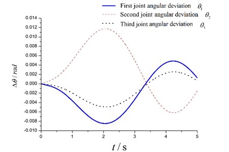
The angular deviations of human extremity exoskeleton joints with human body joints that are obtained by simulating are shown in Fig. 10.
Because of the similarity of the three drive curves, the largest angular deviations of the three joints appear at the same time. It can be seen from Fig. 10 that all the three largest angular deviations are very small, the largest first joint angular deviation is –0.009 rad (about 0.52°); the largest second joint angular deviation is 0.012 rad (about 0.69°); the largest third joint angular deviation is –0.005 rad (about 0.29°). So: –1.76 mm; –1.06 mm; 0.16 mm. In other words, it means the human extremity exoskeleton can track the human body very well. So it proves that the interaction force control scheme can achieve good man-machine coordinated walking.
Fig. 9Driving torque provide by human body/ motor (left/right) for human extremity exoskeleton joints
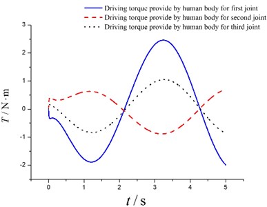
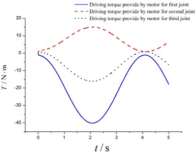
Fig. 10The angular deviations
5. Experimental verification
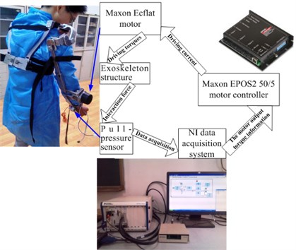
Incontestably, the most joints of human extremity exoskeleton need to be driven by motors in order to achieve best power support effect. However, if the purpose is to verify the rationality and feasibility of the interaction force control scheme and the simulation results, the simple and convenient upper extremity exoskeleton experimental scheme (as shown in Fig. 11) can achieve the same results.
As shown in Fig. 11, only the second joint (elbow joint) of the upper extremity exoskeleton is driven by motor, and all other joints are driven by human body. Besides, one pull-pressure sensor is installed on the forearm of the upper extremity exoskeleton to detect the interaction force information.
Firstly, the interaction force information detected by the pull-pressure sensor is transferred to the NI (National instruments) data acquisition system. And then, the motor control signal will be obtained by the program of the NI data acquisition system. After that, the motor control signal is transferred to the Maxon motor controller. At last, the motor of upper extremity exoskeleton will be controlled by the motor controller to obey the movement of human body.
Obviously, it is difficult to realize the same experimental process with the simulation. However, the most similar process was conducted as better as we can. When the experiment was conducted, a payload about 15 kg was bundled to the end of the exoskeleton’s forearm. And the movement process just like dumbbell exercise was implemented by the pilot. The amplitude of the movement process was about 25°, and the frequency was about 0.5 Hz.
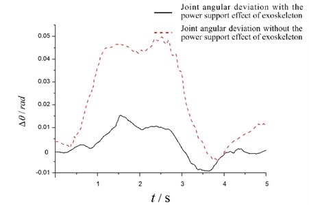
Although the driving torque of human body and the angular deviation was not convenient to be directly measured, the interaction force was fortunately already measured out by the pull-pressure sensor. So the angular deviation of the second joint (elbow joint) can be calculated according to the man-machine interaction model. Besides, the angular deviation without the power support effect of exoskeleton was also calculated by shutting down the motor when conducting the experiment. The experimental second joint angular deviations are shown in Fig. 12.
Fig. 11Upper extremity exoskeleton experimental scheme
It can be seen from Fig. 12 that the largest second joint angular deviations with the power support effect of exoskeleton is about 0.014 rad, and it is quite similar with the simulation result (0.012 rad). Besides, by comparing the two curves of Fig. 12, it is obvious that the largest interaction force without the power support effect of exoskeleton is much larger than that with the power support effect of exoskeleton. So on the other hand, the comparative result can also prove that the interaction force control scheme can help human body bear heavy payload. And from the experience of the pilot, the movement process was easily implemented with the power support effect of exoskeleton. In contrast, the movement process will become much harder for the pilot if the power support effect of exoskeleton was removed.
Fig. 12Experimental second joint angular deviations
6. Conclusion
To seek a rational and feasible control scheme for human extremity exoskeleton: Firstly, the interaction force control scheme was proposed. Secondly, the human extremity exoskeleton model was simplified. Then the electromechanical system model was established. And then, the simulation model was established and the simulation was carried out. At last, the rationality and feasibility of the interaction force control scheme for human extremity exoskeleton was verified based on the simulation result. In addition, the upper extremity exoskeleton experiment was conducted, and it arrived at the same conclusions with the simulation study.
However, the PID controller parameters are just suitable for the simulated and experiment condition, they are not very suitable for every movement speed of human body. So, the future work is to seek more superior control algorithm to optimize the PID controller, and the target is to improve the adaptability and anti-interference performance of the system.
References
-
Zhang Jiafan, Chen Ying, Yang Canjun Man-Machine Intelligent Systems of Flexible Exoskeletons. Science Press, 2011, p. 5-6.
-
Yang Zhiyong, Gu Wenjing, Zhang Jing, Gui Lihua Force Control Theory and Method of Soldier Load Carrying Exoskeleton Suit. National Defense Industry Press, 2013, p. 1-5
-
Zoss A., Kazerooni, Kazerooni H. On the mechanical design of the Berkeley lower extremity exoskeleton (BLEEX). Proceedings of IEEE Intelligent Robots and Systems, Edmonton, Canada, 2005, p. 3132-3139.
-
Zoss A., Kazerooni, Kazerooni H., Andrew Chu On the biomechanical design of the Berkeley lower extremity exoskeleton (BLEEX). IEEE/ASME Transactions on Mechatronics, Vol. 11, Issue 2, 2006, p. 128-138.
-
Kazerooni H., Jean-Louis Racine, Lihua Huang, Ryan Steger On the control of Berkeley lower extremity exoskeleton (BLEEX). Proceedings of IEEE International Conference on Robotics and Automation, Barcelona, Spain, 2005, p. 4364-4371.
-
Tomoyoshi Kawabata, Hozumi Satoh Working posture control of robot suit HAL for reducing structural stress. IEEE International Conference on Robotics and Biomimetics, Guilin, China, 2009.
-
Low K. H., Xiaopeng Liu, Haoyong Yu Development of NTU wearable exoskeleton system for assistive technologies. IEEE International Conference on Mechatronics and Automation Niagara Falls, Canada, 2005, p. 1099-1106.
-
Conor Jame Walsh, Ken Endo, et al. A quasi-passive leg exoskeleton for load-carrying augmentation. International Journal of Humanoid Robotics, Vol. 4, Issue 3, 2007, p. 487-506.
-
Ma Meng The Freedom of Walking. Business Review of the 21st Century. 2010, p. 1-7.
-
Kong Kyoungchul, Masayoshi Tomizuka Control of exoskeletons inspired by fictitious gain in human model. IEEE/ASME Transaction on Mechatronics, Vol. 14, Issue 3, 2009, p. 358-370.
-
Fu Chenglong Section Mapping Stability Criterion and Application of the Plane Biped Robot. Ph.D. Thesis, Tsinghua University, Beijing, 2006.
-
Li Zhengyi, Cao Huimin Robot impedance control method adapting to unknown or changing environment stiffness and damping parameters. China Mechanical Engineering, 2014, p. 1581-1585.
-
Li Yang, Guan Xiaorong, Xu Cheng Dynamics simulation of lower extremity exoskeleton based on human gait. Journal of Nanjing University of Science and Technology, 2015, p. 353-357.
-
Li Yang, Guan Xiaorong, Tong Yifei, Xu Cheng Design and simulation study of the translational-knee lower extremity exoskeleton. Mechanika. Vol. 21, Issue 3, 2015, p. 207-213.
-
Amit G., Michal M. R. In vivo biomechanical behavior of the human heel pad during the stance phase of gait. Journal of Biomechanics, 2001, p. 1661-1665.
About this article

This study was supported in part by the key Projects of Base Scientific Research Plan of China National Defense (Grant Number B10****2012).
