Abstract
The effect of temperature on the performance of a giant magnetostrictive ultrasonic transducer (GMUT) was investigated by measuring variations in the resonance frequency and mechanical quality factor of the GMUT at different temperatures. The equivalent circuit model of the GMUT was presented and the total electrical impedance equation was obtained. Curves of the impedance circle were obtained at different temperatures to determine the resonance frequency and mechanical quality factor. To verify the impedance-based results and obtain precise values of the resonance frequency and effective frequency bandwidth, the amplitude-frequency response within the same temperature range was examined experimentally. These results were consistent with those of the impedance analysis, which demonstrates the validity of the equivalent circuit model. Moreover, the resonance frequency and effective bandwidth of the GMUT were found to decrease with increasing temperature, which means that the vibration amplitude is more sensitive to variation in the resonance frequency at high temperature owing, for example, to static or dynamic system loading, changes in the material properties, or drive-signal variability. Accordingly, the temperature in the GMUT should be precisely controlled to improve the stability of vibration.
1. Introduction
Rotary ultrasonic machining (RUM) is used in the machining of hard and brittle materials [1-4]. To improve the machining efficiency and surface integrity of brittle materials, high-power RUM systems with large vibration amplitudes are required. Two main types of energy-conversion material, piezoceramics and giant magnetostrictive materials (GMMs), are widely used in RUM systems. GMMs have giant magnetostriction (over 1000 ppm), high energy density, and fast response speeds, which make them well-suited as transducer materials for high-power RUM. At present, GMMs are widely used as energy-conversion materials in areas such as sonochemistry, industrial processing, and medicine [5, 6]. However, the temperature rise in GMMs caused by hysteresis and eddy current losses seriously affects the stability of vibration (with respect to the amplitude) and the machining accuracy. Thus, understanding and compensating for the temperature dependence of the vibration amplitude of GMMs is critical for the continuous application of giant magnetostrictive ultrasonic transducers (GMUTs) in high-power RUM [7-9].
Much attention has been focused on the properties of GMMs and the temperature response of magnetoelastic sensors and actuators. To investigate the effects of temperature on the properties of GMMs, Clark and Crowder experimentally examined the high-temperature magnetomechanical transfer efficiencies and saturation magnetostriction of GMMs [10]. Grimes and co-workers studied the resonant-frequency-temperature response of a magnetoelastic sensor at various bias magnetic field intensities. It was subsequently shown that the temperature response of the magnetoelastic sensor could be made negative, positive, or zero by varying the DC biasing field [11, 12]. Jin et al. proposed a 3D nonlinear dynamic model to describe the magneto-thermoelastic coupling behavior of actuators [13]. Woollett established the lumped-parameter equivalent circuit of transducers and an effective coupling factor was proposed to quickly reveal the relationship between the mechanical vibration and the electrical signals [14]. However, there are few reports of the effect of temperature on the vibration amplitude of GMUTs.
In this work, a GMUT was designed and the stability of the vibration amplitude was examined at various temperatures. We first present the equivalent circuit model of the GMUT and the impedance circle equation at different temperatures. Based on the magnetostrictive mechanism, temperature-dependent variations in the resonance frequency are presented. By testing the GMUT impedance, curves of the impedance circle in the temperature range of 26.4-41.4 °C were obtained and the resonance frequency, half-power bandwidth and mechanical quality factor were determined. Moreover, the amplitude–frequency response within the same temperature range was examined experimentally to obtain the precise resonance frequency and effective frequency bandwidth to verify the results based on the impedance measurements.
2. Design and modeling of the GMUT
2.1. Structure
The structure of the GMUT, shown in Fig. 1, can be divided into two components: a giant magnetostrictive transducer and a horn. The parameters of the GMUT used are listed in Table 1. The transducer consists of a GMM (i.e., Terfenol-D), coil skeleton, coil, prestress block, case, flux sleeve, output rod, and permanent magnets. To increase the ultrasonic amplitude, a horn with a diameter ratio of 2:1 was connected to the transducer. To suppress the eddy current effect, a laminated GMM was used with a lamination thickness of 1 mm. A suitable magnetic field is provided by the permanent magnet such that the transducer can operate at maximum magnetostriction-current sensitivity and with a large vibration amplitude. The driving magnetic field is provided by the coil, which is wrapped around the GMM.
Fig. 1Schematic of the GMUT
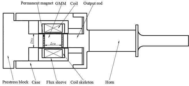
Table 1Parameters of the GMUT
Item | Value | |
GMM | Material | Tb0.3Dy0.7Fe1.92 |
Length (mm) | 16 | |
Diameter (mm) | 13 | |
Lamination thickness (mm) | 1 | |
Coil | Number of turns | 180 |
Diameter (mm) | 0.6 | |
Horn | Material | 45# |
Length (mm) | 129 | |
Diameter of the back end (mm) | 20 | |
Diameter of the front end (mm) | 10 | |
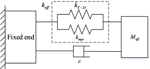
Owing to the single-degree-of-freedom vibration characteristic of GMUTs, a mass spring damping system is employed to describe the vibration, as shown in Fig. 2 [15]. Because the acoustic impedance of the pre-stress block is much larger than that of the output rod, a vibrating terminal is used as a fixed end. Thus, the resonance frequency of the GMUT can be expressed in Eqs. (1)-(3):
where and are the effective stiffness and effective mass of the GMUT, is the Terfenol-D core stiffness, is the stiffness owing to other mechanisms, is the Young’s modulus of the Terfenol-D core, is the diameter, and is the length.
Fig. 2Equivalent mechanical model of GMUT
2.2. Equivalent circuit of GMUT
Because the electric, magnetic, mechanical, and thermal properties are fully coupled in the GMUT system, the energy transduction process in GMUTs is rather complicated. The energy transduction process in GMUTs can be considered a black box with the system parameters estimated. Thus, transduction coefficients are introduced to describe the electromechanical coupling. The coupled electromechanical equivalent circuit of the GMUT is shown in Fig. 3(a). The electrical system and mechanical equivalent circuit are linked by the transduction coefficients and [15, 16].
Fig. 3Equivalent circuit of the GMUT
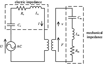
a) Electromechanical coupling equivalent circuit
b) Electrical equivalent circuit
As shown in Eq. (4), the system can be described by two coupled linear equations:
where is the excitation voltage; is the excitation current; is the drive force; is the velocity; is equivalent mechanical impedance; is the blocked electrical impedance.
The mechanical impedance of the GMUT is expressed as:
According to the equivalent mechanical model of the GMUT shown in Fig. 2, the mechanical capacitance, inductance and resistance can be calculated from the stiffness, mass and damping respectively as follows:
where is the equivalent mechanical resistance, is the inductance, is the capacitance, and is the damping coefficient.
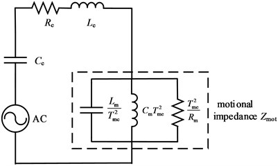
Through equivalent transformation, the total electrical equivalent circuit was obtained, as shown in Fig. 3(b). Motional impedance is one part of the total electrical impedance and arises from transduction of mechanical motion. The total electrical impedance, , the blocked electrical impedance, , and the motional impedance, , are given as follows:
where is the resistance, and is the inductance. For reciprocal processes, the two transduction coefficients, and , have the following relationship:
Substituting Eqs. (5), (8), and (9) into Eq. (7), the total electrical impedance can be expressed as:
The complex motional impedance needs to be considered to calculate the resonant frequency; hence:
where:
For the mechanical resonance of the system, the reactive component of the motional impedance is zero. Thus, the resonance frequency can be calculated as follows:
According to Eq. (13) and the circuit equivalent transformation, the motional impedance can be regarded as a circle with its center at and a radius of , as described below [17]:
The total electrical impedance can be obtained through measurement of the GMUT impedance with an impedance analyzer; however, the motional impedance cannot be measured separately. Moreover, according to Eq. (8), the blocked electrical impedance is a linear function of frequency; thus, the reactive component of the total electrical impedance does not equal zero near the resonance frequency. Therefore, it is not possible to determine the resonance frequency and mechanical quality factor precisely based on the total electrical impedance, particularly for an ultrasonic vibration system. In addition, the large inductive impedance limits the ultrasonic power. To improve the accuracy of the calculated resonance frequency, mechanical quality factor and ultrasonic power, a suitable capacitance should be installed into the GMUT to reduce the reactive component of the blocked electrical impedance near the resonance frequency. The compensation capacitance, , can be determined from the resonance frequency and electrical inductance using Eq. (16). The total electrical impedance is then determined from Eq. (17) and the blocked electrical impedance can be expressed as Eq. (18):
The mechanical quality factor of a GMUT is generally large; thus, a change in frequency in the mobility loop of the total electrical impedance is quite small [5]. Therefore, the dependence of the blocked electrical impedance on frequency in the mobility loop can be ignored, and the blocked electrical impedance at the resonance frequency is taken as the equivalent electrical impedance at all points in the mobility loop. Accordingly, the blocked electrical impedance can be modified as follows:
The total electrical impedance of the GMUT near the resonance frequency can be regarded as a circle with a center at and a radius of , which can be expressed as:
According to Eq. (20), the reactive component of the total electrical impedance, , at the resonance frequency is zero; thus, the cross point of the mobility loop and the real axis is the resonance frequency. Half-power frequencies can be obtained at ±90° from the resonance frequency in the mobility loop. The mechanical quality factor can then be calculated as follows:
where is the resonance frequency, and and are the half-power frequencies.
3. Effect of temperature rise on the vibration amplitude of the GMUT
3.1. Effect of temperature rise on the Young’s modulus of the GMM
The parameters in the equivalent circuit of the GMUT are influenced by the operating conditions, including the static or dynamic load, pre-stress, and temperature. The temperature rise in the GMUT, caused by eddy current and hysteresis losses of the GMM, affects the resonance frequency and mechanical quality factor. As a result, the stability of the vibration amplitude is influenced by the temperature of the GMUT.
Young’s modulus is defined in Eq. (22). Owing to magneto-elastic coupling, the strain in the GMM is composed of elastic strain, , and magnetostrictive strain, , [18, 19], as expressed in Eq. (23):
According to the mechanism of magnetostriction, the magnetization of GMM is composed of domain-wall motion and domain rotation. Previous reports have shown that movement of the magnetization vector in the direction of the applied field is fundamental to magnetostriction [16]. With increasing temperature, the internal energy of the GMM increases and the energy potential well of the easy axis of magnetization decreases [20]. Thus, a weaker magnetic field is required to overcome the anisotropy energy and the magnetization vector of the domain can move to another easy axis of magnetization (i.e., one that is closer to the direction of the applied field). Larger magnetostrictive strain can be achieved in a uniform external applied field. This means that the magnetostrictive strain increases as the temperature increases in the GMM. Therefore, according to Eqs. (22) and (23), the Young’s modulus, , of the GMM decreases with increasing temperature, which results in a lower resonance frequency. However, the electric, magnetic, mechanical, and thermal properties are fully coupled in the GMUT system. The relationship between the Young’s modulus and temperature is nonlinear because of magnetostriction. To investigate the effect of temperature quantitatively, the equivalent circuit can therefore be employed.
A similar conclusion to that described above can be drawn from the equivalent circuit of the GMUT. According to Eqs. (3) and (6), a relationship between the mechanical equivalent capacitance and Young’s modulus can be established, as expressed in Eq. (24); specifically, the mechanical equivalent capacitance increases with temperature and can be calculated from the Young’s modulus of the GMM, . The resonance frequency can then be obtained using Eq. (25), according to which the resonance frequency decreases with increasing temperature. The frequency of the cross point of the mobility loop and real axis reduces according to Eqs. (13) and (20). This means that the impedance circle equation is appropriate for GMUTs at different temperatures, and can be used to reveal the effect of temperature on the resonance frequency and mechanical quality:
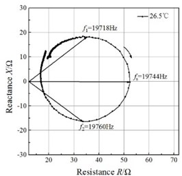
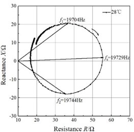
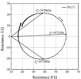
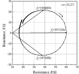
Fig. 4Impedance circles of the GMUT at different temperatures
a)
b)
c)
d)
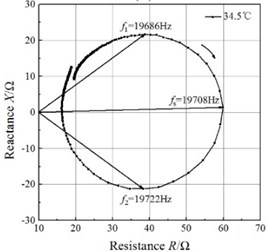
e)
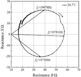
f)
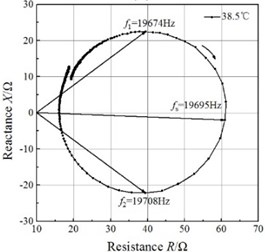
g)
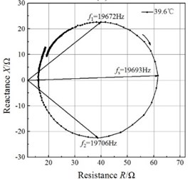
h)
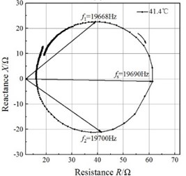
i)
3.2. Properties of ultrasonic vibration obtained from impedance circles
According to Eq. (16), the compensation capacitance, , is determined by the resonance frequency and electrical inductance. The electrical inductance was measured with a digital multimeter at ambient temperature. Because the electrical inductance is independent of temperature, a compensation capacitance of 140 nF can be calculated using Eq. (16). The compensation capacitance varies by less than 3 nF when the resonance frequency increases from 19400 to 19600 Hz; thus, variation in compensation capacitance can be neglected. Thus, the compensation capacitance at ambient temperature was used for the measurement of the total electrical impedance at all temperatures.
An impedance analyzer (PV80A, Bandera, China) was employed to measure the total electrical impedance. The mobility loops of the electrical impedance of the GMUT are presented in Fig. 4. The mobility loop at each temperature approximates a circle, which validates the impedance circle equation. The mobility loops enable the determination of the resonance frequency and half-power frequencies, and the mechanical quality factor can be calculated with Eq. (21). The half-power bandwidths of the GMUT are lower than 50 Hz at all temperatures, which allows the asymptote of the blocked electrical impedance in the mobility loop to be used.
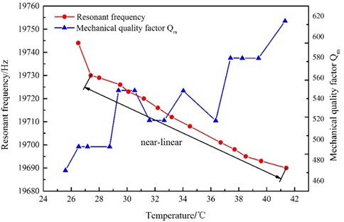
The changes in resonance frequency and mechanical quality factor with temperature are shown in Fig. 5. The resonance frequency decreases monotonously with increasing temperature, and the relationship between the resonance frequency and temperature is almost linear in the temperature range of 27-41.4 °C. These results are in good agreement with the results of the theoretical analysis. However, the mechanical quality factor, despite increasing on the whole over this temperature range, does not change linearly. A lower mechanical quality means the transducer remains effective in spite of variation in the resonance frequency caused by static or dynamic system loading, changes in the material properties, or drive-signal variability. Therefore, at ambient temperature, the GMUT possesses a wider effective bandwidth, resulting in significantly greater stability.
Fig. 5Resonance frequency and mechanical quality factor as functions of temperature
4. Validation tests
4.1. Experimental setup
To verify the effects of temperature on the resonance frequency and mechanical quality factor, the amplitude-frequency responses of the GMUT were investigated at temperatures of 27, 30, and 35 °C. The experimental system is shown in Fig. 6. A high-speed bipolar power supply (BP4610, NF, Japan) was used to generate the excitation signals. Different voltages were used to adjust the temperature, which was measured using a temperature sensor and was constant throughout each measurement. The electrical signal was monitored using an oscilloscope (MDO3041, Tektronix, Ohio) and a laser displacement sensor (LK-G5000, Keyence, Japan) was employed to measure peak-to-peak displacement as the frequency was adjusted.
4.2. Results and discussion
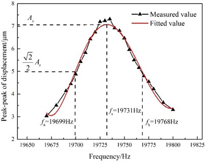
The peak-to-peak displacements of the transducer are shown in Figs. 7-9 as functions of frequency for constant temperatures of 27, 30, and 35 °C, respectively. It can be seen that the resonant frequencies occur at the points of maximum peak-to-peak displacement. To quantify the stability of the vibration amplitude at different temperatures, the frequency bandwidth of the maximum peak-to-peak displacement is defined as the effective bandwidth. Because of the high mechanical quality factor of the GMUT, the effective bandwidth is narrow and the peak-to-peak displacement is sensitive to variations in the frequency, especially near the resonance frequency. In addition, the peak-to-peak displacement is also influenced by the temperature of the GMUT. As shown in Figs. 7 and 8, the effective bandwidth of the GMUT at 27 °C is wider than that at 30 °C. This means that the displacement of the GMUT at 30 °C is more sensitive to the frequency. However, the effective bandwidths of the GMUT at 30 and 35 °C are similar, which can be explained by the similar mechanical quality factors at these temperatures.
Fig. 6Experimental setup
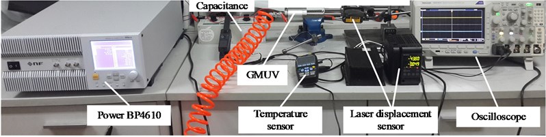
Fig. 7Peak-to-peak displacement as a function of GMUT frequency (temperature: 27 °C; excitation voltage: 12 Vp-p)
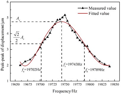
Fig. 8Peak-to-peak displacement as a function of GMUT frequency (temperature: 30 °C; excitation voltage: 15 Vp-p)
The resonance frequency and mechanical quality factor at a given temperature can be obtained through interpolation of the data shown in Fig. 5. To further validate the equivalent circuit model of the GMUT, the results of the impedance analysis and validation test at 27, 30, and 35 °C are compared in Table 2. The good agreement between the results of the two methods validates the equivalent circuit model.
The resonance frequency decreased from 19743 to 19721 Hz with increasing temperature, because of the lower Young’s modulus of the GMM; this indicates that a temperature rise in the GMUT lowers the stability of the vibration amplitude at constant driving power. Because the mechanical quality factor varies considerably from 27 to 30 °C, the effective bandwidth is broader at the lower temperature. The mechanical quality factor does not vary appreciably between 30 and 35 °C; thus, the effective bandwidths are similar within this range. These results indicate that high mechanical quality factor is corresponding to smaller effective bandwidth. In addition, the mechanical quality factor increases on the whole over the whole temperature range, as shown in Fig. 5, so the effective bandwidth reduces with increasing temperature. Therefore, the vibration amplitude of the GMUT at high temperature is more sensitive to variation in the resonance frequency, which result, for example, from static or dynamic system loading, changes in the material properties, drive signal variability. It is therefore evident that the temperature of the GMUT should be controlled precisely to improve the stability of the vibration amplitude.
Fig. 9Peak-to-peak displacement as a function of GMUT frequency (temperature: 35 °C; excitation voltage: 18 Vp-p)
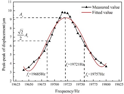
Table 2Comparison of the results of the impedance analysis and the experimental results
Temperature (°C) | Impedance analysis results | Validation test results | ||
Resonance frequency (Hz) | Mechanical quality factor | Resonance frequency (Hz) | Effective bandwidth (Hz) | |
27 | 19736 | 482.96 | 19743 | 87 |
30 | 19724 | 547.86 | 19731 | 69 |
35 | 19707 | 540.85 | 19721 | 72 |
5. Conclusions
In this work, the equivalent circuit model of a GMUT was presented and the total electrical impedance equation was derived to investigate the influence of temperature on the stability of vibration. The following conclusions are drawn:
1) The resonance frequency and mechanical quality factor can be accurately calculated based on the equivalent circuit model of the GMUT over a range of temperatures.
2) The resonance frequency decreases and the mechanical quality factor increases (albeit non-linearly) with increasing temperature. Moreover, the stability of the vibration amplitude at high temperature is more sensitive to changes in frequency. Therefore, the excitation frequency needs to be adjusted so that the GMUT can operate at maximum amplitude, and the temperature should be controlled precisely to improve the stability of the vibration amplitude.
3) The effect of temperature on the stability of the GMUT can be explained in terms of variations in the Young’s modulus of the GMM. At higher temperature, a lower magnetic field is required to overcome the anisotropy energy and a larger magnetostrictive strain is achieved under a constant external applied field. Thus, the Young’s modulus of the GMM decreases, resulting in a lower resonance frequency and effective bandwidth.
References
-
Wan Y., Lin B., Wang S. L., Cao X. Y. Study on the system matching of ultrasonic vibration assisted grinding for hard and brittle materials processing. International Journal of Machine Tools and Manufacture, Vol. 77, 2014, p. 66-73.
-
Bertsche E., Ehmann K., Malukhin K. An analytical model of rotary ultrasonic milling. Robotics and Computer-Integrated Manufacturing, Vol. 30, 2013, p. 344-350.
-
Voronina S., Babitsky V., Meadows A. Modelling of autoresonant control of ultrasonic transducer for machining applications. Proceedings of the Institution of Mechanical Engineers, Part C: Journal of Mechanical Engineering Science, Vol. 222, 2008, p. 1957-1974.
-
Zhang S. J., To S., Wang S. J., Zhu Z. W. A review of surface roughness generation in ultra-precision machining. International Journal of Machine Tools and Manufacture, Vol. 91, 2015, p. 76-95.
-
Liu H., Wang S., Zhang Y., Wang W. G. Study on the giant magnetostrictive vibration-power generation method for battery-less tire pressure monitoring system. Proceedings of the Institution of Mechanical Engineers, Part C: Journal of Mechanical Engineering Science, Vol. 229, 2015, p. 1639-1651.
-
Weisensel G. N., Hansen T. T., Hrbek W. D. High-power ultrasonic TERFENOL-D transducers enable commercial applications. 5th Annual International Symposium on Smart Structures and Materials, International Society for Optics and Photonics, 1998.
-
Jiles D. C., Thoelke J. B., Devine M. K. Numerical determination of hysteresis parameters for the modeling of magnetic properties using the theory of ferromagnetic hysteresis. IEEE Transactions on Magnetics, Vol. 28, 1992, p. 27-35.
-
Calkins F. T., Smith R. C., Flatau A. B. Energy-based hysteresis model for magnetostrictive transducers. IEEE Transactions on Magnetics, Vol. 36, 2000, p. 429-439.
-
Zhu Y., Ji L. Theoretical and experimental investigations of the temperature and thermal deformation of a giant magnetostrictive actuator. Sensors and Actuators A, Vol. 218, 2014, p. 167-178.
-
Clark A. E., Crowder D. N. High temperature magnetostriction of TbFe2 and Tb27Dy73Fe2. IEEE Transactions on Magnetics, Vol. 21, 1985, p. 1945-1947.
-
Jain M. K., Schmidt S., Ong K. G., Mungle C., Grimes C. A. Magnetoacoustic remote query temperature and humidity sensors. Smart Materials and Structures, Vol. 9, 2000, p. 502-510.
-
Ong K. G., Mungle C. S., Grimes C. A. Control of a magnetoelastic sensor temperature response by magnetic field Tuning. IEEE Transactions on Magnetics, Vol. 39, 2003, p. 3319-3321.
-
Jin K., Kou Y., Zheng X. J. The resonance frequency shift characteristic of Terfenol-D rods for magnetostrictive actuators. Smart Materials and Structures, Vol. 21, 2012, p. 1-7.
-
Woollett R. S. Effective coupling factor of single degree of freedom transducers. Journal of the Acoustical Society of America, Vol. 40, 1966, p. 1112-1123.
-
Wakiwaka H., Lio M., Nagumo M., Yamada H. Impedance analysis of acoustic vibration element using giant magnetorestrictive material. IEEE Transactions on Magnetics, Vol. 28, 1992, p. 2208-2210.
-
Calkins F. T. Design, Analysis, and Modeling of Giant Magnetostrictuve Transducers. Ph.D. Dissertation, Aerospace Engineering – Iowa State University, 1994.
-
Hall D. L. Dynamics and Vibrations of Magnetostrictive Transducers. Ph.D. Dissertation, Aerospace Engineering – Iowa State University, 1994.
-
Garcỉa-Arribas A., Cos D. De., Gutiérrez J., Barandiarán J. M. Selectable temperature sensitivity of the magnetoelastic resonance. Sensors and Actuators A, Vol. 106, 2003, p. 111-116.
-
Mungle C., C. Grimes A., Dreschel W. R. Magnetic field tuning of the frequency-temperature response of a magnetoelastic sensor. Sensors and Actuators A: Physical, Vol. 101, 2002, p. 143-149.
-
Jiles D. C., Atherton D. L. Theory of ferromagnetic hysteresis. Journal of Applied Physics, Vol. 55, 1984, p. 2115-2120.
Cited by
About this article

We gratefully acknowledge the financial support for this research from the National Nature Science Foundation of China (Grant No. 51475260), the Beijing Natural Science Foundation (Grant No. 3141001), the Beijing Science and Technology Program (Grant No. D131100002713003), and the State Key Lab of Tribology of China (Grant No. SKLT2013B03).
