Abstract
The failure occurred frequently when rubbing, especially when the rotating machinery worked in abnormal conditions. The research of friction coefficient on rubbing behavior was not much. The model of rubbing rotor system was established. The rubbing characteristics of the different friction coefficient were compared and analyzed. The results showed the friction coefficient had no effect on motion of period 1, period 2 and period-doubling bifurcation, when rotating speed was low. With the increase of the friction coefficient, the chaotic motion transformed into quasi-periodic, and period N motion when rotating speed was in 760-820 rad/s. The chaotic motion disappeared when rotating speed was in 1260-1400 rad/s, and the zone of quasi-periodic motion was expanding.
1. Introduction
The failure occurred frequently when rubbing, especially when the rotating machinery worked in abnormal conditions. A large number of researches were conducted in the world. Enrich [1] studied the rotor system with gap characteristic and nonlinear contact. The sub-harmonic, super-harmonic and chaotic behavior excited by unbalance was obtained. Yamane [2] studied the rubbing behavior between protection ring and rotor passing critical speed, and analyzed simulation results of collision model and contact model. Based on piecewise linear stiffness, viscous damping and dry friction, a rubbing model was built, Goldman [3] simulated the super harmonic, sub-harmonic chaotic behavior of the rotor system. Choy [4] studied transient response of rubbing rotor system; the results showed unbalance and friction coefficient can induce anti-precession or rotor. Zhang [5], Jiang [6] studied the stability of synchronous full annular rub motion. Chu [7] studied nonlinear dynamic behavior of rub-impact using a Jeffcott rotor system. Yuan [8] studied coupling rubbing behavior between axial and radial of rotor.
However, the research of friction coefficient on rubbing behavior was not much. The model of rubbing rotor system was established. The rubbing characteristics of the different friction coefficient were compared and analyzed, which provided engineering experience for rubbing research.
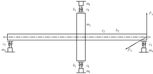
Fig. 1Dynamic model of rubbing rotor system
2. Rubbing dynamic model of oil bearing rotor system
Figure 1 shows the dynamic model of rubbing rotor system. The physical parameters of system are shown in Table 1.
Table 1The physical parameters
Parameters | Parameters | ||
Diameter of oil bearing | Damping of wheel disc | ||
Active length of oil bearing | Eccentric | ||
Bearing clearance | Stiffness of shaft | ||
Dynamicviscosity | Stiffness of stator | ||
Equivalent mass of bearing | Damping of stator | ||
Damping of bearing | Gap of rotor and stator | ||
Equivalent mass of wheel disc | Nonlinear oil film force | , |
2.1. Rub-impact force
The piecewise smooth model was used in rub-impact force model [9]. Assuming radial deformation of stator was linear, and rubbing conformed to the coulomb friction law. So the rubbing force were as shown in equations (1):
where, the initial position of the stator center was . The stator center was moved to after the first rubbing, which had coordinate values , . was the gap between rotor and stator, was static relative displacement, and was the friction coefficient.
2.2. Model of oil film force
Capone short bearing model was used and its dimensionless nonlinear oil film force was shown in reference [9]. The equations were as follows:
where:
was correction factor of Sommerfeld, was half of the rotor weight.
2.3. Dynamic equations of rubbing rotor system
The dynamic equations were as follows:
where, was rotational angular velocity of rotor, was bearing clearance, , was rubbing force, , was oil film force, was dimensionless time, was acceleration of gravity.
3. Numerical simulation
The system parameters were shown in Table 2. In order to obtain steady-state dynamic response, the first 800 periods of 1000 periods were abandoned.
Table 2Values of physical parameters
Parameters | Values | Parameters | Values |
66 mm | 660 N·s/m | ||
22 mm | 0.132 mm | ||
0.242 mm | 9.361×10⁶ N/m | ||
0.0198 Pa·s | 2.2×10⁷ N/m | ||
3.135 kg | 660 N·s/m | ||
330 N·s/m | 0.242 mm | ||
13.86 kg | 0~0.4 |
3.1. Dynamic response without friction
Rubbing bifurcation with no friction when the speed increasing was shown in Figure 2, and motion behavior was shown in Table 3. With changing of the rotating speed, the rotor system response had periodic motion, quasi-periodic motion and chaotic motions. The rotor system had period 1motion when the rotating speed was low. As the speed increases, the rotor system was losing stability because of nonlinear oil film force and unbalance. A period-doubling bifurcation occurred when the rotating speed was 400 rad/s. The rotor system went into chaotic motion by period-doubling bifurcation, and was out chaotic motion region by inverse bifurcation when rotating speed was 1120 rad/s. The rotor system went into transitory chaotic motion again when rotating speed was 1310 rad/s, and lasted to 1330 rad/s. The rotor system had period and quasi-periodic motion in most of the remaining time.
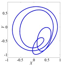
Fig. 3 shows vibration of the rotor when it rotates at several speeds. The axis orbit and Poincare map when speed was 560 rad/s were shown in Fig. 3(a) and Fig. 3(b). Its Poincare map had four isolated points in Fig. 3(b), which indicated P-4 motion. The axis orbit and Poincare map when speed was 860 rad/s were shown in Fig. 3(c) and Fig. 3(d). It was found that the axis orbit appeared as chaotic trajectory. The Poincare map had self-similar structure, which was a typical chaotic attractor. The axis orbit and Poincare map when speed was 1260 rad/s were shown in Fig. 3(e) and Fig. 3(f). Its Poincare map was closed circle, which showed quasi periodic motion.
Fig. 2Bifurcation of wheel disk Y2 (f=0)
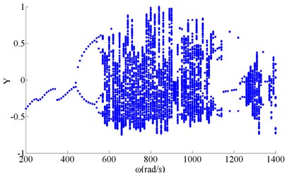
Table 3Responses without friction
Rotating speed (rad/s) | Response | Rotating speed (rad/s) | Response |
200-430 | P-1 | 1220 | P-2 |
440-530 | P-2 | 1230-1250 | P-3 |
540-570 | period-doubling bifurcation | 1260-1300 | quasi-period |
580-1110 | chaotic | 1310-1330 | chaotic |
1120-1130 | P-4 | 1340-1360 | P-1 |
1140-1210 | P-1 | 1370-1400 | quasi-period |
Fig. 3Vibration characteristics of wheel disk
a) Axis orbit, 560 rad/s
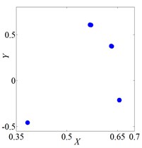
b) Poincare map, 560 rad/s
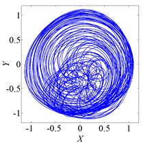
c) Axis orbit, 860 rad/s
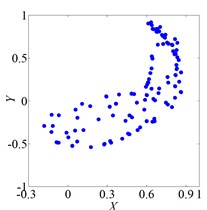
d) Poincare map, 860 rad/s
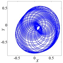
e) Axis orbit, 860 rad/s
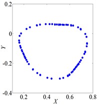
f) Poincare map, 860 rad/s
3.2. Influence of friction coefficient on dynamic response
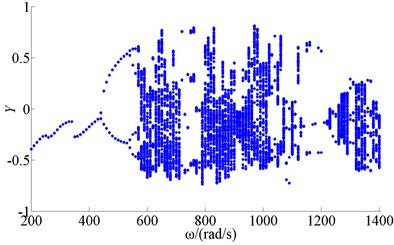
Figure 4 showed bifurcation of wheel disk Y2 when friction coefficient was 0.1. Figure 5 showed bifurcation of wheel disk Y2 when friction coefficient was 0.2. Figure 6 showed bifurcation of wheel disk Y2 when friction coefficient was 0.3. The results showed the friction coefficient had no effect on motion of period 1, period 2 and period-doubling bifurcation, when rotating speed was low. With the increase of the friction coefficient, the chaotic motion transformed into quasi-periodic, and period N motion when rotating speed was in 760-820 rad/s. The chaotic motion disappeared when rotating speed was in 1260-1400 rad/s, and the zone of quasi-periodic motion was expanding.
Fig. 4Bifurcation of wheel disk Y2 (f= 0.1)
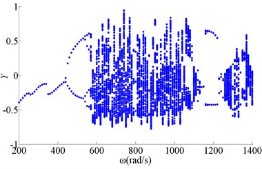
Fig. 5Bifurcation of wheel disk Y2 (f= 0.2)
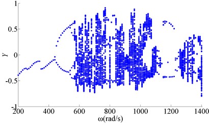
Fig. 6Bifurcation of wheel disk Y2 (f= 0.3)
4. Conclusions
1. The model of rubbing rotor system was established. With changing of the rotating speed, the rotor system response had periodic motion, quasi-periodic motion and chaotic motions.
2. The friction coefficient had no effect on motion of period 1, period 2 and period-doubling bifurcation, when rotating speed was low.
3. With the increase of the friction coefficient, the chaotic motion transformed into quasi-periodic, and period N motion when rotating speed was in 760-820 rad/s. The chaotic motion disappeared when rotating speed was in 1260-1400 rad/s, and the zone of quasi-periodic motion was expanding.
References
-
Ehrich F. High order sub harmonic response of high speed rotors in bearing clearance. ASME Journal of Vibration, Acoustics, Stress and Reliability in Design, Vol. 110, 1988, p. 9-16.
-
Yanabe S., et al. Rotor vibration due to collision with annular guard during passage through critic speed. Journal of Vibration and Acoustics, Vol. 120, 1998, p. 544-550.
-
Goldman P., Muszynska A. Dynamic effects in mechanical structures with gaps and impacting: order and chaos. ASME Journal of Vibration and Acoustics, Vol. 116, Issue 4, 1994, p. 541-547.
-
Choy F. K., Padovan J. Rub interaction of flexible casing rotor systems. ASME Journal of Engineering for Gas Turbine and Power, Vol. 111, 1989, p. 652-658.
-
Zhang G. F., Xu W. N., Xu B., et al. Analytical study of nonlinear synchronous full annular rub motion of flexible rotor-stator system and its dynamic stability. Nonlinear Dynamics, Vol. 57, Issue 4, 2009, p. 579-592.
-
Jiang J., Ulbrich H. Stability analysis of sliding whirl in a nonlinear Jeffcott rotor with cross-coupling stiffness coefficients. Nonlinear Dynamics, Vol. 24, Issue 3, 2001, p. 269-283.
-
Chu F. L., Zhang Z. S. Bifurcation and chaos in a rub-impact Jeffcott rotor system. Journal of Sound and Vibration, Vol. 210, Issue 1, 1998, p. 1-18.
-
Yuan Z. W., Chu F. L., Hao R. J. Simulation of rotor’s axial rub-impact in full degrees of freedom. Mechanism and Machine Theory, Vol. 42, Issue 7, 2007, p. 763-775.
-
Li Chaofeng, Li Xiaopeng, Ma Hui, et al. The nonlinear dynamic behavior of a rotor-bearing system with rub-impact by a continuous model. Journal of Vibration Engineering, Vol. 22, Issue 4, 2009, p. 395-399.
About this article

