Abstract
To protect the troopers, it is important to consider the assessment of hazardous areas inside the military vehicle. For armored vehicles, the design, analysis, and test of explosive seat protection are significant to ensure the trooper survivability. Particularly, we note that the significant factor affecting the trooper survivability is ability of trooper seat to absorb shock generated by the explosion. Therefore, this research focused on the allegorize between blast simulation method and blast approximation method of armored vehicle. A crucial step for armored vehicles design is to analyze the pressure caused by the explosion. However, the blast simulation method does not always provide accurate results. To ensure that the models are reliable, the purpose of this research is to determine and compare the results between the created model and the theory. Results showed that the simulation models provided the force that affects the vehicle similar to the theoretical-based method. The simulation model designed can be developed and applied to design the various components of the armored vehicle to predict the blast behavior.
1. Introduction
During the explosion of an Anti Tank (AT) mine or Improvised Explosive Device (IED) under a military vehicle, significant impulse loads generated are transmitted to the occupant through the vehicle-occupant interfaces such as the floor and seat. If these loads are not attenuated to survivable levels, it normally leads to fatality of the occupant. Armor plate of a vehicle is insufficient to protect the occupant against land mine explosions and thus, protective techniques need to be investigated.
Previously, Puasopis and Charoenphon [1] studied the designed trooper-seated attachment. The designed seat attachments were analyzed using the numerical simulation to investigate conditions and variables that impact the trooper survivability. Charoenphon, Veeraklaew and Ridluan [2] studied the explosive effect under the vehicle by optimizing the underneath configuration. The objective is to calculate the optimal angle of the v shape that can reduce the blast pressure wave. However, the influence of blast pressure wave transmitted to the trooper seat is subjected to further analysis.
One concept applied is an Energy Absorbing Seat Mechanism (EASM). For EASM concept, the occupant is protected against the shock pulses by absorbing the kinetic energy of a mine blast through the elastic and/or plastic deformation of various energy absorbing elements thereby attenuating acceleration pulses transmitted from the vehicle structure to the occupant to survivable levels. However, there is currently no effective energy absorbing seat mechanism in use in US Army ground combat vehicles. The alternative way is to design the seat attachment that avoid the high load area.
Therefore, the present research focuses on the mine blast prediction using approximation method and the numerical simulation. For approximation method, the normal reflection pressure of bursting air and impulse to pressure is predicted and applied to simple structure analysis using finite element method while the mine blast simulation is performed using Autodyne. In both case, the mine blast is realistically simulated by prescribing acceleration pulses to the structure that imparts the same response to the structure as an actual land mine explosion directly underneath an infantry vehicle. The stresses of seat are simulated by each case of seat attachment that was designed. The data such as displacement, pressure, and stress are collected during the simulation and analyzed for injury assessment. Only the contact interface of the occupant and seat is focused upon in the first part.
2. Research methodology
2.1. Blast finite element model using autodyne
To reduce the computational resources in the simulation, the 500 mm×500 mm×700 mm mild steel 4340 seat was fixed by the three design cases of seat attachment including top, rear, and bottom attachments. For each case the seat are fixed by the brackets within the armored body, 1,500 mm Rolled Homogeneous Armored (RHA) steel as shown in Fig. 1. The explosive material was allocated under the armored body. This is due to diminish the effect of ground which can reflex the pressure and interfere with the remaining pressure wave. Then the explosive was started and the blasting pressure wave impacted the armored body. The explosive was TNT which mass 5,000 g and set under the body at distance 500 mm. The first simulation took with rear brackets followed by Bottom Brackets and finally, the top brackets. The results of simulation would be compared together.
Fig. 1Simulation condition
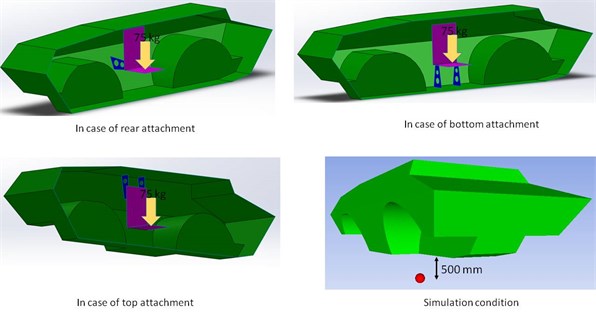
For the mathematic model of explosive material, the EOSJWL [2] model was enough to improve the accuracy of the result compare to the EOSGAM [2] which is good for fine mesh and large explosive distance. EOSIG [2] is good for explosive problem from chemical reaction until the end of blast. The analysis time was 4 microsecond to initially observe the trend of blast pressure wave and reduce the computational time.
In order to analyze, the stress distributed and deformation on the seat of each case were introduced. This indicates that the lowest deformation value exhibits a better design.
2.2. Blast analysis by approximation method
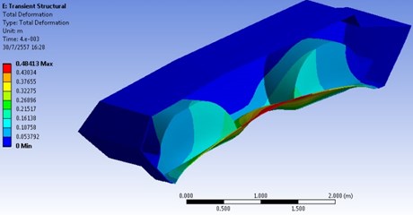
The interaction between fluid and structure in this case of explosive analysis is the pressure loading on the armored body. The load then transfers to the seat in the duration of time. To approximate the seat deformation, the side pressure is firstly calculated. When this pressure hit the face of armored body, it will transfer to the seat by passing brackets and then converting to be reflection pressure which is the loading act on the seat and the deformation can be calculated by the simple static structural finite element model.
According to TM 5-1300 [3] the side on pressure of free air burst can be determined step by step as follow:
Step 1. Hopkinson-Cranz scaling distance, .
where distance between structure and explosive (m), charge weight (kg).
Step 2. Determine side on pressure, shock front velocity, impulse.
Positive shock wave parameters for a spherical TNT Explosion in free air at sea level, are shown in Figure 2.
Fig. 2Positive shock wave parameters for a spherical TNT Explosion in free air at sea level
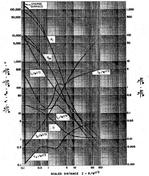
96.526 Bar: side on pressure, 3,048 m/s: shock front velocity, 11.70 Bar·ms: impulse during positive phase.
Step 3. Determine the normal reflection pressure of bursting air, .
Assuming the burst is an ideal gas with 1.4 and atmospheric pressure 10.1 Bar, we can find , [4]:
Step 4. Determine time of pressure loading at positive phase of burst pressure .
From Fig. 3 we can determine the impulse of reflect pressure 0.171 bar·s, [5].
By the relation of impulse to pressure we can determine as, [6]:
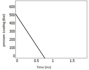
Step 5. Calculate armored body deflection by simply structural finite element model. The pressure profile of blast can be approximated by triangular shape of pressure and time as shown below, this is the loading which act on the structure.
Fig. 3Normally reflected blast wave parameters for spherical charge of TNT
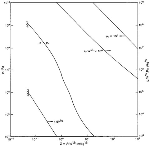
Fig. 4Blast analysis by approximation method
3. Results and discussion
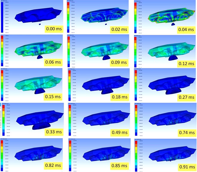
After the explosion had been started, the incidence pressure wave generated travels like a shockwave in the sphere shape. The pressure wave reached the armored body as shown in Figure 5. The figure show MIS.Stress (kPa) of each time. The pressure is transmitted through the armored vehicle hull throughout the vehicle components.
4. Conclusions
As noted, this paper focused on the comparison between the mine blast simulation suing Autodyne and approximation method. We concluded that both methods provide the satisfied results. However, the experiment is necessary to confirm the reliability of prediction results.
In addition, the behavior of transmitted pressure passed throughout the vehicle component particularly the seat attachment location and the seat was studied and investigated. The results demonstrated the distribution patterns of stress and displacement throughout the hull and seat structures led to the effective design of seat attachment location to maximize the trooper survivability by minimizing the deformation.
The top attachment location is the best design compared to the front and rear ones. However, the severe damage of the seat was observed, because of the effect of vehicle floor deformation that results in the direct contact between floor and seat allowing transmitted pressure from underneath.
Fig. 5Simulation Result (TNT off at 0.49 ms)
References
-
Piangpen P., Attapon C. Trooper seat attachment design and analysis. International Conference on Power and Energy Systems Engineering, 2014
-
Attapon C., Tawiwat V., Artit R. Suitable plate deflection angle to reduce blast strength for armored vehicle. International Conference on Natural Science and Environment, 2014.
-
Dytran 2013 Theory Manual. MSC Software Corporation, United State of America, 2013, p. 84-89.
-
Structures to Resist the Effects of Accidental Explosion. Departments of the Army, the Navy, the Airforce, TM 5-1300, United State of America, 1990.
-
ChockJeffrey M. K. Review of Methods for Calculating Pressure Profile of Explosive Air Blast and its Sample Application. Virginia Polytechnic Institute, United State of America, 1999.
-
Mays G. C., Smith P. D. Blast Effects on Buildings. Thomas Telford, London, 1995.
-
Ngo T., Mendis P., Gupta A., Ramsay J. Blast Loading and Blast Effects on Structures – an Overview. EJSE Special Issue: Loading on Structure, EJSE International, 2007.
-
Boyd Stephen D. Acceleration of a Plate Subjected to Explosive Blast Loading-Trial Result. DSTO Aeronautical and Maritime Research Laboratory, DSTO-TN-0270, Australia, 2000.
About this article
The authors would like to acknowledge Defence Technology Institute for Computational Resources.
