Abstract
A large number of brain injuries and casualties can be caused by the impact of bullets on the bullet-proof helmets, for which the underlying mechanisms are unclear and are likely to be complex. In the current study, an American advanced combat helmet was scanned to obtain 3-dimensional (3D) geometric information, from which a 3D finite element (FE) model of a ballistic helmet was developed. With this model, FE simulation was conducted and the results were compared with and verified by data from a ballistic test and a FE simulation study previously reported. Furthermore, the protective performance of the ballistic helmet was investigated using the FE model. The verification results show that the FE model of this ballistic helmet is effective, and data from the current study should be useful in providing theoretical guidance in the design of ballistic helmets.
1. Introduction
High-speed and high-energy shot/debris can impact on ballistic helmets considerably. In the cases of non-penetrating shots, the helmet deforms, and the brain can be seriously injured because of the direct contact of the inside of the helmet to the head and the impact waves passing onto the head. This phenomenon is called “rear effect” [1]. As the mechanical properties of high strength and high modulus fibers (such as aramid, ultra-high molecular weight polyethylene fibers) are improved, the nonmetallic bullet-proof helmet’s performance has been continuously enhanced and the helmets have become thinner and lighter [2]. Although the new lightweight bullet-proof helmets have reduced the percentage of the incidence of bullet penetration and mortality, the problem of the real effect caused by the high-speed bullets and fragments has become more acute. Rafaels et al. [3] discovered that among over 6000 casualty cases caused by bullets/fragments, over 70 % cases wore bullet-proof equipment at the time of injuries, and 50 % of brain injuries were caused by the rear effect [4]. Brain injuries due to this “rear effect” cause memory loss and sensorimotor dysfunction, reduce performance and slow down reactions, decrease the soldier’s combat ability, and even cause death. Mechanisms of brain damage caused by bullet/debris impact on bullet-proof helmets are likely very complex and are difficult to define. In addition, in the present time there are deficiencies in high speed and high energy impact tests and experimental evaluation studies. Therefore, scientific and engineering studies are currently required to investigate the mechanisms of the “rear effect” and to evaluate protective performance of bullet-proof helmets.
The majority of research on ballistic performance has been conducted on flat laminates. Van Hoof et al. studied the dynamic behaviors of the PASGT helmet subjected to ballistic impacts at different speeds and investigated the back-face (inside surface) deformation (BFD) of the helmet [5]. Aare and Kleiven developed numerical models of a human head and the combat helmet subjected to high speed ballistic impacts [6]. Tham et al. conducted experiments and AUTODYN-3D simulations using a spherical projectile travelling at 205 m/s and impacting a PASGT helmet [7]. However, the ballistic response of a helmet to high velocity impact can be different from that of a flat panel laminate. A number of authors have studied the effect of curvature on the impact resistance of a helmet. It was observed that the back-face deformation on a helmet induced by a projectile was greater than that on a flat panel fabricated from the same material [5]. Similarly, the curvature effect of the Kevlar ballistic helmet was investigated by Tham et al. [7], where the helmet was found to have a higher ballistic resistance than that of a Kevlar laminate. All these studies indicated that reducing the radii of curvature of a helmet increases its ballistic impact resistance. However, direct studies comparing the ballistic impact resistances of helmets with different curvature radii have not yet been performed.
The current study investigated the protective performance of bullet-proof helmets through the simulation method. The main objectives of this study were four folds: 1) to scan the American Army advanced combat bullet-proof helmet (ACH) and obtain its geometry information; 2) to develop the 3D finite element (FE) model of ballistic helmets and compare and verify it with existing experimental and simulation results in the literature; 3) using the model to predict the mechanical responses of bullet-proof helmets under impacting from different directions.
2. Materials and methods
2.1. Ballistic helmet model
The ACH (medium size) was chosen as the bullet-proof helmet for the current study. It can resist 7.62 mm bullets from type 54 of pistols within 5 m, and it is widely used in the United States Army (Fig. 1(a)). For the current study, according to the US National Institute of Justice standards [8] and the Department of Defense Test Standards V50 ballistic limit test [9], the inside and outside components of the helmet were removed, such as interior decorations and objects in suspension. Thus, only the helmet shell itself was used for developing the finite element model.
Firstly, the helmet was scanned using a 3D scanner, and its geometry information was obtained and saved in STL files (Fig. 1(b)). Then, the STL files were handled in point cloud format using the Geomagic software, and the accurate surface model was obtained (Fig. 1(c)-(f)). Subsequently, the model was changed into a solid entity; and after being meshed using hypermesh software, it was finally developed into the helmet’s 3D FE model (Fig. 1(f)-(g)). In addition, for simulation, analysis and calculation using this model, the LS-DYNA software was used. The flow-chart of the whole research process of the current study was shown in Fig. 1.
The finite element model was developed with the eight-node hexahedron, with the total numbers of 97874 units and 112992 nodes, and with each unit being 2 mm in size and 7.5 mm thickness. The element type of the helmet is Solid (SectSld).
2.2. Modelling of bullets and the equivalent body armour plate
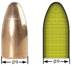
For the purposes of simulation, verification and NIJ-0106.01 standard test simulation [10], modelling was carried out for two kinds of bullets. One is a steel ball with 14.2 mm and 11.9 g, the other one is a bullet with 9 mm and 8 g. The finite element of the ball was modelled in an eight-node hexahedron, in which there are 3375 units and 4143 nodes, with each unit being 2 mm in size (Fig. 2(a)). Also, the finite element model of the pistol bullet was developed by an eight-node hexahedron, which has 19965 units and 21663 nodes, with each unit being 2 mm in size (Fig. 2(b)). The element types of the 14.2 mm spherical steel projectile and the 9 mm pistol bullet are Solid (SectSld).
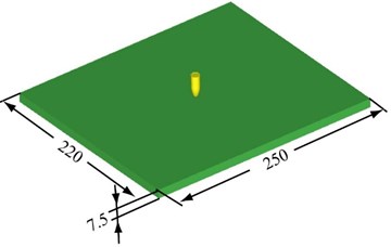
In order to compare and analyze the protective performance of the helmet and bullet-proof plates, according to the geometry and finite information of the helmet (thickness 7.5 mm, each unit 2 mm in size, including 112992 nodes and 97874 units), the current study used a bullet-proof plate which was equivalent to the helmet. The equivalent plate was a rectangular body with the size of 220×250×7.5 mm, with the same surface square as the helmet. The finite element model of the equivalent bullet-proof plate also used the eight-node hexahedron, with 110000 nodes and 94612 units and each unit being 2 mm in size (Fig. 2(c)). The element type of the equivalent bullet-proof plate is Solid (SectSld).
Fig. 1The finite element (FE) modelling process of a bullet-proof helmet and evaluation research process of its protective performance under impact loading
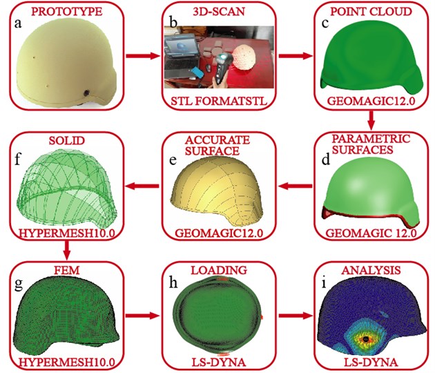
a) The bullet-proof helmet modelling process and the finite element simulation of bullet impact
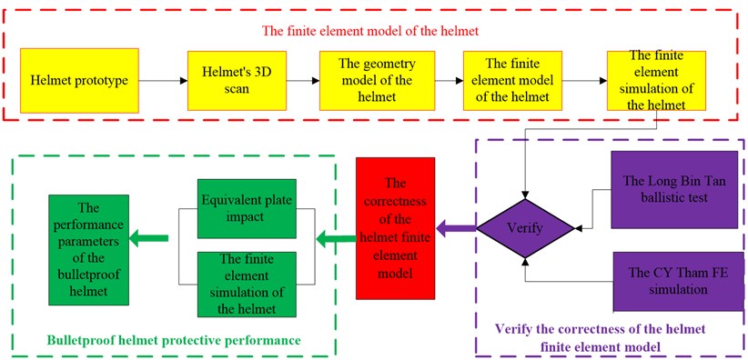
b) The research process flow-chart of the current study
2.3. Constitutive model and material parameters
The ball is made of elastic steel, and the bullet is made of elastic-plastic steel (with material parameters being shown in Table 1). The material of helmet is Kevlar [11]. For the bullet-proof plate, the same material parameters were chosen as for the helmet. For evaluating material performance, the constitutive model was used, which refers to failure criterion of chang-chang defining the fiber breakage, matrix cracking and matrix material failure and so on [12, 13]. The standard is based on stress failure rules. The chang-chang criterion classifies the failures of fiber and matrix into tension and compression failures, with the tensile failure including the fiber fracture and matrix cracking. In addition, previously developed composite failure criteria [14] were utilized to predict failures in matrix cracking, matrix compression, fiber-matrix shear-out and fiber breakage.
Fig. 2Finite element modeling of bullets and the equivalent bullet-proof plate: a) a 14.2 mm spherical steel projectile, b) a 9 mm pistol bullet, c) an equivalent bullet-proof plate
a)
b)
c)
Table 1Material properties of the bullets used in the study
Bullet types | (kg/m3) | (GPa) | Yield stress (GPa) | Tangent modulus (GPa) | |
Spherical steel projectile | 7850 | 210 | 0.33 | ||
9 mm pistol bullet | 8110 | 206 | 0.30 | 0.28 | 0.69 |
Table 2Material properties of the ballistic helmet and bullet-proof equivalent plate [14, 15]
(kg/m3) | (GPa) | (GPa) | (GPa) | (GPa) | (MPa) | (MPa) | (GPa) | (GPa) | (GPa) | ||
1230 | 18.5 | 18.5 | 6 | 0.25 | 0.33 | 0.77 | 2.5 | 0.558 | 0.555 | 0.555 | 1.086 |
The fiber breakage failure criterion is defined as follows:
where is the failure index for fiber fracture, is the longitudinal tensile strength, is normal stress (0), and is given as follows:
In Eq. (2), is the shear modulus, is shear stress, is the longitudinal shear strength, and is a nonlinear shear stress parameter defined by the material’s shear stress-strain measurements, which should have a value between 0 and 0.5 [13].
The matrix cracking failure criterion is defined as follows:
where is matrix cracking failure index, is the transverse tensile strength. is normal stress (0).
The matrix compression failure criterion is defined as follows:
where, is the transverse compressive strength, and is normal stress (0).
When the failure criterion of chang-chang was used, all the same kinds of the fiber composite materials could not imitate the compression failures and fiber delamination.
When the Eq. (1) is satisfied (1), all of the elastic constants of the failed lamina are set to zero (i.e., 0).
When the matrix cracking failure criterion in Eq. (3) is satisfied (1), all of the elastic constants except for the fiber modulus are set to zero.
2.4. Validation
To verify the effectiveness of the bullet-proof helmet FE model, experimental data were obtained and used from studies of C. Y. Tham [7] and B. T. Long [16], where the front/side impact tests were conducted with a ballistic helmet prototype and with a ballistic gas gun. The experiments were designed to evaluate the protective performance of ballistic helmets under frontal and lateral impacting. Experimental data primarily contained the launcher unit, gun barrel and target chamber. The emitting device was a type of high-pressure air chamber, and it was connected to a gas cylinder. A high-pressure gas was pumped into the gas chamber, and then the chamber was opened by valves. The pressure of the released air had the ability of pushing the projectile (the steel ball) of 11.9 g and 14.2 mm. The helmet was placed on a steel platform and fixed by three constraint points as shown (Fig. 3). The steel ball was launched at a speed of 205 m/s to 220 m/s from the trajectory. The helmet was impacted in the front and by the side by the high-speed steel ball. The speed of the steel ball was measured by a speedometer, and meanwhile, the rebounding of the bullet was caught by a high-speed camera, when the bullet shot the helmet.
In the finite element simulation, the helmet’s freedom of movement was limited to 6 directions (, , and three directions of movement and rotation). The front face of the helmet was impacted by the steel ball with all the nodes loaded with the speed of 205 m/s, and the lateral impact by the steel ball with all the nodes loaded with the speed of 220 m/s. The contact between the bullet and helmet was defined as contact-eroding-surface-surface, the helmet itself contact was defined as contact-automatic-single-surface. The coefficients of static and dynamic friction were set to 0.3 and 0.28, respectively.
2.5. Evaluation of protective performance of the bullet-proof helmet
After verifying the effectiveness of the helmet FE model, this model was used to evaluate the bullet-proof helmet’s protective performance upon impact by a non-penetrating bullet. The work had two parts that were carried out by simulation. The first part was the finite element simulation of the bullet-proof helmet, the other part was a simulation of the equivalent bullet-proof plate. Both the helmet’s and equivalent plate’s finite element models were loaded the same impact pressure. These simulations enabled obtainment of the inside surface’s maximum relationships between deformation with time, the impact force with time, the impacting energy with time, the internal energy conversion with time, and the stress with strain.
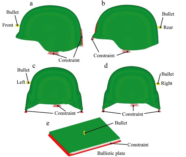
The loading standards for the current study (Fig. 3) used those of the V50 ballistic limit test [17]. The V50 simulation experiment was carried out with the NIJ-0106.01 standard (Table 3). The helmet was fixed on a steel platform by three constraint points. Its freedom of movement was limited to 6 directions (, , and three directions of movement and rotation). The helmet was impacted respectively at the front (Fig. 3(a)), the back (Fig. 3(b)), the left (Fig. 3(c)) and the right (Fig. 3d) sides. The equivalent bullet-proof plate was also fixed on a steel platform and the freedom of movement was limited to 6 directions (, , and three directions of movement and rotation). It was impacted directly at the front and the constraint condition as shown in Fig. 3(e). During the test, the distance between gun and the object was 5 meters. The 9 mm pistol bullet was launched from the gun and struck the object at the speed of 426±15 m/s. Since the study’s focus was on the bullet-proof protective performance, the bullet speed of 426 m/s was chosen.
After comparing results from the FE simulation of the ballistic helmet with those from bullet-proof equivalent plate impact simulation, the helmet’s bullet-proof performance was evaluated.
Table 3NIJ-0106.01 test standards [8]
Helmet size | Helmet weight | Impact locations | Velocity (m/s | Results |
Medium | 1.41 kg | Front | 424 | Partial penetration |
Back | 430 | Partial penetration | ||
Right | 430 | Partial penetration | ||
Left | 427 | Partial penetration |
Fig. 3Bullet-proof helmet and equivalent bullet-proof ballistic plate performance studies
3. Results
3.1. Validation of the bullet-proof helmet finite element model
The current study has developed a 3D finite element (FE) model of a bullet-proof ballistic helmet based on the process as shown in Fig. 1. For the purposes of simulation, verification and evaluation of the ballistic bullet-proof helmet performance, FE modelling was also developed for two kinds of bullets (a steel ball and a pistol bullet) as shown in Fig. 2. To verify the effectiveness of this model of bullet-proof helmet, simulation was carried out with this FE ballistic helmet model, and deformation and damage data were compared between the ballistic tests in C. Y. Tham’s study [7], reported simulated data [16], and our helmet’s finite element simulation (Fig. 3 and Table 3).
While the steel ball did not penetrate the helmet, the helmet was damaged to some extents. Indentation was obvious in the affected area of the helmet, with the maximum deformation area found in the impacting center of the bullet and helmet (Fig. 4 and Table 4). In the front of the bullet-proof helmet, a permanent damage area was apparent with a diameter of 42 mm in the ballistic test, of 32 mm in the literature, and of 28 mm in our finite element simulation. In the side test, the damage area diameter was 32 mm, 32 mm and 42 mm, respectively. In addition, deformation values of the inside surface of the bullet-proof helmet were 15 mm in the front ballistic test, 6.4 mm reported in the literature, and was 6.5 mm in our finite element simulation; and similarly, the inside surface deformation values were 18.7, 10.4, and 9.6 mm, respectively in the side test, in the literature and in our simulation. For the maximum energy absorption, the values were 251.3 J in the frontal ballistic test, 284.4 J reported in the literature, and 250.0 J in our finite element simulation; and these values were 285.3, 278.9, and 287.9 J in the lateral ballistic test, in the literature and in our finite element simulation. These comparisons suggest that, while there are some numerical differences between the prototype ballistic test and finite element simulation, the data from the literature are more similar to the results of our simulation. Thus, the finite element model of the bullet-proof helmet is effective to a good extent.
Fig. 4Ballistic helmet prototype test [7] and helmet deformation finite element simulation
![Ballistic helmet prototype test [7] and helmet deformation finite element simulation](https://static-01.extrica.com/articles/16497/16497-img7.jpg)
Table 4Comparisons of data from the prototype ballistic test, reported in literature and from the finite element simulation
Impact direction speed of bullet | Front 205 m/s | Side 220 m/s | ||||
Comparisons | Ballistic test [7] | Simulation [16] | FE simulation | Ballistic test [7] | Simulation [16] | FE simulation |
Permanent dent region (mm) (diameter) | 42 | 32 | 28 | 42 | 32 | 32 |
Maximum inside surface deformation (mm) | 15 | 6.4 | 6.5 | 18.7 | 10.4 | 9.6 |
Energy absorbed by helmet (J) | 251.3 | 284.4 | 250.0 | 285.3 | 278.9 | 287.9 |
3.2. The bullet-proof performance
Simulation results of the inside surface maximum deformations of the helmet at different locations are shown in Table 5 together with those of the equivalent bullet-proof plate under 9 mm bullet impacts at 426 m/s. Among the five locations of the helmet, while the maximum deformation at the front was 11.2 mm, deformation at the left and right sides was 8 to 9 mm. On the other hand, deformation of the equivalent bullet-proof plate reached 14 mm. These results demonstrate that inside surface deformation of the bullet-proof helmet varies at different locations with the left and right sides having the smallest deformations, and that deformation of the bulletproof equivalent plate was larger than those of the helmet.
The relationship of the inside surface deformation with time was presented at Fig. 5 comparing different locations of the bullet-proof helmet and the equivalent plate. It can be seen that, once the bullet made the contact, the helmet and plate transformed rapidly. In particular, they deformed faster in the first 0.05 ms, and then slowed down between 0.05-0.12 ms.
Fig. 5The time-dependent inside surface deformations at different locations of the bullet-proof helmet in comparison with the equivalent bullet-proof plate under 9 mm bullet impacts at 426 m/s
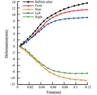
Table 5Inside surface deformations of the helmet and equivalent bullet-proof plate under 9 mm bullet impacts at 426 m/s
Impact locations | Front | Back | Left | Right | Equivalent plate |
Deformation (mm) | 11.2 | 10.5 | 8.4 | 8.8 | 14 |
Correspondingly, the maximum contact force of the helmet or plate with the impacting bullet occurred at the maximum deformation in the current impacting simulation test (Fig. 6). At the peak force of the contact, the maximum contact force with the equivalent plate was around 60 KN, and the peak force with the bullet-proof helmet (around 68KN) was similar on all sides. However, in the latter half of the impact, the contact force’s rates of decline on the left and right sides were slower than the front and back directions.
Fig. 6Contact force – time relationship at different locations of the bullet-proof helmet in comparison with the equivalent bullet-proof plate under 9 mm bullet impacts at 426 m/s
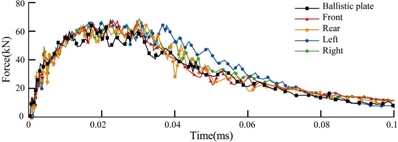
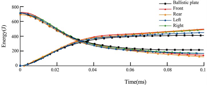
Fig. 7 shows charts of the kinetic energy and internal energy conversion for the bullet impacting different locations of the helmet and the equivalent plate. The total energy was 700 J; and when the helmet or plate was impacted by the bullet, the kinetic energy declined, and internal energy rose. The kinetic energy of the bullet from 0-0.10 ms was quickly converted to internal energy, as after 0.1 ms most of the kinetic energy had been absorbed and the energy transformed relatively flat. Since that point, the deformation was small, and the bullet began to rebound. Since the left and right sides of the contact and deformation were bigger than those of the front and back of the helmet, the left and right sides showed a stronger resistance to deformation and consequently a bigger contact stiffness performance than the front and back. It is known that the greater the contact stiffness, the slower the kinetic energy and internal energy are converted. Therefore, the bigger contact stiffness and thus a slower conversion between kinetic energy and internal energy led to a bigger contact force in the left and right sides than the front and back. For the equivalent plate, due to the larger deformation, its contact stiffness and contact force were lower, and kinetic energy and internal energy conversion was faster.
Fig. 7Impact energy and internal energy conversion – time relationship at different locations of the bullet-proof helmet in comparison with the equivalent bullet-proof plate under 9 mm bullet impacts at 426 m/s
The stress-strain simulation results of the helmet and the equivalent plate following the bullet impact are presented in Fig. 8. Results indicate that the 7.5 mm equivalent plate was not defeated (penetrated) by the 9 mm 426 m/s bullet. The maximum stress of the helmet was 1988 MPa in the front, 1609 MPa in the back, 1837 MPa in the left side, and 1704 MPA in the right side. Comparatively, the maximum pressure on bullet-proof equivalent plate was 1392 MPa. These results indicate that impacting stress was the biggest at the front and lowest at the bullet-proof equivalent plate, suggesting that the geometric shape of helmet confers a certain influence on the bullet-proof performance.
3.3. Characteristics of bullet deformations
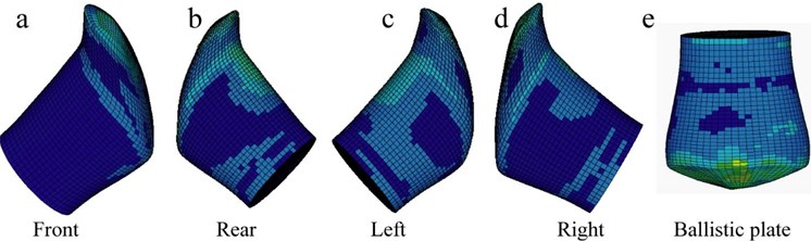
In the above simulations of the helmet or the equivalent bullet-proof plate being impacted by the bullet, the bullet was also shown to have large deformations, the characteristics of which are shown in Fig. 9(a)-(d). It can be seen that, after the high-speed impacting, the bullet’s deformations have some certain characteristics and patterns. At the initial stage, it was elastic deformation. When the material property of the bullet reached the yield strength, the bullet showed a large plastic deformation followed by an elastic deformation. In addition, all deformations were shown to occur in the direction towards the top of the helmet, and the stress force of the bullet also shifted toward the direction of the helmet with a smaller curvature (Fig. 9(a)-(d)). Furthermore, during the impact process, the bullet deformation caused some slipping movement on the helmet; and this movement would consume a certain amount of impact energy, which would increase the absorption of energy and thus reduce the inside surface deformation of the helmet to a certain extent.
In the simulation of the equivalent bullet-proof plate being impacted by the bullet, the deformation form was mainly elastic at the initial stage. But when it reached the yield limit, the bullet began to become larger in volume, until the bullet's kinetic energy was absorbed and the deformation stopped (Fig. 9(e)).
Fig. 8Comparisons of the simulation stress-strain results between the helmet at different locations: a) front, b) rear, c) left, d) right and e) bullet-proof equivalent plate under 9 mm bullet impacts at 426 m/s
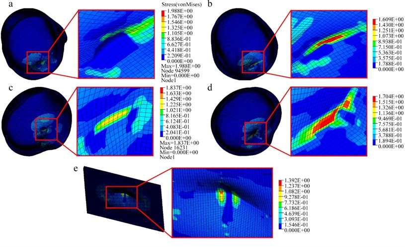
Fig. 9The deformation characteristics of the 9mm bullet after impacting at 426 m/s at different locations of the bullet-proof helmet or the equivalent bullet-proof plate
4. Conclusion
Mechanisms are unclear for the rear effect and brain damage caused by the bullet impact on bullet-proof helmets. The current study has developed a finite element model of the US Army advanced combat helmet prototype using its scanned 3D geometry information. In addition, using reported bullet-proof helmet ballistic test results and finite element simulation data [7, 16], this study has verified the correctness and effectiveness of this ballistic helmet finite element model. Furthermore, by conducting simulations using this finite element model and examining the mechanical responses of the helmet and the equivalent bullet-proof plate, the current study has obtained the bullet-proof performance of this ballistic helmet.
By comparing degrees of inside surface deformations at the four impacted locations of the helmet, we showed that the maximum deformation occurred at the frontal impact position, and that deformations in the left and right sides were similar and the smallest. Our simulation results also demonstrated that inside surface deformations and the performance of the ballistic resistance of the helmet were also different at the four impact locations. Our data suggest obvious relationships between the degree of deformation, the location of the impact center, and the area of the deformation. At the front of the helmet, the area withstanding the deformation was the smallest, and thus the inside surface deformation was biggest. Due to consideration of the visual area and ergonomics in design, the front structure areas of the multi-function bullet-proof helmets have reduced; however, based on our data of the current study, the reduction of the frontal area of ballistic helmets would reduce their ability of ballistic resistance. Our study suggests that it is indispensable to consider the influence of these factors in the designing of ballistic helmets.
Based on the degrees of inside surface deformations, the front of the helmet showed the lowest ballistic resistance and the two sides of the helmet shared the best performance. This is most likely due to the fact that the impacted location on the front side was closer to the edge of the helmet than the locations of the other sides, which reduced the ballistic resistance. When the impact location is closer to the edge, the area allowed for dissipation of the absorbed energy is reduced, which results in an increased damage in the impact location. On the other hand, both lateral sides of the helmet showed almost the same ballistic performance due to the similar shape of both sides. Since the bending of the woven fabric reduces the bullet-proof performance [18, 19], the relatively flatter shape of both sides of the helmet showed better bullet-proof performance when compared to the front and back sides. Our simulation results are consistent with the NIJ-0106.01 standards [9]. Our study suggests that effects of the helmet geometry on its ballistic performance should also be considered in the helmet design process.
Considering the deformation characteristics and the results compared with plate, the deformable bullet was found to move (slide on the surface) toward the top of the helmet with a small curvature. There was a relatively large slide on the surface, and the process of sliding quickened the transformation of kinetic energy and internal energy, thus enabling a better energy absorption effect of the helmet. On the other hand, it can also explain that the deformable steel Buckshot bullets have worse striking capabilities than non-deformable ones.
References
-
Yang Z. Z., Dai J. H. Simulation-based assessment of rear effect to ballistic helmet impact. Computer-Aided Design and Applications, Vol. 7, Issue 1, 2010, p. 59-73.
-
Kulkarni S. G., Gao X. L., Horner S. E., Zheng J. Q., David N. V. Ballistic helmets – their design, materials, and performance against traumatic brain injury. Composite Structures, Vol. 101, 2013, p. 313-331.
-
Rafaels K. A., Cutcliffe H. C., Salzar R. S., Davis M., Boggess B., Bush B., Dale’Bass C. R. Injuries of the head from backface deformation of ballistic protective helmets under ballistic impact. Journal of Forensic Sciences, Vol. 60, Issue 1, 2015, p. 219-225.
-
Hoge C. W., Castro C. A., Messer S. C., McGurk D., Cotting D. I., Koffman R. L. Combat duty in Iraq and Afghanistan, mental health problems, and barriers to care. New England Journal of Medicine, Vol. 351, Issue 1, 2004, p. 13-22.
-
van Hoof, Cronin D. S., Worswick M. J., Williams K. V., Nandlall D. Numerical head and composite helmet models to predict blunt trauma. 19th International Symposium on Ballistics, Interlaken, Switzerland, 2001.
-
Aare M., Kleiven S. Evaluation of head response to ballistic helmet impacts using the finite element method. International Journal of Impact Engineering, Vol. 34, 2007, p. 596-608.
-
Tham C. Y., Tan V. B. C., Lee H. P. Ballistic impact of a KEVLAR® helmet: experiment and simulations. International Journal of Impact Engineering, Vol. 35, 2008, p. 304-318.
-
Ballistic Standard for Ballistic Helmets. Standard-0106.01, U.S. Department of Justice National Institute of Justice, 1981.
-
Military Specification: Helmet, Ground Troops and Parachutists. MIL-H-44099A, Department of Defense Test Standards, 1986.
-
Shaoo D., Deck C., Yoganandan N., Willinger R. Influence of stiffness and shape of contact surface on skull fractures and biomechanical metrics of the human head of different population underlateral impacts. Accident; Analysis and Prevention, Vol. 80, 2015, p. 97-105.
-
Technical Guide for KEVLAR Aramid Fiber. H-77848, Du Pont, 2000.
-
van Hoof J., Deutekom M. J., Worswick M. J., Bolduc M. Experimental and numerical analysis of the ballistic response of composite helmet materials. Proceedings of 18th International Symposium on Ballistics, San Antonio, TX, USA, 1999.
-
van Hoof J., Cronin D. S., Worswick M. J., Williams K. V., Nandlall D. Numerical head and composite helmet models to predict blunt trauma. Proceedings of 19th International Symposium on Ballistics, Interlaken, Switzerland, 2001.
-
Chang F. K., Chang K. Y. A progressive damage model for laminated composites containing stress concentrations. Journal of Composite Materials, Vol. 21, 1987, p. 834-855.
-
Hallquist J. O. LS-DYNA Theory Manual. Livermore Software Technology Corporation, Livermore, CA, 2006.
-
Tan L. B., Tse K. M., Lee H. P., Tan V. B. C., Lim S. P. Performance of an advanced combat helmet with different interior cushioning systems in ballistic impact: experiments and finite element simulations. International Journal of Impact Engineering, Vol. 50, 2012, p. 99-112.
-
Li Y. Q., Li X. G., Gao X. L. Advanced combat helmet under ballistic impact. Journal of Applied Mechanics, Vol. 82, Issue 11, 2015p. 111004.
-
Lim C. T., Shim V. P. W., Ng Y. H. Finite-element modeling of the ballistic impact of fabric armor. International Journal of Impact Engineering, Vol. 28, 2003, p. 13-31.
-
Kulkarni S. G., Gao X.-L., Horner S. E., Zheng J. Q., David N. V. Ballistic helmets – their design, materials, and performance against traumatic brain injury. Composite Structures, Vol. 101, 2013, p. 313-331.
Cited by
About this article

Z. C. is supported by the National Natural Science Foundation of China (51405153), the Key Planned Science and Technology Project of Hunan Province, China (2015NK3031). L. W. is supported by the Australian National Health and Medical Research Council (NHMRC) Postgraduate Research Scholarship Grant, J. D. is supported by the Australian Postgraduate Award (APA) Ph.D. scholarship and Vice Chancellor and President’s Scholarships (University of South Australia), and C. J. X. is supported by the NHMRC Senior Research Fellowship.
