Abstract
The aim of this paper is to investigate combination of vibration isolation for four vibrating machines with eight unbalanced rotors to eliminate the dynamic forces that the system acts on the foundation. By using the average method of modified small parameters and modal analysis, we deduce the dimensionless coupling equations of the eight unbalanced rotors, which convert the problem of synchronization for the eight unbalanced rotors into that of existence and stability of zero solutions for the dimensionless coupling equations. By combining the existence of zero solutions for the dimensionless coupling equations with the general dynamic symmetry for two coupled unbalanced rotors in one vibrating machine, the synchronization criterion and the stability criterion are obtained by using the generalized Lyapunov equation, Lyapunov criterion and Routh-Hurwitz criterion. Computer simulations are carried out to verify the above theoretical results. The results of computer simulation demonstrate that a pair of unbalanced rotors in one vibrating machine can synchronize at a phase difference of , the phase differences among the four vibrating machines are between the two opposite. The four vibrating machines can vibrate only in -direction, while the isolation frame is at rest during the working process. When the power supply of one motor in any vibrating machine is switched off, the coupling characteristics of the system can transfer energy from the unbalanced rotors with power supply to that without power supply to extend synchronization of the eight unbalanced rotors.
1. Introduce
Synchronization phenomena in large populations of interacting elements are found in many scientific fields, such as in physical, biological, chemical, and social systems [1]. One of them is synchronization of unbalanced rotors (URs) in vibrating systems. About sixty years ago, at the Institute Mekhanobr in Leningrad, it was accidentally discovered that two URs driven by two motors on a single base trended to operate synchronously, later Dr. Blekhman in the Soviet Union gave the first theoretical explanations of this synchronization phenomenon. Using the method of direct separation of motions and the Poincare-Lyapunov small-parameter method, Blekhman proposed the synchronization theory of vibrating machines with two or more URs, and has successfully solved a number of self-synchronization [2-6]. Taking the phase difference between the two URs as one small parameter, Wen developed the theory of two URs in vibrating systems and established the branch of vibration utilization [7, 8].
Synchronization of URs in vibrating systems stems from general dynamic symmetry [9] and motion selection characteristics of system [10], which rely on the distribution of the URs and the structure of vibrating systems and lock the phase differences among the URs as deterministic values [7-12]. In a single freedom vibrating system with two identical URs rotating in opposite directions, the vibrations excited by the two URs would be canceled mutually and the system is at rest [2]. In plane motion vibrating systems with two URs, the vibrating mass can undergo a linear, or an elliptical, or a centroid swing motion [7]. In a spatial motion vibrating system with two URs, the vibrating mass can undergo a linear motion and a swing one [11]. In a three-mass vibrating system with four URs rotating in the same direction, the four URs can excite the elliptical motion of the primary mass [12].
In this paper, the synchronization for an octa-motor vibrating system with two-stage vibration isolation is investigated to eliminate the dynamic forces that the system acts on the foundation during its working process. The rest of this paper is organized as follows: the equations of motion of the system and the dimensionless coupling equations of the eight URs are derived in Sections 2 and 3, respectively. Then the criterion of synchronization and that of stability for its synchronous state are given in Section 4. Numeric discussions are given in Section 5 and conclusions are made in Section 6.
2. Equations of motion of a vibrating system
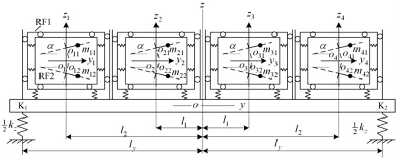
Fig. 1 shows the dynamic model of a vibrating system with eight URs. The vibrating system consists of four identical vibrating machines (VMs), which are supported on an isolation rigid frame (IRF) and marked as , , and . Every VM is composed of a supporting rigid frame and a material one, denoted by RF1 and RF2, respectively. RF2 is connected with RF1 by soft springs in - and -directions. RF1 is connected to the IRF by springs in -directions, and fixed in - and -directions. The IRF is supported by an elastic foundation. Two induction motors rotating in the same direction on the top view are supplied with the same power supply and installed in each RF2. Each drives one UR. The rotational planes of the two URs are symmetric about -plane, and the angle between each rotational plane and -plane is . The IRF has six degrees of freedom. The motions of the IRF are vibrations in -, - and -directions, denoted by , and , and swings about -, - and -axis, denoted by . The motion of the RF2 for in -direction is denoted by . The motions of each RF2 for in - and -directions are denoted by and . The phase angle of the two URs for are denoted by and , respectively. Comparing with the masses of the RF1 and RF2, the mass of an UR is very small, i.e., , . Hence, the inertia coupling due to the symmetry of the two URs can be neglected. Using the Lagrange’s equations, and choosing , , , , , , , ,…, , , , , ,…, , , as the generalized coordinates, we derive the differential equations of motion of the vibrating system as follows:
where and denote and , respectively. Other parameters in the formulas are as follows:
Fig. 1Dynamic model of the considered vibrating system
3. Dimensionless coupled equations of the eight URs
Because the URs rotate periodically, the vibrations of the vibrating system is also periodic. When the system runs stably, the average instantaneous phase of the eight URs is assumed to be and the least common multiple period of the eight URs is assumed to be , the average instantaneous angular velocity is and the average value of over the time must be a constant:
If the coefficient of the instantaneous change of is assumed to be , the instantaneous average angular velocity can be expressed as follows:
Assuming:
Then we have:
Assuming , 1, 2,…,8, then we have:
that is:
Because the slips of induction motors are very small during the steady state operation, the angular acceleration of the URs in Eqs. (1) can be neglected, i.e., . The exciting frequency is much greater than the natural frequency of the vibrating system and the damp is much small. In this case, the effect of the coefficients of the angular velocities on the amplitude and phase angle of response of the vibrating system can also be neglected. Inserting Eq. (4) into the equations of vibration in Eq. (1) yields:
According to the coupling relation, Eqs. (7) are divided into two groups, denoted by A and B. The general coordinate vector of Group A is:
Equations of Group A are divided by and are written in a matrix form as the following:
where, .
The general coordinate vector of Group B is:
and its matrix form of equations are:
Eq. (8) and (9) are coupling equations. It is assumed that the damping is proportional, i.e., the damping matrix is a linear combination of the mass and stiffness matrices:
Assuming that the normalized mode matrices for Eqs. (8) and (9) are and , respectively, the normalized coordinate transformations are defined as follows [13, 14]:
Inserting Eq. (11) into Eqs. (8) and (9) and multiplying both the sides of the equations by and , respectively, yield:
then Eqs. (8) and (9) become:
with:
Eq. (13) can be written as follows:
where and is the natural frequencies of the coupling system for Groups A and B, respectively. and are the modal damping ratios for Groups A and B, respectively.
The responses of Eqs. (15) can be expressed as follows:
The symbols in Eqs. (15) and (16) are listed in Appendix A.
Inserting Eqs. (16) into Eqs. (11) yields the responses of Eqs. (7) as follows:
In a quasi steady-state, the electromagnetic torque of an asynchronous motor can be expressed as the following [11, 12]:
where and are the electromagnetic torque and the stiffness of angular velocity when the motor operates at the angular velocity of , respectively.
The moment of inertia of each UR is equal to summation of that of the eccentric lump and that of the motor’s rotor. Compared with that of the eccentric lump, the moment of inertia of the motor’s rotor is very small and can be neglected. Inserting Eq. (18) into the equations of URs in Eq. (7) and integrating them over yield their single period average equations as the following:
where ““ represents the average value over one period. The symbols in Eq. (19) are listed in Appendix B.
and represent the coupling coefficients of the sine and cosine for URs and , respectively [11]. The transmission paths between any two URs are the same, therefore, we have:
Dividing Eq. (19) by and writing it in a matrix form yield:
where:
Eq. (21) is called the dimensionless coupling equations of the eight URs.
4. Synchronization of the eight unbalanced rotors
4.1. Synchronization criterion
Assuming in Eq. (21), we obtain , i.e.:
where refers to the output electromagnetic torque of motor , which is the difference between the electromagnetic torque of one motor and the friction torque of its rotor. is the kinetic energy of one standard UR, .
Inserting Eq. (4) into Eq. (22) yields:
According to the general dynamic symmetry of the vibrating system, the phase difference between two URs in a vibrating system can be driven to their generalized dynamic symmetry angles by the general dynamic torque [9, 11]. For the structural symmetry of every vibrating machine in Fig. 1, the coefficient of synchronization increases with the decrease of the inclination angle [15, 16]. Hence, the two URs in one VM can synchronize at the phase difference of by adjusting the inclination angle and excite vibration of vibrating mass in -direction, i.e.:
where . Then we have:
In this case, the two URs in one VM can be taken as one UR. Then the two motors in one VM can be taken as one motor, the output electromagnetic torque is:
By Eq. (26), the differences of the output torque for the two motors between two of the four VMs can be obtained and expressed as follows:
Inserting Eqs. (23) and Eqs. (25) into Eqs. (27) and rearranging them yield:
The functions , which are listed in Appendix C, are limited functions of , and [17], i.e.:
If the left hand of Eq. (28) is denoted by , then when the parameters of the system satisfy the following condition:
E. (26) can be solved for , , and , which are denoted by , , and , respectively. Eq. (30) are synchronization criterion for the four vibrating machines, while Eqs. (24) and (30) are synchronization criterion of the vibrating system.
4.2. Synchronization stability
Substituting into Eq. (21), we can obtain:
Obviously, , i.e., the generalized system, Eq. (31), is positive definite [18]. When the parameters of the vibrating system satisfy the conditions:
The generalized system, Eq. (31), satisfies the generalized Lyapunov equations [18, 19]:
If the generalized system, Eq. (31), is stable [19]. Treating mathematically Eq. (24) in the following manner: Introducing the parameters, , assuming that the solutions of the Eq. (23) are , ,…, , linearizing Eq. (24) at these points and dividing them by , respectively, we can obtain:
where is the value of when 1,…, 7.
Adding eight formulae from Eqs. (33) to (41) and rearranging it, we have:
Subtracting Eq. (35) from Eq. (34), and rearranging it, we obtain:
Subtracting Eq. (37) from Eq. (36) and rearranging it, we obtain:
Subtracting Eq. (37) from Eq. (36) and rearranging it, we obtain:
Subtracting Eq. (39) from Eq. (38) and rearranging it, we obtain:
Subtracting summation of Eqs. (40) and (41) from that of Eqs. (34) and (35), and rearranging it, we obtain:
Subtracting summation of Eqs.(38) and (39) from that of Eqs. (36) and (37), and rearranging it, we obtain:
Subtracting summation of Eqs. (36)-(39) from that of Eqs. (34), (35), (40) and (41), rearranging it, we obtain:
Eq. (43) to (49) can be written into a matrix form as the following:
By assuming exponential time-dependence of the form and inserting it into Eq. (50), the determinant equation can be solved, and the characteristic equation for eigenvalue can be obtained as:
The zero solutions of Eq. (50) are stable if and only if all the roots of in Eq. (50) have negative real parts. In according to the Routh-Hurwitz criterion, when Eq. (52) is satisfied [20]:
, where is the th Hurwitz determinant. Eqs. (32), (33) and (52) are the stability criterion of synchronization.
5. Computer simulation
In this section, an example is presented to investigate the main results of the above theoretical analysis clearly. To verify the ability of self-synchronization of the vibrating system, the parameters of the eight motors are assumed to be different. The parameters of the vibrating system are as follows: 1000 kg, 300 kg, 2200 kg, 0.2 m, 40 kg, 1600 kgm2, 0.01, 1, 2,…, 8; 0.07 [8-12].
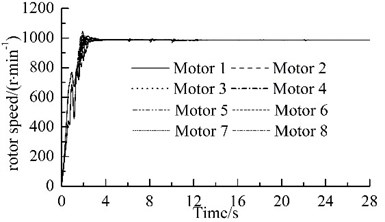
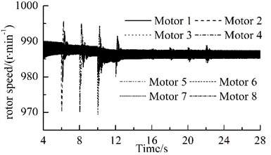
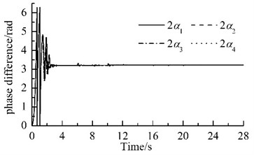
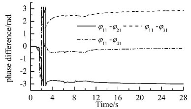
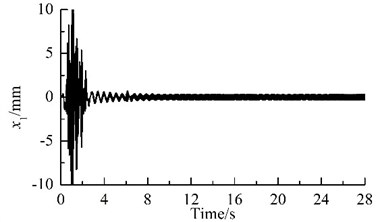
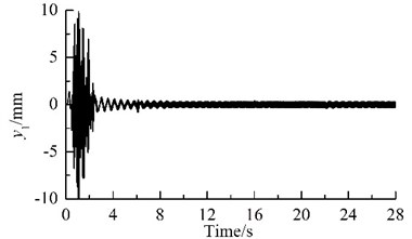
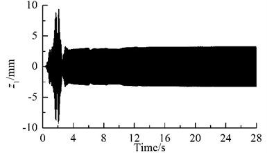
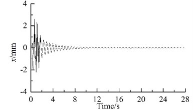
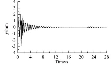
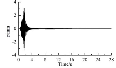
Fig. 2 shows results of computer simulation. Because the parameters of the two motors in one VM are different, the rotational speeds of the two motors are different, and the phase difference between each pair of the URs also change periodically, as illustrated in Figs. 2(a) and (c). With the increase of the rotational speed for the motors, the general symmetry torques take the role of driving the phase differences close to their general symmetry angles [10]. Hence, the motors synchronize rapidly at a rotational velocity of 988.5 r/min, and the phase difference between the two URs in each VM stabilizes in the vicinity of 1.018, as illustrated in Fig. 2(a), (b) and (c).
Fig. 2Results of computer simulation for the vibrating system
a)
b)
c)
d)
e)
f)
g)
h)
i)
j)
Because the synchronization ability among the four vibrating machine is more infirm than that of the two URs in one VM, the phase differences between two of the four VMs stabilize more slowly, as compared Fig. 2(c) with Fig. 2 (d). In this case, the exciting forces of the two URs in each VM in - and -directions are cancelled mutually and that in -direction are superposed mutually. Hence, owing to the damping effect, - and - resonant responses of the corresponding mass in the starting process disappear gradually, and -response becomes a harmonic motion, as illustrated in Fig. 2(e), (f) and (g). Furthermore, the phase differences between two of the four VMs are opposite mutually, the forces that the four VMs act on the IRF are cancelled mutually. Therefore, the resonant responses of the IRF occurring in the starting process are cut down gradually by the damping, as illustrated in Figs. 2(d), (h)-(j). This fact demonstrates that the four VMs installed symmetrically on one IRF can eliminate the dynamic forces of the foundation.
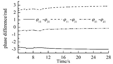
The power supplies of motors 2, 4, 6 and 8 are switched off when time is 6 s, 8 s, 10 s, and 12 s, respectively. When time is 16s, 18s, 20s, and 22s, the URs 2, 4, 6 and 8 are subjected to the phase disturbances of /9, 2/15, /6, and /3, respectively. The detailed variations of phase differences for the system are illustrated in Fig. 3. When the power supply of one motor is switched off, its rotational speed and its corresponding phase difference fluctuate violently, but they stabilize rapidly and the eight URs rotate synchronously at a slightly lower rotational speed, as shown in Fig. 2(b) and Fig. 3(a). The phase differences are: , , and . When the phase difference of one UR is disturbed, the rotational speed fluctuates slightly. In all the above processes, the rotational speed of the system always operates synchronously; the synchronous speed is 987.5 r/min, 987 r/min, 986.5 r/min, and 986 r/min, respectively, as illustrated in Fig. 2(b). The phase difference between two of the four VMs vary slowly, as illustrated in Fig. 3(b). These facts demonstrate that the coupling characteristics of the considered system can transfer from the motors with power supply to that without power supply and allow that the system operates synchronously. This phenomenon is found in Ref. [21], which claimed that synchronization extends the life time of the system.
Fig. 3Variations of the phase differences
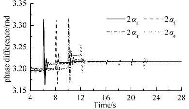
a)
b)
6. Conclusions
With the theoretical investigation and numeric analysis conducted above, conclusive remarks are presented as follows.
1) The average method of modified small parameters and modal analysis are employed to investigate problem of vibration isolation for synchronization of the four VMs with eight URs. In accordance with the general dynamic symmetry of the vibrating system with two URs, synchronization and stability criteria are deduced by the generalized Lyapunov equations, Lyapunov criterion, and the Routh-Hurwitz criterion.
2) The proposed system of vibration isolation can eliminate the dynamic forces that the vibrating system acts on the foundation, i.e., the two URs in one of the four VMs operate in the vicinity of and excite only the corresponding mass vibration in -direction and the IRF is at rest during the normal working process.
3) When power supply of one of two URs in the VMs switched off, the coupling characteristics of the system can transfer energy from the motors with power supply to that without power supply to extend the synchronization of the eight URs and its robust to the external disturbances. But the phase differences and the synchronous speed will stabilize new values. During the processes of one power supply cut off or disturbance, the phase differences between two URs in the same VM change violently and stabilize rapidly, while the phase differences between two of the four VMs vary slowly and stabilize gradually.
References
-
Acebrón J. A., Bonilla L. L., Perez Vicente C. J., et al. The Kuramoto model: a simple paradigm for synchronization phenomena. Reviews of Modern Physics, Vol. 77, 2009, p. 137-185.
-
Blekhman I. I. Synchronization in Science and Technology. ASME Press, New York, 1988.
-
Blekhman I. I. Synchronization of Dynamical System. Nauk, Moscow, 1971, (in Russian).
-
Blekhman I. I. Vibrational Mechanics. World Scientific, Singapore, 2000.
-
Blekhman I. I. Selected Topics in Vibrational Mechanics. World Scientific, Singapore, 2004.
-
Blekhman I. I., Yaroshevich N. P. Extension of the domain of applicability of the integral stability criterion (extremum property) in synchronization problems. Journal of Applied Mathematics and Mechanics, Vol. 68, 2004, p. 839-846.
-
Wen B. C., Fan J., Zhao C. Y., et al. Vibratory Synchronization and Controlled Synchronization in Engineering. Science Press, Beijing, 2009.
-
Wen B. C. Recent development of vibration utilization engineering. Frontiers of Mechanical Engineering, Vol. 3, Issue 1, 2008, p. 1-9.
-
Zhao C. Y., Zhang Y. M., Wen B. C. Synchronization and general dynamic symmetry of a vibrating system with two exciters rotating in opposite directions. Chinese Physics B, Vol. 19, Issue 3, 2010, p. 030301.
-
Zhao C. Y., Wang D. G., Zhang H., et al. Frequency capture of a vibrating system with two-motor drives rotating in the same direction. Chinese Journal of Applied Mechanics, Vol. 26, Issue 2, 2009, p. 283-287.
-
Zhao C. Y., Zhu H. T., Zhang Y. M., et al. Synchronization of two coupled exciters in a vibrating system of spatial motion. Acta Mechanica Sinica, Vol. 26, Issue 2, 2010, p. 477-493.
-
Zhao C. Y., Wen B. C., Zhang X. L. Synchronization of the four identical unbalanced rotors in a vibrating system of plane motion. Science China Technological Science, Vol. 53, Issue 2, 2010, p. 405-422.
-
Meirovitch L. Elements of Vibration Analysis. Second Edition, McGraw-Hill Inc., Singapore, 1986.
-
Graham Kelly S. Advanced Vibration Analysis. CRC Press, Taylor and Francis Group, 2007.
-
Li H., Liu D., Li Y., et al. Self-synchronous theory of a dual-motor driven vibrating mechanism without shimmy. Archive of Applied Mechanics, Vol. 85, 2015, p. 657-673.
-
Zhao C. Y., Zhao Q. B., He B., et al. Effect of dynamic parameters on the performance of a three-mass vibrating machine. Journal of Vibration and Shock, Vol. 34, Issue 12, 2015, p. 70-78.
-
Zhang X. L., Wen B. C., Zhao C. Y. Synchronization of three homodromy coupled exciters in a non-resonant vibrating system of plane motion. Acta Mechanica Sinica, Vol. 28, Issue 5, 2012, p. 1424-1435.
-
Ma Z. J., Liu Z. R., Zhang G. Generalized synchronization of discrete systems. Applied Mathematics and Mechanics, Vol. 28, Issue 5, 2007, p. 546-550.
-
Zhang X. H., Zhang Q. L. Control Theory and Applications of Nonlinear Differential Algebraic System. Science Press, Beijing, 2007.
-
Lu Q. S. Qualitative Methods and Bifurcations of Ordinary Different Equations. Press of Beijing University of Aeronautics and Astronautics, Beijing, 1989, (in Chinese).
-
Kapitanicl M., Lazarek M., Nielaczyztof M., et al. Synchronization extends the life time of the desired behavior of globally coupled systems. Scientific Reports, Vol. 4, 2014, p. 4391.
About this article

This work was supported by the National Natural Foundation of China (Grant No. 51375081), and Program of Innovative Team for Liaoning Province Department of Education (Grant No. LT2014006).
