Abstract
Functionally Graded Materials (FGMs) are regarded as one of the most promising candidates for future advanced composites in many engineering applications. They can be classified as advanced materials characterized by variation in properties as the dimension varies. Since fracture is a key failure mode of FGMs, successful application of these materials depends on the understanding of their fracture mechanics. In addition, the stresses and displacements caused by dynamic loading can greatly differ from those associated with the corresponding static loading. This research focuses on obtaining Dynamic Stress Intensity Factors (DSIFs) in FGMs using displacement extrapolation method, considering the effect of damping. ABAQUS finite element package is applied to calculate displacement fields in FGMs. Accordingly, a User Material subroutine (UMAT) is written for implementing the continuous variation of material properties, and Rayleigh damping in the numerical analyses. In this research, the variations in properties of FGMs are considered exponentially; and the obtained results are compared with those presented in the technical literature. Then, the effects of different damping ratios on the DSIFs are investigated. According to the obtained results, damping has a significant effect on the DSIFs in FGMs. Therefore, ignoring this issue causes considerable errors in the results.
1. Introduction
Recently, a new class of engineering materials, termed as “Functionally Graded Materials” (FGMs), has been developed primarily for use in high temperature applications [1]. FGMs are microscopically non-homogeneous composites that are usually made from a mixture of ceramics and metals. These materials are used in the design of many engineering structures, machine tools and so on [2, 3]. The gradual variation in material properties instead of sharp interfaces as in the case of multilayered systems significantly improves the mechanical and thermal characteristics of FGMs [4]. Fracture resistance constitutes the primary design criterion, and hence in the case of FGMs, it has led to the development of a special field of fracture mechanics devoted to the failure of this class of materials [5].
Either homogeneous or graded finite elements can be used for considering the material property gradient of FGMs. Graded elements consider the variations of material properties accurately, whereas homogeneous elements follow an approximate stepwise process for this purpose. In other words, their material properties are adapted with those of the center of graded elements. It is obvious that graded elements can better simulate the material gradient comparing with homogeneous elements. Therefore, they are preferably used in the numerical analysis of FGMs [6].
Stress Intensity factors (SIFs) are important fracture parameters for understanding dynamic fracture behavior of both homogeneous and non-homogeneous materials [6]. Different methods such as displacement-based techniques [7-9], standard and modified integral [10, 11] have been proposed for the assessment of SIFs. Dynamic Stress Intensity Factors (DSIFs) are well-known fracture parameters that can predict the dynamic behavior of a cracked body. An accurate evaluation of DSIFs is essential in fracture mechanics, because they can be applied to investigate crack initiation and propagation [6].
Many researchers have studied the dynamic behavior of cracked bodies by using different methods. Chen [12] studied a cracked rectangular strip subjected to step loading using Lagrangian finite difference method. He obtained DSIFs from the relation between DSIFs and stress fields in the vicinity of a crack tip. His study is the benchmark of more studies in the field of DSIFs. Aoki et al. [7] used the relationship between DSIFs and displacements to obtain DSIFs. Brickstad [8] used an explicit time scheme in a special finite element program to evaluate DSIFs. He calculated DSIFs by means of the relationship between crack opening displacement and SIF. Some studies have also been carried out on the dynamic crack propagation in FGMs by using near-tip displacement fields (e.g., [13-15]).
The effect of damping on dynamic behavior of FGMs has been rarely considered in the investigations [16, 17]. Moreover, no assessment has been conducted on the effect of damping on DSIFs in FGMs. Thus, in this study, the effect of damping, as an important factor in the dynamic behavior of materials, is particularly investigated for the evaluation of DSIFs in FGMs. For this purpose, considering different damping ratios, DSIFs in plane strain and plane stress FGM models are calculated using displacement extrapolation method [18].
2. Modeling and verification
In order to perform the numerical analysis of FGMs by using a finite element package, it should have the capability of modeling graded elements, or this capability should be added to the package by writing the neccesary codes. In this study, ABAQUS finite element package [19] is used for analyzing the considered problems. When using ABAQUS, it is possible to write a User Material (UMAT) subroutine to define the mechanical constitutive behavior of a material. In this regard, a UMAT subroutine is written in order to apply the continuous variration of material properties in the numerical analyses. This subroutine is written in such a way to provide the possibility of considering Rayleigh damping in the dynamic analysis [20]. The displacement fields in the vicinity of crack tip are obtained by using ABAQUS, and then, the DSIFs are calculated based on the following equations [18]:
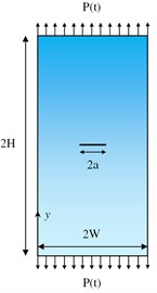
where and are displacement components in x and y directions; and are Mode I and II SIFs; is radial distance; is crack propagation angle with respect to initial crack; is shear modulus and is Poisson’s ratio. In order to investigate the effect of damping on DSIFs in FGMs, the calculation of these factors should be verified. For this purpose, the DSIFs ( and ) are calculated through Eqs. (1-4) for a plane strain plate with a center crack under dynamic loading in the vertical direction, considering different gradients of material properties. The obtained results are compared with those of the study performed by Song [6]. Fig. 1(a) shows the considered FGM plate of width 20 mm and height 40 mm, with a center crack of length 4.8 mm. The dynamic load (, is Heaviside step function), shown in Fig. 1(b), is applied to the both ends of the plate. Similar to the study performed by Song [6], modulus of elasticity () and density (), for the FGM plate, are assumed to vary exponentially in the axis direction (see Fig. 1(a)), as follows:
where and are modulus of elasticity and density of homogeneous material, which are equal to 199.992 GPa and 5000 kg/m3, respectively; is the material gradation parameter, which represents the gradient of material properties along the axis direction. The parameter is equal to 0 for a homogeneous material, and can have a positive or negative value for a FGM material. In this study, based on the study performed by Song [6], three values of 0, 0.05 and 0.1 are considered for . Poisson’s ratio () is assumed to be constant and equal to 0.3. It should be mentioned that the assumption of exponential variation for the FGM properties has also been used by many other researchers (e.g., [4, 6, 21-24]).
Fig. 1a) Considered FGM cracked plate, b) applied load vs. time (step function)
a)
b)
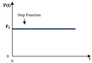
Fig. 2Finite element mesh of the FGM plate and mesh detail for the crack tip region
Second-order eight-node elements are used for finite element modeling. Fig. 2 illustrates the finite element mesh of the FGM plate. Regarding the stress singularity at the crack tip, the mesh size in the near-tip region is selected small enough to obtain acceptable results. The displacement extrapolation method [18] is used to evaluate the values of DSIFs at the crack tip. The UMAT subroutine is written in such a way that the modulus of elasticity in integration points is obtained based on Eq. (6). The variation of density for FGMs cannot be modeled in the UMAT subroutine. Therefore, density is defined as a function of an additional variable i.e., temperature. Hence, using a predefined field, the value of temperature in each node is assumed to be equal to the coordinate of the node.
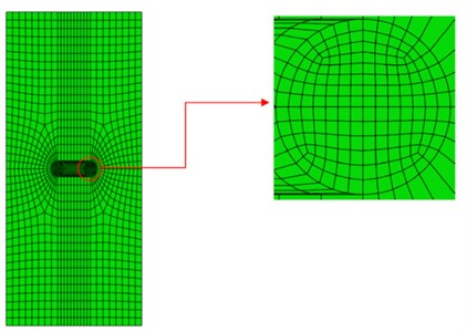
In the numerical simulation, the whole plate is modeled and tensile load is applied to its top and bottom edges in the -axis direction. The time histories of and , obtained considering different values for , are presented in Fig. 3 and compared with those of Song [6] ( and longitudinal wave speed of homogeneous material is 7.34 mm/μsec). Regarding the fact that the finite element meshes are not completely identical, the comparison confirms the accuracy of the obtained results. Therefore, it can be inferred that the method used in this study can calculate DSIFs in FGMs with appropriate accuracy.
Fig. 3Verification of DSIFs in the present study with the results from Song [6], for different material gradients along the y-axis direction
![Verification of DSIFs in the present study with the results from Song [6], for different material gradients along the y-axis direction](https://static-01.extrica.com/articles/16793/16793-img4.jpg)
a)
![Verification of DSIFs in the present study with the results from Song [6], for different material gradients along the y-axis direction](https://static-01.extrica.com/articles/16793/16793-img5.jpg)
b)
3. Rayleigh damping and its implementation for dynamic analysis of FGMs
Rayleigh damping is a general method for considering the effect of damping in direct-integration dynamic analysis. In this method, damping matrix is assumed to be proportional to a combination of mass and stiffness matrices, expressed as follows [20]:
where , and are the damping, mass and stiffness matrices, respectively; and and are the coefficients of mass and stiffness matrices, respectively, that can be calculated as follows:
where is damping ratio; and are the frequencies of two vibration modes the damping ratio of which is considered as ; is the frequency of the first mode with the highest effective modal mass; and is the frequency of a higher mode (a mode in which its cumulative effective mass ratio is higher than a certain value (e.g., 0.95)). Rayleigh damping can be used to consider the effect of damping in the dynamic analysis of FGMs. As previously mentioned, in this research, a UMAT subroutine is applied to consider the continuous variation of modulus of elasticity in FGMs. When using UMAT, stiffness proportional damping cannot be applied directly in the ABAQUS, and must be defined in the UMAT by the Jacobian and stress definitions [19]. It means that for considering the stiffness proportional damping, an additional stress caused by damping () must be defined in the UMAT subroutine, using factor, as follows:
where is the strain rate; and is the elasticity tensor. The stress is added to the stress caused by the constitutive equation at the integration point when dynamic equilibrium equations are formed, but it is not included in the stress output. For this purpose, a state variable is considered for each stress component in the UMAT subroutine. In this process, the value of stress component is saved as a state variable after updating the stress by the constitutive equation, and before adding the corsponding value to each of the stress components. This state variable is used as the stress output at the end of each step. After solving dynamic equilibrium equations by using the sum of the updated stress through constitutive equation and its corresponding value, the state variable saved in the previous step is substituted for its corresponding stress component at the beginning of the next step.
3.1. Verifying the implementation of Rayleigh damping in UMAT subroutine
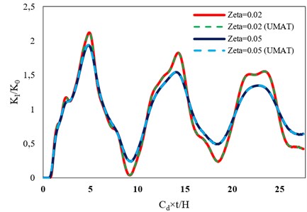
In order to make a finite element model with an elastic homogeneous material by applying ABAQUS, either elastic material option or UMAT can be used. When using the elastic material in ABAQUS, Rayleigh damping can be modeled directly, but when using a UMAT subroutine, the stiffness proportional part of Rayleigh damping should be written in the UMAT. If the results of these two methods are the same, then, it can be concluded that the code written in the UMAT subroutine properly considers the stiffness proportional part of Rayleigh damping. Accordingly, the plate shown in Fig. 1(a) is modeled using these two methods considering a homogeneous material (0), with different damping ratios, to evaluate its DSIFs. Table 1 presents the values of effective modal mass and cumulative effective mass ratio for the mentioned plate considering 15 modes. The frequencies of second and sixth modes are used in Eq. (9), to obtain the values of and , because this frequency range includes a significant portion of effective modal mass. Table 2 presents the values of and obtained to apply Rayleigh damping, by using the two selected frequencies, assuming damping ratios of 0.02 and 0.05. Fig. 4 shows the time historiers of normalized DSIF, , obtained for the plate shown in Fig. 1(a), assuming the two aforementioned methods of modeling stiffness proportional damping (through UMAT subroutine and direct modeling in ABAQUS). Based on the results shown in Fig. 4, the values of DSIF obtained from using UMAT subroutine for both damping ratios completely match with those of directly defining , as an input, in ABAQUS. It means that stiffness proportional damping can be precisely modeled using the UMAT subroutine. Therefore, this method can be used for applying stiffness proportional damping in FGMs.
Table 1Modal frequencies, effective modal masses, and cumulative effective mass ratios for the considered model
Mode No. | (rad/s) | Effective modal mass (kg) | Cumulative effective mass ratio |
1 | 6.283 | 4.51E-15 | 0.0000 |
2 | 12.566 | 3.15E-02 | 0.8700 |
3 | 18.850 | 1.62E-12 | 0.8700 |
4 | 25.133 | 5.75E-13 | 0.8700 |
5 | 31.416 | 2.13E-14 | 0.8700 |
6 | 37.699 | 3.41E-03 | 0.9642 |
7 | 43.982 | 9.82E-15 | 0.9642 |
8 | 50.265 | 3.15E-04 | 0.9729 |
9 | 56.549 | 4.84E-11 | 0.9729 |
10 | 62.832 | 1.95E-04 | 0.9783 |
11 | 69.115 | 5.39E-04 | 0.9932 |
12 | 75.398 | 2.45E-04 | 1.0000 |
13 | 81.681 | 2.99E-13 | 1.0000 |
14 | 87.965 | 5.18E-07 | 1.0000 |
15 | 94.248 | 1.10E-12 | 1.0000 |
Table 2Coefficients of mass and stiffness matrices obtained to apply Rayleigh damping
0.02 | 7536.876 | 4.098E-08 |
0.05 | 18842.189 | 1.024E-07 |
Fig. 4Comparison between the time histories of normalized DSIF, KI/K0, obtained for the plate with a center crack assuming two methods of modeling stiffness proportional damping
4. The effect of damping on DSIFs in FGMs
4.1. FGM plate with a center crack
In this section, the effect of damping on DSIFs in a FGM plate with a center crack, shown in Fig. 1(a), is investigated. The variations of modulus of elasticity and density, in the -axis direction, are assumed to be based on Eqs. (6) and (7), respectively. Figs. 5 and 6 show the time histories of normalized DSIFs for the considered plate in the homogeneous (0) and FGM (0.1) states, respectively, assuming damping ratios of 0, 0.02 and 0.05. According to these figures, damping has a significant effect on the DSIF; and this influence increases with the increase of the response duration.
Fig. 5Time histories of normalized DSIF in a homogeneous plate with a center crack assuming different damping ratios
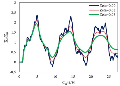
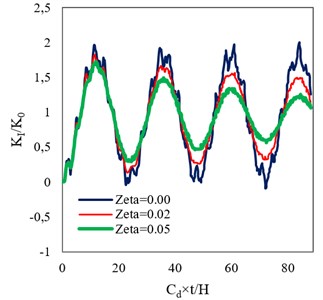
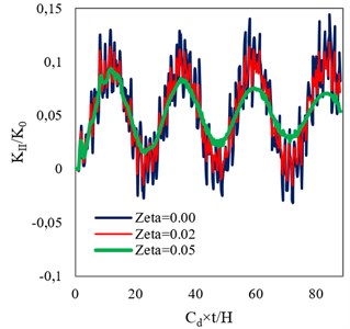
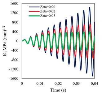
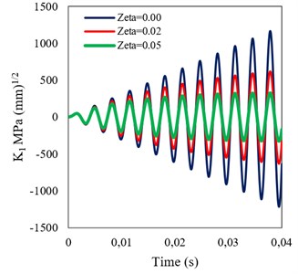
4.2. FGM beam with an edge crack
In this section, the effect of damping on DSIF in a FGM beam with an edge crack, shown in Fig. 7, is investigated. The length, width, and thickness of the beam are 1000, 160 and 1 mm, respectively, and it is modeled as a simply supported plane stress beam. An edge crack with a length of 40 mm is assumed in the middle span of the beam. The beam is subjected to two types of dynamic point loading, which are Heaviside step loading (, 5000 N), and sinusoidal loading (, 500 N and is the first mode period of the beam). As shown in Fig. 7, each of these dynamic loadings is applied at the middle of the beam. The variations of modulus of elasticity and density for the beam are considered in the -axis direction.
Fig. 6Time histories of normalized DSIFs in a FGM plate with a center crack assuming β= 0.1 and different damping ratios
a)
b)
Fig. 7Simply supported FGM beam with an edge crack
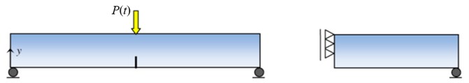
Fig. 8Mesh configuration for the FGM beam, and mesh detail for the crack tip region
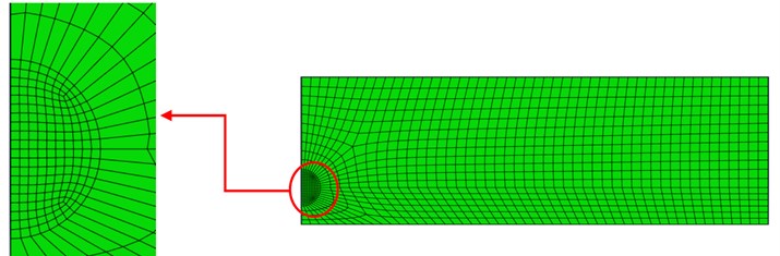
Due to the symmetry of the studied problem, half of the beam is modeled in ABAQUS, and therefore, the load applied to this part is halved as well. Assuming 0.005, the variations of and for the FGM beam are based on Eqs. (6) and (7), respectively. and are assumed equal to 200 GPa and 7850 kg/m3, respectively, and Poisson’s ratio is assumed to be constant (0.3). The finite element mesh of the model is shown in Fig. 8. It can be seen that in the vicinity of the crack tip the mesh size is considered to be smaller than that of the other regions. Fig. 9 illustrates typical stress distributions in the near crack region of the FGM beam with damping ratio of 0.05 under sinusoidal loading at time 0.005 s. It can be seen that maximum stress has occurred at the crack tip.
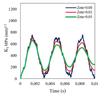
Figs. 10 and 11 present the time histories of DSIF for the studied beam, in the homogeneous (0.0) and FGM (0.005) states (assuming three damping ratios of 0, 0.02 and 0.05) under step and sinusoidal loadings, respectively. It can be seen that, under each of the dynamic loadings, damping has a significant effect on the DSIFs obtained assuming the both material states. Furthermore, simultaneous increasing of stiffness and density in the FGM beam causes the reduction of DSIF compared with that of the homogeneous one.
Fig. 9Stress distributions in the near crack region of the FGM beam
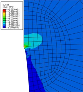
Fig. 10Time histories of DSIF obtained assuming different damping ratios for a) homogeneous, and b) FGM (β= 0.005) beams under step loading
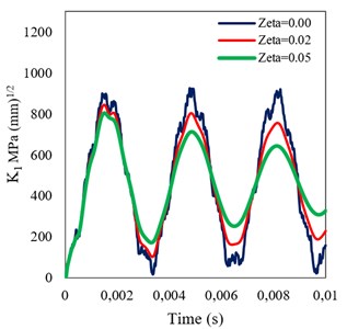
a)
b)
Fig. 11Time histories of DSIF obtained assuming different damping ratios for a) homogeneous, and b) FGM (β= 0.005) beams under sinusoidal loading
5. Conclusions
In this study, the effect of damping on DSIFs in FGMs was investigated. ABAQUS finite element package was used to perform dynamic analyses, and a UMAT subroutine was written to apply the continuous exponential variation of modulus of elasticity. Temperature was used as an additional variable to consider the variation of density. In the case of using UMAT subroutine for modeling FGMs, ABAQUS is not able to apply the stiffness proportional part of Rayleigh damping directly. Therefore, the UMAT was written in such a way to provide the stiffness proportional damping in the dynamic analysis. It should be mentioned that mass proportional damping can be applied by the ABAQUS directly. The UMAT was verified to consider the stiffness proportional damping correctly. Then, the effects of different damping ratios on DSIFs in a plane strain plate with a center crack, and also a plane stress beam with an edge crack, assuming homogeneous and FGM properties, were investigated. The obtained results showed that damping has a significant effect on DSIFs in the both first and second modes of crack opening. Briefly, it can be concluded that if the time duration of response is not low in comparison with the fundamental period of the model, ignoring the effect of damping leads to considerable errors in the prediction of DSIFs.
References
-
Niino M., Hirai T., Watanabe R. The functionally gradient materials. Journal of the Japan Society for Composite Materials, Vol. 13, 1, p. 1987-257.
-
Fallah A., Aghdam M. M. Thermo-mechanical buckling and nonlinear free vibration analysis of functionally graded beams on nonlinear elastic foundation. Composites Part B: Engineering, Vol. 43, Issue 3, 2012, p. 1523-1530.
-
Liu Y., Shu D. W. Free vibration analysis of exponential functionally graded beams with a single delamination. Composites Part B: Engineering, Vol. 59, 2014, p. 166-172.
-
Rousseau C. E., Tippur H. V. Evaluation of crack tip fields and stress intensity factors in functionally graded elastic materials: cracks parallel to elastic gradient. International Journal of Fracture, Vol. 114, Issue 1, 2002, p. 87-112.
-
Martínez-Pañeda E., Gallego R. Numerical analysis of quasi-static fracture in functionally graded materials. International Journal of Mechanics and Materials in Design, Vol. 11, Issue 4, 2015, p. 405-424.
-
Song S. H. Dynamic Stress Intensity Factors for Homogeneous and Non-Homogeneous Materials Using the Interaction Integral Method. Master Thesis, Department of Civil and Environmental Engineering, University of Illinois at Urbana-Champaign, 2003.
-
Aoki S. H., Kishimoto K., Kondo H., Sakata M. Elastodynamic analysis of crack by finite element method using singular element. International Journal of Fracture, Vol. 14, Issue 1, 1978, p. 59-68.
-
Brickstad B. A FEM analysis of crack arrest experiments. International Journal of Fracture, Vol. 21, Issue 3, 1983, p. 177-194.
-
Lim I. L., Johnston I. W., Choi S. K. Comparison between various displacement-based stress intensity factor computation techniques. International Journal of Fracture, Vol. 58, Issue 3, 1992, p. 193-210.
-
Enderlein M., Ricoeur A., Kuna M. Comparison of finite element techniques for 2D and 3D crack analysis under impact loading. International Journal of Solids and Structures, Vol. 40, Issue 13, 2003, p. 3425-3437.
-
Chang-chun W., Peixiang H., Ziran L. Extension of J integral to dynamic fracture of functional graded material and numerical analysis. Computers and Structures. Vol. 80, Issue 5, 2002, p. 411-416.
-
Chen Y. M. Numerical computation of dynamic stress intensity factors by a Lagrangian finite-difference method (the HEMP code). Engineering Fracture Mechanics, Vol. 7, Issue 4, 1975, p. 653-660.
-
Jain N., Shukla A. Displacements, strains and stresses associated with propagating cracks in materials with continuously varying properties. Acta Mechanica, Vol. 171, Issue 1, 2004, p. 75-103.
-
Chalivendra V. B., Shukla A., Parameswaran V. Dynamic out of plane displacement fields for an inclined crack in graded materials. Journal of Elasticity, Vol. 69, Issue 1, 2002, p. 99-119.
-
Parameswaran V., Shukla A. Near-tip out of plane displacement fields for dynamic crack propagation in functionally graded materials. Mechanics Research Communications, Vol. 29, Issue 5, 2002, p. 397-405.
-
He X. Q., Ng T. Y., Sivashanker S., Liew K. M. Active control of FGM plates with integrated piezoelectric sensors and actuators. International Journal of Solids and Structures, Vol. 38, Issue 9, 2001, p. 1641-1655.
-
Aksoylar C., Ömercikoğlu A., Mecitoğlu Z., Omurtag M. H. Nonlinear transient analysis of FGM and FML plates under blast loads by experimental and mixed FE methods. Composite Structures, Vol. 94, Issue 2, 2012, p. 731-744.
-
Mohammadi S. Extended Finite Element Method: for Fracture Analysis of Structures. John Wiley and Sons, 2008.
-
ABAQUS User’s Manual, Version 6.9. Dassault Systemes, 2009.
-
Clough R. W., Penzien J. Dynamics of Structures. Computers and Structures, USA, 2003.
-
Erdogan F., Wu B. H. The surface crack problem for a plate with functionally graded properties. Journal of Applied Mechanics, Vol. 64, Issue 3, 1997, p. 449-456.
-
Jeong-Ho K., Paulino G. H. Isoparametric graded finite elements for nonhomogeneous isotropic and orthotropic materials. Journal of Applied Mechanics, Vol. 69, Issue 4, 2002, p. 502-514.
-
Parameswaran V., Shukla A. Crack-tip stress fields for dynamic fracture in functionally gradient materials. Mechanics of Materials, Vol. 31, Issue 9, 1999, p. 579-596.
-
Ekhlakov A. V., Khay O. M., Zhang C., Sladek J., Sladek V. A BDEM for transient thermoelastic crack problems in functionally graded materials under thermal shock. Computational Materials Science, Vol. 57, 2012, p. 30-37.
About this article

