Abstract
This paper presents a method for decreasing sound radiation from vibrating plates. The method uses Functionally Graded Materials (FGM) for building the plates instead of isotropic material. The graded pattern of material composition is characterized within the in-plane directions based on a two-dimensional trigonometric law. In the proposed method, the finite element method (FEM) is utilized for estimating the dynamic response of the plates. Then, the Lumped Parameter Model (LPM) is used for calculating sound radiation power. A genetic algorithm is applied as an optimization tool for determining the best distribution of the FGM. The efficacy of the proposed method is demonstrated by three design problems; minimizing the radiated sound from vibrating FGM plate at a particular excitation frequency, over a frequency band, and at a particular natural frequency. The design problems show that a considerable decrease of sound power can be accomplished with the optimal design of FGM plates in comparison with the isotropic plates.
Highlights
- A method for decreasing sound radiation from vibrating plates is presented.
- The method uses Functionally Graded Materials (FGM) for building the plates instead of isotropic material.
- The graded pattern of material composition is characterized within the in-plane directions based on a two-dimensional trigonometric law.
- The finite element method (FEM) is utilized for estimating the dynamic response of the plates. Then, the Lumped Parameter Model (LPM) is used for calculating sound radiation power.
- A genetic algorithm is applied as an optimization tool for determining the best distribution of the FGM.
- The suggested material distribution law properly provides a flexible description of material volume fraction profiles which gives a powerful tool for designing quiet plate structures.
1. Introduction
In modern structural and machine design, noise reduction from vibrating element is one of the common challenges of engineers. Some of the most important sound radiation elements include vibrating plate structures. Sound radiation minimization is typically performed via passive methods by adding auxiliary elements to the original structure like masses [1-3], adding stiffeners [4-7], local thickness distribution [8-11], modifying boundary supports [12-15], shape modification [16-19], and/or using material tailoring [20].
Material tailoring to realize a reduction in sound radiation, at a single frequency, was studied first by Naghshineh and Koopmann [20]. They enforce the structure to vibrate as a weak radiator at a specific frequency. They divided the structure into segments. The material properties of each segment were assumed to be independent of other segments, i.e., the Young’s modulus and the material density are physically unrelated and continuity conditions are not enforced. A distinguishing feature of this paper is that, material tailoring is implemented using FGM for minimizing the sound radiation from vibrating plates.
FGMs are new composites typically made of at least two materials with continuous changing of materials’ composition within the volume. The continuous variation of composition results in a consistent and smooth variation of material properties such as Young’s modulus and density. The idea of FGMs initially rose in the 1980s for engineering applications which were necessary to endure in situations with a high-temperature gradient such as thermal barriers. Due to their superior characteristics, the FGMs are widely used in aerospace, biomedical, defense, energy, and optoelectronic applications [21].
A large and growing body of the literature has investigated the vibration of FGM plates. Previous studies have examined the dynamics of FGM plates [22, 23]. Forced vibration of FGM plates was considered by different studies. For example, Yang and Shen [24] investigated the forced vibration of FGM plates which are exposed to diverse sorts of loadings such as pulse, or harmonic, or exponential with respect to time. The plates were initially stressed and rested on an elastic foundation. The equations of motion were obtained based on classical plate theory, then the Galerkin methodology was employed to study the dynamic response. Yang and Shen [25] examined the forced vibration of FGM plates which were subjected to initial stress in a thermal medium. They used the Galerkin and modal superposition methods to determine the behavior of the vibrating plates. Qian et al. [26] modeled FGM plate exposed to forces and transient thermal loads using the higher-order shear deformation theory. The dynamic responses were attained using the meshless Petrove-Galerkin approach. Vel and Batra [27] presented an exact solution for the forced vibration of FGM thick plates exposed to thermal loads. The equations of motion were transformed from PDEs to a group of coupled ODEs by utilizing displacement functions identically satisfying the boundary conditions. Huang and Shen [28] modeled stressed FGM plates, exposed to mechanical and thermal loads, using Reddy’s third-order shear deformation. Next, a perturbation technique was used to study the dynamic response. Using state-space and one-dimensional differential quadrature methods, Nie and Zhong [29] investigated forced vibration of FGM circular plates. They found that this semi-analytical method is computationally efficient. Allahverdizadeh et al. [30] presented a semi-analytical method to analyze the axisymmetric forced vibration of a circular FGM plate. The solutions were obtained using the Kantorovich time averaging procedure. Based on Reddy’s third-order shear deformation theory and Hamilton’s principle, Hao et al. [31] derived the equations of motion of FGM plates. The Galerkin strategy was employed to change over the equations of motion into a nonlinear two degree of freedom system. Fakhari et al. [32] utilized FEM to analyze the dynamic responses of FGM plates. The plate was bonded, at the surface, by piezoelectric layers and exposed to electrical and mechanical loadings. Shen and Wang [33] investigated the forced vibration of FGM plate supported by Winkler-Pasternak elastic base. The equations of motion were derived utilizing a higher-order shear deformation theory. Prakash et al. [34] investigated the flutter behavior of FGM plates subjected to supersonic airflow using FEM. The effects of Mach number and aerodynamic loads on the FGM plate vibration were considered. Most commonly, researchers have studied the vibration of FGM plates when material compositions vary through the thickness only by power or exponential laws [24-34]. Alshabatat et al. [35] investigated the designing of in-plane FGM plates for optimum fundamental frequencies and minimum kinetic energy level at a specific excitation frequency. The FGM constituents were varied throughout the two in-plane directions of the plate. The free and forced vibration characteristics were assessed using the FEM.
The sound radiation from vibrating FGM plates has been studied infrequently. Kumar et al. [36] examined the vibroacoustic behavior of FGM elliptic plate exposed to thermal and mechanical loadings. The vibration and acoustic responses were evaluated using FEM and the BEM, respectively. Chandra et al. [37] investigated the vibroacoustic and transmission loss characteristics of FGM plate analytically. The governing equations were formulated using Hamilton’s approach, and then the solution was derived using Navier strategy. The sound radiation was calculated based on the Rayleigh integral. Both Refs. [36, 37] assumed that the phases of FGM vary according to a power law through plate thickness. They investigated the effect of the power index on the radiated sound power. Chandra et al. [38] studied the vibroacoustic response of sandwich plates with functionally graded core and isotropic face sheets using the same approach as Chandra et al. [37]. Similarly, the material properties of the core are assumed to vary according to a power low distribution through plate thickness.
To the best of authors’ knowledge, minimizing sound radiation from vibrating plates, using FGM, has not been attempted. This paper investigates the potential usefulness of using FGM instead of isotropic materials for minimizing the radiated sound from excited plates. As mentioned above, some researchers [36-38] have studied the vibroacoustic behavior of FGMs plates with material variation through thickness direction only. This paper presents a two-dimensional trignometric law, with six design variables, for describing the material variation through the in-plane directions of the FGM plate that gives engineers a powerful tool for design optimization. The proposed method for minimizing the radiated sound from vibrating plates using FGM couples the finite element method (for computing the vibration response of the vibrating FGM plates), Lumped Parameter Model [39] for evaluating the sound power, and a Genetic Algorithm (GA) as an optimization tool. The efficacy of the proposed technique is illustrated by three design problems. In the first problem, the sound radiation from a vibrating FGM plate at a particular excitation frequency is minimized. The second design problem minimizes the sound radiation from a vibrating FGM plate over a frequency band. The third design problem minimizes the sound radiation from a vibrating FGM plate of a particular natural frequency.
2. Theoretical background
2.1. Effective properties of FGM plate
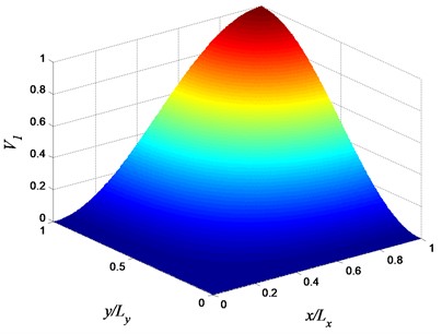
The plates under consideration are rectangular with length , width , and thickness (, , and ). It is constructed from a blend of two materials. This work suggests that the volume fractions of the constituents change gradually throughout the in-plane directions according to six-parameter trigonometric law:
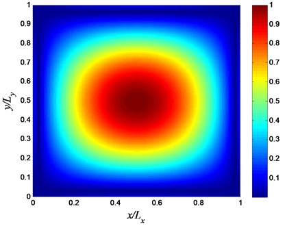
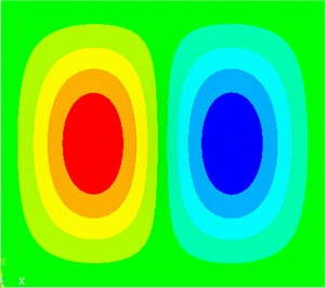
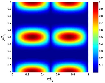
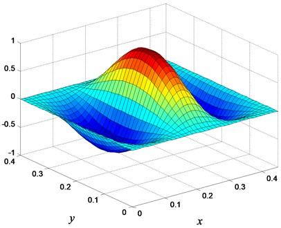
where is the volume fraction of the first constituent, and the volume fraction of the second constituent is . The volume fractions and have ranges between zero and one (i.e., , and ). The parameters , , , , and are design variables which control the volume fraction through the FGM plate in-plane directions. The values of these parameters must be chosen so that . Eq. (1) represents an expansion of the trigonometric distribution law proposed in Alshabatat and Naghshineh [40] with application to vibrating beams. Examples of the volume fraction profiles based on Eq. (1) are shown in Figs. 1-2. As can be seen from Figs. 1 and 2, Eq. (1) provides a flexible description of material volume fraction distribution which gives a powerful tool for design optimization as will be shown later in this paper. The GA will be used to determine the six-parameters in Eq. (1) that yields optimal FGM profiles.
Fig. 1Volume fraction variation of constituent 1 (αx=0, αy=βy=1, and φy=π/2)
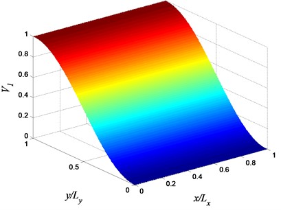
Fig. 2Volume fraction variation of constituent 1 (αx=αy=βx=βy=1, and φx=φy=π/2)
The local material properties of the FGM are estimated using the Mori-Tanaka method [41]. The effective local bulk modulus and effective local shear modulus can be calculated by:
where:
Subscripts 1 and 2, in Eqs. (2-4), refer to constituent 1 and constituent 2, respectively. The effective Young’s modulus and Poisson's ratio, as functions of - and -coordinates, can be estimated by:
The density can be estimated via the rule of mixture:
where and are the densities of constituent 1 and constituent 2, respectively.
2.2. Structural and acoustic analysis
The FEM is utilized herein in computing the response of the vibrating FGM plates. Every element consists of four nodes, and every node has six degrees of freedom (i.e., three translational and three rotational degrees of freedom). Each finite element was modeled as a homogeneous material with properties assigned according to the FGM effective properties at its centroid. The size of the elements is small enough in comparison with the acoustic wave length. The velocity vector of the vibrating FGM plate is evaluated by superposition of the normal modes. The velocity vector due to the nodal excitation force at a frequency is:
where , , , and are the mass-normalized eigenvector, natural frequency, and loss factor corresponding to the th mode, respectively, and the total number of modes considered in the summation is .
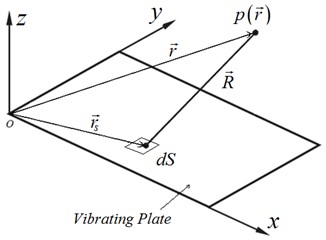
The plate under consideration is placed in an infinite rigid baffle and surrounded by air and it vibrates in the out of plane motion. It is assumed that the acoustic medium (fluid) has a low density, such as air, to neglect the interaction between the fluid and the structure (i.e., the fluid is assumed not to exert any load on the structure). The sound pressure due to plate normal surface velocity can be calculated using Rayleigh integral (see Fig. 3):
where is the density of air, is the normal velocity of the elemental surface , and Green’s function is given by:
where is the wave number, and .
Fig. 3Coordinates of a baffled plate radiator
The average sound power can be calculated by integrating the sound intensity over plate surface as:
where is the conjugate complex of . The Lumped Parameter Model (LPM) [39] is employed herein to estimate the sound power of vibrating FGM plates. In the LPM, the radiated surface is divided into elements which are small in comparison with the acoustic wavelength, and assuming the elements vibrate as pistons with uniform normal velocities. Therefore, the average sound pressure over any element can be described by the elemental volume velocity. The sound power based on LPM is given by:
where and are the volume velocity of elements and , respectively, is the number of elements, and is the surface acoustic resistance which is given by:
where is the speed of sound in air, and is the imaginary component of Green’s function and is given by:
where is the center distance between the elements and . The radiated sound is described in shape of sound power level as , where is the reference sound power which equals 10-12 Watt.
3. Design examples
In this section, we look at the minimization of radiated sound power from vibrating plates using FGM instead of isotropic materials. In the following numerical examples, the FGM plates are made out of steel and aluminum with properties summarized in Table 1. The selection of these constituents is only for the exhibition of the idea in our case. The fabrication issues of this FGM are considered beyond the scope of this paper.
Table 1Material properties of FGM constituents
Property | Constituent 1 (Steel) | Constituent 2 (Aluminum) |
(GPa) | 200 | 69.3 |
(kg/m3) | 7800 | 2680 |
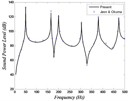
The validity of the sound power calculations is verified by a comparison between the results of our algorithm with results available in [17] for isotropic plate. The plate under consideration is aluminum rectangular plate clamped at all edges and has length 0.45 m, width 0.40 m, and thickness 1 mm. The plate is placed in an infinite baffle and vibrates in air. The damping factor is assumed to be 0.001. The plate is exposed to a unit force at its center with a frequency range 10-500 Hz. It is divided into 45×40 finite elements and 1886 nodes. The sound power of the vibrating plate is displayed in Fig. 4. As shown there’s good agreement between the present results and those of Jeon and Okuma [17]. Our simulation is based on LPM, while Jeon and Okuma [17] obtained the sound power by integrating the mean square sound pressure over 13 perception points distributed uniformly in a hemisphere surrounding the baffled plate.
Fig. 4Sound power level versus frequency for the validation study
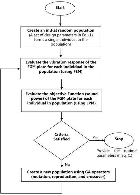
To show the efficiency of using FGMs rather than isotropic materials in designing plates with low sound radiation, three optimal design examples are presented. The first example involves minimizing the sound radiation from a FGM plate subjected to a single frequency excitation, the second example deals with minimizing the sound power over a frequency band, and the third example studies minimizing the sound power at a particular natural frequency. The optimal design of the FGM plate is based on the optimization of material distribution throughout plate area (i.e., the optimization of material distribution is achieved by optimizing the volume fractions of the material constituents). In all the optimization examples, a Genetic Algorithm (GA) is used for finding the volume fractions of material constituents which provide the optimal objective functions. The GA is a stochastic optimization method that is based on the concept of biological evolution. The GA starts its search with a set of individuals (called a population) forming the first generation or iteration. A set of six design parameters in Eq. (1) forms a single individual. The objective function or fitness function is evaluated for each individual. The individuals with good objective functions are used to generate a new set of individuals by using three basic operators: reproduction, crossover and mutation. A new set of individuals forms the second generation or iteration. The algorithm continues over many generations until a stopping criterion is met such as a time limit, reaching a specified maximum number of generations, or the change in fitness function between generations is smaller than a specified tolerance [42]. In this study, the population size for each generation is chosen to be 100, and the GA program will stop when the change of the sound power level is less than 10-3. The design process is depicted in the flow chart shown in Fig. 5.
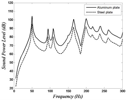
The FGM plates under consideration are similar in dimensions and boundary conditions to the plate in the validation study, however, the point force is positioned at a location diagonally halfway between the center and the corner of the plates ( and ). The place of the excitation force is chosen in order to energize every one of the modes in the frequency band under consideration. For all the modes, the loss factor is assumed constant and equals to 0.01. Fig. 6 shows the sound power versus frequency for steel and aluminum plates. The crests in this plot are the sound power level at plate’s first few natural frequencies.
Fig. 5Flow chart of design strategy
3.1. Sound minimization at a single frequency excitation
In this design example, FGM plate is designed to minimize the radiated sound due to vibration at a single frequency. As such we chose to focus on reduction of sound power at a frequency that was coincident with the first natural frequency of the homogeneous plate. Our goal was only to reduce the sound power level at this frequency. Any shift in the natural frequency of the plate was achieved as a consequence of reduction of sound power at this single frequency.
Fig. 6Sound power level versus frequency of the isotropic plates
The optimal design of the FGM plate depends on the proper distribution of the constituents throughout in-plane directions. The design variables are , , , , and in Eq. (1). The optimization problem is defined as:
Minimize: .
Subject to:
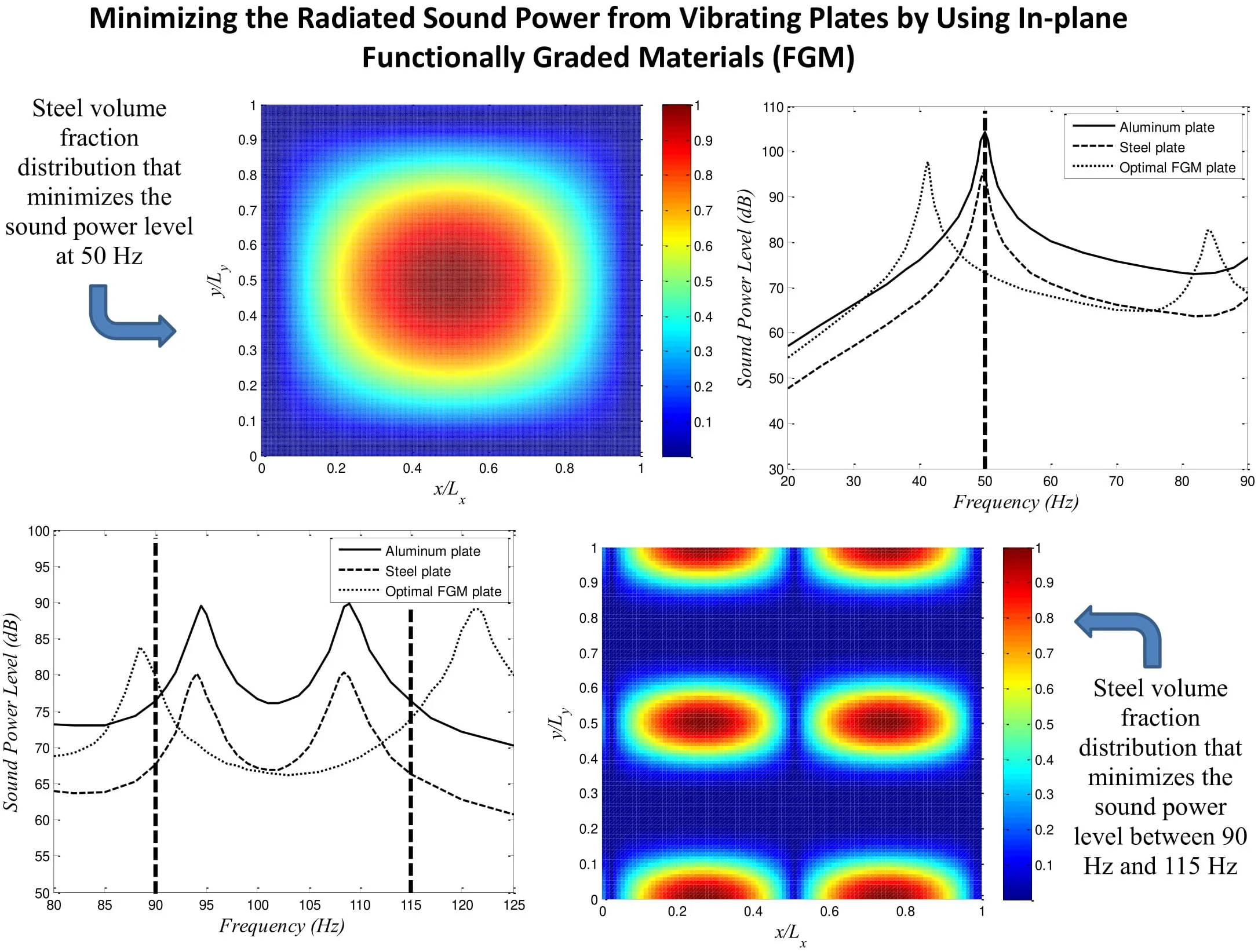
where , . In this article, the boundaries of the design variables are selected so that (i.e., and ). The GA is used to find the optimal design variables which provide the minimum sound radiation at 50 Hz frequency. At this frequency, the steel and aluminum plates have high sound power; 95 dB and 104.4 dB for steel and aluminum plates, respectively. The design strategy is shown in Fig. 5. The sound power level versus frequency curve for isotropic plates and optimal FGM plate are shown in Fig. 7.
Fig. 7Sound power level versus frequency of the isotropic plates and the optimal FGM plate at 50 Hz
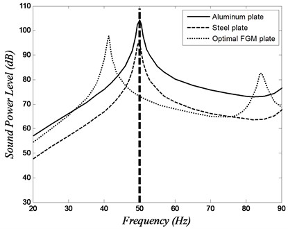
The design parameters that minimize the sound power at 50 Hz are listed in Table 2 (case 1), and corresponding steel volume fraction distribution is shown in Fig. 8. The sound power level of the optimal FGM plate at 50 Hz is 73.1 dB which is 21.9 dB and 31.3 dB less than the sound power level of steel and aluminum plates, respectively. Fig. 7 shows that the main consequence of the reduction of sound power level at 50 Hz is the shifting of the first natural frequency downward away from the frequency of interest. Note that the shift in the natural frequency was not the main target of this minimization but was a consequence of the re-distribution of the materials within the plate. Fig. 8 shows that placing heavy material (like steel) at the region of large modal displacement reduces the fundamental frequency significantly.
Fig. 8Steel volume fraction distribution that minimizes the sound power level at 50 Hz
3.2. Sound minimization over a frequency band
In this example problem, we demonstrate the efficiency of designing FGM plate for minimizing sound radiation over a frequency band. The average sound power over a band of frequencies can be estimated by:
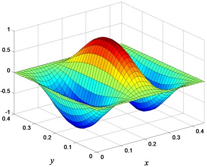
where is the number of frequencies under consideration between and , and is the sound power at the th frequency. The plate under consideration is similar to the one in the previous example. In order to reduce the computational cost of sound power in a relatively large frequency band, a small frequency band has been selected. This example is similar to the preceding example, however, with minimizing the average sound power between 90 Hz and 115 Hz, rather than sound power minimization at a single frequency. As shown in Fig. 6, this frequency range contains two natural frequencies for the isotropic plates. These are the second (2×1) and the third (1×2) modes as depicted in Fig. 9.
The sound power levels versus frequency for isotropic plates and optimal FGM plate are shown in Fig. 10. The average sound power of the steel plate is 75.2 dB, and the average sound power of the aluminum plate is 84.3 dB. The optimal design parameters which minimize the sound power level between 90 Hz and 115 Hz are listed in Table 2 (case 2), and corresponding steel volume fraction distribution appears in Fig. 11. The average sound power level of the optimal FGM plate is 71.2 dB which is 4 dB and 13.1 dB less than the average sound power level of steel and aluminum plates, respectively. Fig. 11 shows the optimal volume fraction distribution.
Fig. 9Illustration of the mode shapes of the plate: a) second mode, b) third mode
a) (2×1) mode – 88.5 Hz
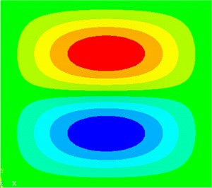
b) (1×2) mode – 121.2 Hz
Fig. 10Sound power level versus frequency of the isotropic plates and the optimal FGM plate over a frequency band
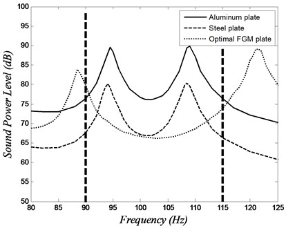
Fig. 11Steel volume fraction distribution that minimizes the sound power level between 90 Hz and 115 Hz
At this point, we can make several observations. First, we note that the second and the third natural frequencies of the FGM plate (result of the optimization process) have moved out of the frequency range of interest. This yields a lower average sound power level over the frequency band of interest. Second, we note that the peak sound power levels of the FGM plate at the second and third modes are higher than the corresponding values for the steel plate. These values are lower than the corresponding values of the aluminum plate. This is understandable since the FGM plate is a combination of steel and aluminum and has a mass that is lower than the steel plate but higher than the aluminum plate.
In order to understand the reason for the change in frequency of the second natural modes, we need to pay attention to the plate mode shapes (Fig. 9) and the distribution of the materials in the FGM plate (Fig. 11). Fig. 11 shows a material distribution that lowers the second plate mode by adding mass along the horizontal centerline of the plate and its two edges (steel is depicted in red). The added mass along the horizontal centerline coincides with the max deflections of the second mode which then lowers natural frequency for the (2×1) mode.
Similar comparison can be made in order to explain why the natural frequency of the third mode has increased. The added mass falls along the nodal lines of the (1×2) mode. The areas of max deflection in the third mode coincide with the areas of lower mass (blue colors). Thus, the natural frequency of the third mode is increased.
3.3. Sound minimization at a specific natural frequency
Dealing once again with the previously described vibrating clamped plate, we want to minimize the sound radiation at the fifth natural frequency (3×1 mode) by using FGM instead of isotropic materials. The sound power levels for the steel plate and the aluminum plate at the fifth natural frequencies are 91.4 dB and 100.6 dB, respectively. The sound power levels versus frequency for steel, aluminum, and FGM optimal plate at the 5th natural frequency are shown in Fig. 12. The optimal parameters which minimize the sound power at fifth natural frequency are listed in Table 2 (case 3). Fig. 13 shows the steel volume fraction distribution of the presented FGM plate. The radiated sound power from the presented FGM plate, at the 5th natural frequency, has a level of 71.4 dB which is 20.0 dB and 29.2 dB lower than those of steel and aluminum plates, respectively.
Fig. 12Sound power level versus frequency of the isotropic plates and the optimal FGM plate at the 5th natural frequency
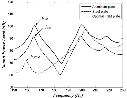
Table 2The sound power levels of optimal FGM plates and isotropic plates
Sound power level (dB) | Optimal FGM parameters | ||||||||
Steel | Aluminum | FGM | |||||||
Case 1 | 95.0 | 104.4 | 73.1 | 0.423 | 0.535 | 2.106 | 2.133 | 1.404 | 1.403 |
Case 2 | 75.2 | 84.3 | 71.2 | 0.344 | 1.921 | 4.136 | 4.009 | 1.325 | –1.554 |
Case 3 | 91.4 | 100.6 | 71.4 | 2.132 | 0 | 3.036 | any | –3.081 | any |
To study the difference in mode shapes between the isotropic and FGM plates, the modal assurance criterion (MAC) is used. The MAC value is computed by:
where and are the mode shape vectors of the isotropic and FGM plate, respectively. A MAC value of unity demonstrates that both mode shapes are the same. Changing the mode shapes clearly modifies the attributes of vibrations and influences the sound radiation from the plate. In this example, the MAC value between the isotropic plate and the optimal FGM plate is 0.865. This value indicates that the changes in the mode shape play a critical role in minimizing the sound radiation. The mode shapes of the isotropic plates and optimal FGM plate are shown in Fig. 14. A comparison of this mode shape with the weak radiator mode shapes given by Naghshineh and Koopmann [20] shows a strong resemblance. This indicates that the reduction in radiated sound power was the result of altering the plate mode shape to that of a weak radiator mode.
Fig. 13Steel volume fraction distribution that minimizes the sound power level at the 5th natural frequency
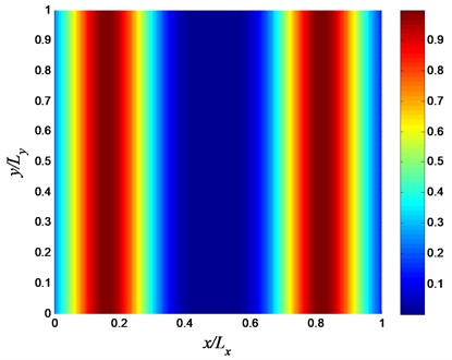
Fig. 14The 5th mode shape of a) isotropic plate, and b) optimal FGM plate
a)
b)
4. Conclusions
The main goal of the current study was to show the potential of using functionally graded material (FGM) for reducing the radiated sound from vibrating plates. The numerical results demonstrate the efficiency of using FGM for minimizing sound radiation. The FGM properties vary through the in-plane directions. A six-parameter law was used to describe the material volume fraction distribution and the material properties, at any point in the FGM plate, were evaluated utilizing Mori-Tanaka methodology. The design method relies on the finite element method for calculating the plate vibration responses, lumped parameter model for calculating the sound power, and a Genetic Algorithm as an optimizer.
Three numerical examples were presented for designing optimal FGM plates. The first example investigated the design of FGM plate to minimize the radiated sound at a particular excitation frequency. In the second example, the average radiated sound from a vibrating FGM plate was minimized over a narrow frequency band containing two modes. The sound power level at a particular natural frequency was minimized in the third example. The numerical examples suggest that the variation of the material properties, throughout the in-plane directions of a plate, plays an important part in control its vibroacoustic characteristics. The suggested material distribution law properly provides a flexible description of material volume fraction profiles which gives a powerful tool for designing quiet plate structures. The current investigation was limited to minimize sound radiation from vibrating plates. Further research is required to account for stress failure analysis as well as manufacturing limitations.
References
-
St. Pierre R., Koopmann G. A design method for minimizing the sound power radiated from plates by adding optimally sized, discrete masses. Transactions of the ASME, Vol. 117, 1995, p. 243-251.
-
Wodtke H. W., Koopmann G. Quieting plate modes with optimally sized point masses – a volume velocity approach. Proceedings of ASME 15th biennial conference on mechanical vibration and noise, Vol. 84, Issue 3, 1995, p. 647-654.
-
Li S., Li X. The effects of distributed masses on acoustic radiation behavior of plates. Applied Acoustics, Vol. 69, Issue 3, 2008, p. 272-279.
-
Fahy F., Gardonio P. Sound and Structural Vibration. Second Edition, Academic Press, New York, 2006
-
Moyne S., Tébec J. L., Kraemer J. Source effect of ribs in sound radiation of stiffened plates. Acta Acustica united with Acustica, Vol. 86, Issue 3, 2000, p. 457-464.
-
Moyne S., Tébec J. L., Tawfiq I. Acoustical influence of stiffeners on acoustic radiation of plates. Mechanical Systems and Signal Processing, Vol. 19, 2005, p. 195-212.
-
Xin F., Lu T. Sound radiation of parallelly stiffened plates under convicted harmonic pressure excitation. Science China Technological Sciences, Vol. 55, 2, p. 496-500.
-
Lamancusa J. S. Numerical optimization techniques for structural-acoustic design of rectangular panels. Computers and Structures, Vol. 48, Issue 4, 1993, p. 661-675.
-
Belegundu A., Salagame R., Koopmann G. A general optimization strategy for sound power minimization. Structural Optimization, Vol. 8, 1994, p. 113-119.
-
Tinnsten M. Optimization of acoustic response - a numerical and experimental comparison. Structural and Multidisciplinary Optimization, Vol. 23, Issue 6, 2000, p. 405-411.
-
Bӧs J. Numerical optimization of the thickness distribution of three-dimensional structures with respect to their structural acoustic properties. Structural and Multidisciplinary Optimization, Vol. 32, Issue 1, 2000, p. 12-30.
-
Muthukumaran P., Bhat R. B., Stiharu I. Boundary conditioning technique of structural tuning. Journal of Sound and Vibration, Vol. 220, 1999, p. 847-859.
-
Park J., Mongeau L., Siegmund T. Influence of support properties on the sound radiated from the vibrations of rectangular plates. Journal of Sound and Vibration, Vol. 264, 2003, p. 775-794.
-
Qiao Y., Huang Q., Li L. Influence of boundary conditions on sound radiation characteristics from rectangular plates. Journal of Low Frequency Noise, Vibration and Active Control, Vol. 26, Issue 2, 2007, p. 115-133.
-
Denli H., Sun J. Optimization of boundary supports for sound radiation reduction of vibrating structures. Journal of Vibration and Acoustics, Vol. 130, Issue 1, 2008, p. 011007.
-
Kaneda S., Yu Q., Shiratori M., Motoyama K. Optimization approach for reducing sound power from a vibrating plate by its curvature design. JSME International Journal, Vol. 45, Issue 1, 2002, p. 87-98.
-
Jeon J. Y., Okuma M. An optimum embossment of rectangular section in panel to minimize noise power. Journal of Vibration and Acoustics, Vol. 130, Issue 2, 2008, p. 021012.
-
Ranjbar M., Hardtke Hj, Fritze D., Marburg S. Finding the best design within limited time: a comparative case study on methods for optimization in structural acoustics. Journal of Computational Acoustics, Vol. 18, Issue 2, 2010, p. 149-164.
-
Alshabatat N., Naghshineh K. A design approach for improving the vibroacoustic characteristics of plate structures. Proceedings of ASME International Mechanical Engineering Congress and Exposition, Colorado, USA, 2011, p. 673-682.
-
Naghshineh K., Koopmann G. Material tailoring of structures to achieve a minimum radiation condition. Journal of Acoustical Society of America, Vol. 92, Issue 2, 1992, p. 841-856.
-
Udupa G., Rao S., Gangadharan K. Functionally graded material: an overview. Procedia Materials Science, Vol. 5, Issue 1, 2014, p. 1291-1299.
-
Jha D., Kant T., Singh R. A critical review of recent research on functionally graded plates. Composite Structures, Vol. 96, Issue 1, 2013, p. 833-849.
-
Swaminathan K., Naveenkumar D., Zenkour A., Carrera E. Stress, vibration and buckling analyses of FGM plates – a state-of-the-art review. Composite Structures, Vol. 120, Issue 1, 2015, p. 10-31.
-
Yang J., Shen H. Dynamic response of functionally graded rectangular thin plates. Composite Structures, Vol. 54, Issue 4, 2001, p. 497-508.
-
Yang J., Shen H. Vibration characteristics and transient response of shear deformable functionally graded plates in thermal environments. International Journal of Sound and Vibration, Vol. 255, Issue 3, 2002, p. 579-602.
-
Qian L., Batra R., Chen L. Free and forced vibrations of thick rectangular plates using higher-order shear and normal deformable plate theory and meshless Petrov-Galerkin (MLPG) method. Computer Modeling in Engineering and Sciences, Vol. 4, Issue 5, 2003, p. 519-534.
-
Vel S., Batra R. Three-dimensional exact solution for the vibration of functionally graded rectangular plates. Journal of Sound and Vibration, Vol. 272, Issues 3-4, 2004, p. 703-730.
-
Huang X. L., Shen H. S. Nonlinear vibration and dynamic response of functionally graded plates in thermal environments. International Journal of Solids and Structures, Vol. 41, Issues 9-10, 2004, p. 2403-2427.
-
Nie G., Zhong Z. Semi-analytical solution for three-dimensional vibration of functionally graded circular plates. Computer Methods in Applied Mechanics and Engineering, Vol. 196, Issues 49-52, 2007, p. 4901-4910.
-
Allahverdizadeh A., Naei M., Bahrami N. Nonlinear free and forced vibration analysis of thin circular functionally graded plates. Journal of Sound and Vibration, Vol. 310, Issues 4-5, 2008, p. 966-984.
-
Hao Y., Zhang W., Yang J. Nonlinear oscillation of a cantilever FGM rectangular plate based on third-order plate theory and asymptotic perturbation method. Composites (Part B), Vol. 42, Issue 3, 2011, p. 402-413.
-
Fakhari V., Ohadi A., Yousefian P. Nonlinear free and forced vibration behavior of functionally graded plate with piezoelectric layers in thermal Environment. Composite Structures, Vol. 93, Issue 9, 2011, p. 2310-2321.
-
Shen H., Wang Z. Assessment of Voigt and Mori-Tanaka models for vibration analysis of functionally graded plates. Composite Structures, Vol. 94, Issue 7, 2012, p. 2197-208.
-
Prakash T., Singha M., Ganapathi M. A Finite element study on the large amplitude flexural vibration characteristics of FGM plates under aerodynamic load. International Journal of Non-Linear Mechanics, Vol. 47, Issue 2, 2012, p. 439-447.
-
Alshabatat N., Myers K., Naghshineh K. Design of in-plane functionally graded material plates for optimal vibration performance. Noise Control Engineering Journal, Vol. 64, Issue 2, 2016, p. 268-278.
-
Kumar B., Ganesan N., Sethuraman R. Vibro-acoustic analysis of functionally graded elliptic disc under thermal environment. Mechanics of Advanced Materials and Structures, Vol. 16, Issue 2, 2009, p. 160-172.
-
Chandra N., Raja S., Nagendra Gopal K. Vibro-acoustic response and sound transmission loss analysis of functionally graded plates. Journal of Sound and Vibration, Vol. 333, Issue 22, 2014, p. 5786-5802.
-
Chandra N., Nagendra Gopal K., Raja S. Vibro-acoustic response of sandwich plates with functionally graded core. Acta Mechanic, Vol. 228, Issue 8, 2017, p. 2775-2789.
-
Fahnline J., Koopmann G. A lumped parameter model for the acoustic power output from a vibrating structure. Journal of the Acoustical Society of America, Vol. 100, Issue 6, 1996, p. 3539-3547.
-
Alshabatat N., Naghshineh K. Optimization of natural frequencies and sound power of beams using functionally graded material. Advances in Acoustics and Vibration, Vol. 2014, 2014, p. 752361.
-
Mori T., Tanaka T. Average stress in matrix and average elastic energy of materials with misfitting inclusions. Acta Metallurgica, Vol. 21, Issue 5, 1973, p. 571-574.
-
Gen M., Cheng R. Genetic Algorithms and Engineering Optimization. First Edition, John Wiley and Sons, New Jersey, 1999.
Cited by
About this article

