Abstract
To characterize the ELISE project, a concept robot applicable in the neuro-rehabilitation of the entire paretic upper limb. The project has been designed and implemented based on comprehensive rehabilitation of the shoulder, forearm and hand. ELISE is a concept robotic system prepared for individualized approach in rehabilitation of stroke patients including diagnostics, passive and/or active exercises and reports. The ELISE system includes dual biofeedback solutions: rehabilitation exercises in virtual reality (VR) and the virtual assistant of therapist. The biomechanical, ergonomics, electrical/electronics, hardware/software aspects of the design are described in detail here. This paper suggests a new approach to rehabilitation robots for the spastic upper limb of stroke survivors. Rehabilitation with ELISE robot was based on movement exercises, which incorporate biofeedback in VR. The patient realizes common tasks from ordinary life. This innovative rehabilitation connects practical/social aspect of rehabilitation with movement exercises. With the aid of these stimulations, the ELISE robot is intended to speed up the process of recovery from damaged neuron connections in brain. Robot was designed for flexible assembly and can be tailored to individual needs and unique expectations of each therapist and patient. This is possible thanks to the modular design of the robot arm and software. The ELISE robot will be sold in different configurations (e.g. without an expander or a set of virtual games or a virtual assistant of therapist).
1. Rationale and design
The ELISE robot has been designed and implemented in response to a large demand for modern mechatronic solutions for patients with various neurological diseases [1-8]. The design process was conducted in light of the traditional methods of rehabilitation [9, 10], literature reviews [11-21], opinions and expectations of therapists and patients [22]. The robot is divided into two functional units. First unit is dedicated to the arm and forearm. Second unit is prepared for hand rehabilitation (for the spastic hand, the so-called “ending” was created). These two units were integrated into a comprehensive rehabilitation robot for the entire paretic upper limb of neurological patients, in particular the stroke survivors [23-28]. This type of approach with regard to passive and active exercises for the entire upper limb of stroke victims is not accidental. Most of available solutions provide rehabilitation for the selected joints only and frequently neglect the spastic hand.
The ELISE robot consists of:
• Robot frame with the ability to change the inclination angle of manipulator arms.
• Robot arm with three components: arm module, forearm module and hand module. Each of these modules has a support for attachment of the upper limb.
• Drive modules with sensors (resolver and temperature sensor).
• “Ending” with a pneumatic system (for rehabilitation of the spastic hand).
• Hardware/software.
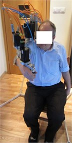
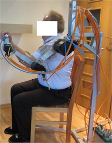
CAD model of ELISE robot that was generated using NX (Unigraphics) software. It is shown in Fig. 1. Additionally, a prototype of ELISE robot subjected to its first test is shown in Fig. 2.
The innovative solution of the robot frame has an ability to change the angle of robot arm. With this solution, it is possible to conduct exercises in transverse, sagittal and intermediate planes. These changes are possible with the help of a connecting element between the robot frame and the first part of robot arm. A first hole in this connecting element allows up to 90° of angular motion relative to the abscissa (the horizontal axis). Therefore, it is possible to change the plane of exercises from horizontal Fig. 3(a) to vertical Fig. 3(b). Additionally, this connecting element has a second hole, which allows the rotation of robot arm around the ordinate axis. With this innovative solution, it is possible to conduct rehabilitation in one of the eight intermediates planes (at intervals of 15°) (Fig. 4). It is possible to choose the angle of the robot arm between –45° to +90° from the horizontal plane. Changes to the plane of exercises are realized in a very fast and easy manner.
Fig. 1CAD model of ELISE robot for spastic upper limb rehabilitation
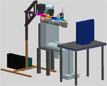
Fig. 2Prototype of ELISE robot for spastic upper limb rehabilitation
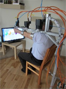
Fig. 3a) The robot arm is set in the horizontal plane and b) in the vertical plane
a)
b)
The robot arm consists of the three basic parts: arm module, forearm module and hand module. The kinematics structure of this solution corresponds to the upper limb. Additionally, this design incorporates supports to upper limb. The correct position of the upper limb during rehabilitation is ensured by the supports of arm and forearm. Consequently, additional support of the shoulder joint is not required. The length of the robot arm can be adjusted based on the anthropometric data of the patient. The length of the arm module can be changed in the range of 214 mm-280 mm. The length of the forearm module can be adjusted in the range of 208 mm-280 mm. The length of the hand module can be changed in the range of 75 mm-111 mm. The robot frame height is adjustable in the range of 600 mm-1200 mm.
The paretic upper limb is suspended under the robot arm. This solution allows to realize exercises for left or right limb and provide the maximum possible range of motion in exercises. Therefore, drive modules are placed on the robot arm. The area where the “ending” of the robot arm can be placed corresponds to the surface of motion utilized by 95 % of our population, taking into the account (at the same time) both tall patient (95 centyl men) and short patient (5 centyl women). Space required to install the ELISE robot has dimension of 1688 mm×1032 mm×815 mm.
The ELISE robot realizes rehabilitation exercises for left or right limb in the following ranges of motion:
• Shoulder joint: forward flexion 175° and backward extension 50° in sagittal plane; horizontal adduction (flexion) 30° and horizontal abduction (extension) 120° in horizontal plane; abduction 175° in front plane.
• Elbow joint: extension/flexion 120°.
• Wrist joint: dorsi-flexion (extension) 60° and palmar flexion (flexion) 60°.
In order to propose a design solution for this type of device as well as the selection of appropriate components for the patient (including the reduction gear and AC servomotor), it becomes necessary to conduct a detailed analysis of the kinematics and dynamics of the manipulator arm with the upper limb.
Fig. 4The robot arm is set in the intermediate planes
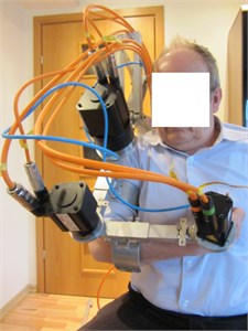
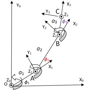
Fig. 5Kinematics diagram of the arm model
2. Kinematic theory
A spatial transformation between two consecutive links of a ELISE robot can be described by a set of parameters (, , , ) in Fig. 5. The first parameter is the joint angle . The second parameter is known as the link offset . The third parameter is the link length . The fourth parameter is the link twist . The definitions of these parameters are given as follows is the angle from the axis to the axis measured about axis, the distance between from the axis to the axis measured along axis, the angle from the axis to the axis measured along axis [28]. The model of ELISE robot is placed in transverse plane. This plane is very important in rehabilitation process.
Table 1D-H parameters of the manipulator
Frame | ||||
1 | 0 | 0 | ||
2 | 0 | 0 | ||
3 | 0 | 0 |
These four parameters are known as the Denavit–Hartenberg (D-H) parameters and will be specified for the 3 DOFs arm model in the following section (Table 1). Technical data is as following: – length of the arm module, – length of the forearm module, – length of the hand module, – shoulder joint angle, – elbow joint angle, – wrist joint angle. The frame is attached to shoulder joint. The frame is attached to elbow joint. The frame is attached to wrist. The frame is attached to rubber expander in hand. The length of robot arm was regulated for 95 centyli patient. Human body is symmetric, therefore this analysis was presented only for right upper limb.
2.1. Forward kinematics analysis
Forward kinematics refers to the geometrical representational of a coordinate frame located at any part of the manipulator with respect to a fixed coordinate frame usually attached to the base of the manipulator. The most common analysis is made over the tip of the manipulator, typically known as end-effectors, where the tool of the manipulator is located. The formulation derived from the forward kinematics is used to define the end – effectors position and orientation. The method is based on characterizing the relationship between links and joints with a (4×4) homogeneous transformation matrix. The matrix depends on four parameters associated with each link. Eq. (1-3) describe the kinematics of each link:
where the four quantities , , , are parameters associated with link and joint (Table 1). is the homogeneous transformation matrix.
By doing multiplication to the equations Eq. (1-3), the equation for the displacement of every module of ELISE robot arm is obtained Eq. (4):
where the homogeneous transformation matrix that expresses the position and orientation of with respect to is called, by convention, a transformation matrix, and is denoted by :
Matrix Eq. (5) contains displacement of an end-effector relative to the base frame and orientation of an end-effector relative to the base frame. Optional end coordinate can be represented by the matrix which is Eq. (6):
where defines a orientation of an end-effector relative to the base frame. The and define a displacement of an end-effector relative to the base frame.
2.2. Inverse kinematics analysis
In robotics, finding the joint angles of a robot to locate the end-effectors at a given position and orientation is known as inverse Eq. (7- 9):
Trajectory of rehabilitation exercise is then given by Eq. (10):
where the circle with centre coordinates (, ) and radius is the set of all points (, ).
Velocity of rubber expander Eq. (11):
where: – velocity of rubber expander, – the maximum velocity, – the rate of change, – the acceleration time, – the deceleration time.
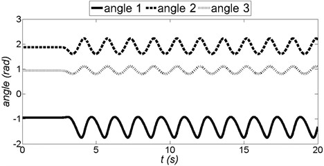
Kinematics properties of the manipulator hand are simulated using the robotic toolbox in Matlab simulation software (Fig. 6). Data for simulation are presented in Table 2.
Table 2Data for simulation
No | Description | Value / unit |
1 | length of the arm module | 0,28 m |
2 | length of the forearm module | 0,28 m |
3 | length of the hand module | 0,108 m |
4 | centre coordinate of trajectory | 0.3 m |
5 | centre coordinate of trajectory | 0 |
6 | radius of trajectory | 0.1 m |
7 | the maximum velocity | 0,4 m/s |
8 | the rate of change | 10 1/s |
9 | the acceleration time | 3 s |
10 | the deceleration time | 97 s |
11 | starting point coordinate | 0,3 m |
12 | starting point coordinate | 0,1 m |
13 | position vector | 0,1 m |
14 | orientation rubber expander | 1,7907 rad |
15 | starting position of the shoulder joint | –1 rad |
16 | starting position of the elbow joint | 1,9008 rad |
17 | – starting position of the wrist | 0,8899 rad |
3. Dynamics theory
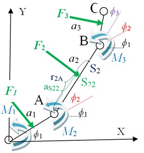
Dynamic property of a robot is mentioned as the changing rate of arm configuration depending on the torque at a joint produced by the actuator. Dynamics of a robot explains the equation for a movement, that is the way of the movement when a force is applied. There are two methods that can be used to find the movement equation; Newton-Euler and Lagrangian Formulation [29]. Dynamics diagram of the arm model is shown in Fig. 7.
Fig. 6Angle in each joints of the ELISE robot arm (angle 1 – shoulder joint, angle 2 – elbow joint, angle 3 – wrist)
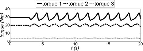
Technical data is as following: – torque motor 1 (shoulder joint), – torque motor 2 (elbow joint), – torque motor 3 (wrist), – spasticity force of the arm module, – spasticity force of the forearm module, – spasticity force of the hand module, – distance between elbow joint and spasticity force of the forearm module, – distance between elbow joint and centroid of the forearm module, – centroid of the forearm module, – point of application spasticity force of the forearm module.
Fig. 7Dynamics diagram of the arm model
3.1. Inverse dynamics analysis
Inverse dynamics is used to determine the torque to be applied on a robotic arm to produce the desired movement. Euler-Lagrange equations of motion are then given by Eq. (12):
and are the generalized coordinates and generalized forces due to applied forces corresponding to the generalized coordinates, respectively. The Lagrangian is difference between the kinetic and potential energy (Eq. 13) of the mechanical system under study, i.e.:
where denotes the Lagrangian, and and are respectively the total kinetic and potential energy of the system at hand. Note that the kinetic energy depends on both configuration, i.e. position and orientation, and the velocity of the links of a robotic system, whereas the potential energy depends only on the configuration of the links. Rehabilitation exercises are realized in transverse plane, therefore 0 and (Fig. 7). The dynamic equations of motion of 3-link 3-DOF robot are given possibility to define a torque motor Eqs. (14-16):
Table 3Data for simulation
No | Description | Value / unit |
1 | length of the arm module | 0,28 m |
2 | length of the forearm module | 0,28 m |
3 | length of the hand module | 0,108 m |
4 | mass of the arm module | 6,3 kg |
5 | mass of the forearm module | 3,28 kg |
6 | (mass of the hand module | 0,73 kg |
7 | moment of inertia arm module | 0,01570 kg·m2 |
8 | moment of inertia forearm module | 0,00706 kg·m2 |
9 | moment of inertia hand module | 0,00013 kg·m2 |
10 | spasticity force of the arm module | 210 N |
11 | spasticity force of the forearm module | 140 N |
12 | spasticity force of the hand module | 70 N |
13 | distance between shoulder joint and spasticity force of the arm module | 0,14 m |
14 | distance between elbow joint and spasticity force of the forearm module | 0,14 m |
15 | distance between wrist joint and spasticity force of the hand module | 0,054 m |
16 | distance between shoulder joint and centroid of the arm module | 0,256 m |
17 | distance between elbow joint and centroid of the forearm module | 0,251 m |
18 | distance between wrist joint and centroid of the hand module | 0,043 m |
Data for simulation are presented in Table 3. With the input of start and end coordinates, and also joint coordinates in the desired trajectory, the other property such as torque is determined (Fig. 8).
Fig. 8Torque in each joints of the ELISE robot arm (torque 1 – shoulder joint, torque 2 – elbow joint, torque 3 – wrist)
3.2. Forward dynamics analysis
Furthermore, the torque needed for a set of joint angle, velocity and acceleration can be found. It is important as it can be used to find the kinematics properties such as angle acceleration Eq. (17-19), angle velocity or joint angle:
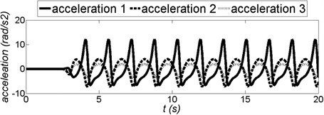
With the input of start and end coordinates, and also joint coordinates in the desired trajectory, the other property such as acceleration is determined (Fig. 9).
Fig. 9Acceleration in each joints of the ELISE robot arm (acceleration 1 – shoulder joint, acceleration 2 – elbow joint, acceleration 3 – wrist)
Upon consideration of requirements of the future device, including compact design, accuracy, safety and high reliability of future work, the components manufactured by SPINEA company were selected [31]. The actuators of the DriveSpin (DS) series combine optimised servomotors and TwinSpin gears resulting in a dynamic, high-performance and very compact servo actuator with high tilting torque capacity and integrated bearing. These actuators also included sensors. To drive each of the robot arms, the following components were used:
• For the arm module (with shoulder joint), it was used the DS-110-67-310014-01 (rated output torque 100 Nm and acceleration/braking torque 244 Nm).
• For the component of a forearm (with elbow joint), it was used the DS-70-75-310014-01 (rated output torque 50 Nm and acceleration/braking torque 100 Nm).
• For the component of a hand (with wrist joint), it was used the DS-50-63-310016-13 (rated output torque 18 Nm and acceleration/braking torque 36 Nm) [29].
For this technical data DS-110-67-310014-01 corresponds to the largest actuators of the DriveSpin line; 67 is the reduction ratio; number 3 means DC Bus voltage [320VDC (220VDC)]; and the last set of digits denotes sensors (temperature sensor PTC 11-K13 and resolver RE15-1-A14 (2 poles) and electrical connection. Very similar description is used for two other drive modules. Actuators of the DriveSpin are simultaneously basic elements of the construction. These actuators constitute the support element for another modules of the robot arm. Construction of servomotors and gear permits attachment of another component of the robot arm directly to the output shaft without a need for additional bearings. This type of solution with sensors and hardware/software ensure precise and safe rehabilitation.
The second functional unit of robot arm is the so-called “ending”, which is held by the patient in his hand. It consists of a “rubber expander” with a pneumatic system. These components were specifically created for the spastic hand rehabilitation. Gradual increase in pressure in “rubber expander” will increase its diameter. At the same time the patient’s spastic hand is slowly opening. For more details on the construction of “rubber expander” and its pneumatic system, the preliminary research will be presented in a separate article.
4. Hardware/software
The ELISE robot includes controls and software, which are friendly for patient and therapist. The control system takes into account the methods of rehabilitation, principles of the functioning of the human brain as well as the needs and expectations of patients and therapists.
From the viewpoint of control, ELISE robot can work in few basic modes:
• Diagnostics module – the program analyzes patient's current fundamental movement skills; the therapist obtains numerical and graphical information about patient's skills.
• Learning module – therapist moves patient's limb placed in the robot arm along the correct trajectory of rehabilitation exercise. The trajectory of exercises is remembered by the program.
• Exercise in passive mode – ELISE robot realizes the trajectory of rehabilitation exercise received from:
◦ Learning module.
◦ Special window in program’s interface where the therapist can define the trajectory and basic parameters of exercises.
• Exercise in active mode – the patient plays an educational game in virtual reality (VR) (or executes commands from therapist) and in the process moves his limb along the trajectory according to the pattern on the screen (e.g. maze game).
•Reports – numerical data collected during the subsequent stages of rehabilitation.
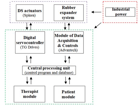
The system consists of five hardware/software modules (Fig. 10):
• Digital servocontroller (TG Drives) for DS actuators.
• Module of Data Acquisition & Controls (Advantech) for pneumatics.
• Central processing unit:
◦ Control program.
◦ Database.
• Therapist module.
• Patient module:
◦ VR (physical – education games in virtual reality).
The ELISE robot includes TG Drives digital servocontroller [32] with specialized software (TG motion) and Advantech module of data acquisition and controls. This software enables control of the DriveSpin system. A specialized software application for the control of this multi-module rehabilitation system had to be created. In addition, this software program controls DriveSpin actuators using database libraries supplied by TG Drivers. TG motion consists of software modules e.g.: virtual PLC module, connection module (PLC to servo-controllers, PLC to remote I/O). Virtual PLC controls all logical function of a machine and servo-controllers. and CNC module. PLC programming is realized in programming languages with supporting dll native library (e.g. C++). PLC module can control other devices in ELISE system via EtherCat. Virtual PLC accesses to memory space, where are shared registers of inputs and outputs and control registers of the servo amplifiers. It was necessary to write a PC panel program – a Win32 application, which allows control, diagnostics and service of the machine. Hardware of the TG motion which was installed in ELISE manipulator, is very easy modified according to the required counting power, numbers of the servo axis and I/O terminals. Therefore, it is the possibility of rapid expansion ELISE manipulator by a further degrees of freedom. CAN card – PC-I04/PCI is necessary for communication with servo-controllers and remote I/O modules. The card has two CAN outputs. Output CAN 1 is reserved for the servo-controllers and Output CAN 2 for remote I/O modules and other devices (frequency converters).
Fig. 10System block diagram
Basic information on the ELISE’s was presented in the description of the DriveSpin (DS) series actuators and rubber expander. In order to realize exercises and diagnostics in the shoulder joint, elbow joint and the wrist joint, DS actuators contain temperature sensor PTC 11-K13 and resolver RE15-1-A14 (2 poles). PTC-resistor temperature sensor gives a information a possible motor overload. A resolver is a rotary transformer that provides information on the rotor position angle. Main features of this resolver are operating temperature: –55 °C ... +155 °C and permissible speed: 20,000 rpm max. Another module with sensors is the innovative “rubber expander” with a pneumatic system. It was specifically created for the rehabilitation and diagnostic of the spastic hand. This system consists of the following sensors/elements e.g.:
• SMC series AS2002F-06, in-line type, compact speed controller for proper work of the rubber expander.
• 3/2 solenoid valve SMC series SYJ314M-5LOU-Q. Compact speed controller to ensure proper functioning of the rubber expander from the therapist’s software. Operating pressure range: 0.15 MPa-0.7 MPa.
• Compact proportional solenoid valve SMC series 2/2 PVQ31-5G-23-01. compact speed controller to ensure proper functioning in the diagnostic module. This valve is controlled by the therapist software.
Patient safety is very important therefore additional limit switches were introduced. Rehabilitation with ELISE manipulator is realized only in the ranges of motion available in the joints. This range is supervised in program, by limit switches and additional mechanical limitations in ELISE manipulator.
Therapist module contains all information about the rehabilitation process. This module was prepared for diagnostics of the patient, to define new rehabilitation exercises and to analyze the results (reports) [33, 34]. Patient module was prepared to conduct rehabilitation exercises in virtual reality [35-40], to supply the virtual assistant for the therapist and to easily extract information from reports. Detailed information about these modules are described in the second part of this chapter.
Therapist module, patient module and central processing unit can be launched either on a single computer or on three different computers. It is important to connect the digital servocontroller and the control module for pneumatics with the central processing unit. Therapist and patient can be in different locations. Robot modules were created to realize telerehabilitation [41].
Communication between modules was programming with TCP/IP sockets. To exchange information between the client and server, it was necessary to create a connection between them. XML schema is used for the exchange of data. Fig. 11 illustrates the idea behind the communication between various modules of the ELISE robot system.
Fig. 11The idea of the ELISE robot system and flow of information in this system
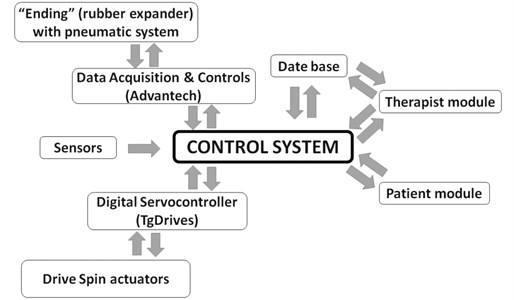
The control program is a master module of communication between system components. Communication is realized in real time. It was built as a stand-alone application in C # using Microsoft .NET Framework 4.0. The control program consists of four programming threads, which are responsible for communication between therapist module, patient module, actuators control system (TG Motion) and pneumatic control system. The control program connects everything together. It is responsible for communication between the layers of system software and layers of control system. Data transmitted between threads are synchronized.
The user interface was programmed using C# (Windows Forms) technology. It allows to view all information pertaining to the state of the ELISE robot. For proper operation, it requires the .NET 4.0 Framework and direct connection to the internet or intranet. It is necessary to establish communication with the control program. Prior to the start of rehabilitation procedure with the ELISE robot, the software program must be installed and opened on the personal computer. A user guide along with the information about the ELISE robot system is displayed on the first launch of the program. The main program window provides access to the database of patients. Therapist can choose an existing person from a list of patient or add a new person. When the potential patient meets with physiotherapist for the first time, it is necessary to collect basic patient data. When the physiotherapist chooses the patient name, he receives a list of possible methods of modern rehabilitation, including diagnosis, passive exercise, active exercise in virtual reality and reporting.
Diagnostics can be performed not only during the first rehabilitation session, but also at any time in the process of rehabilitation with the ELISE robot. Therapist obtains numerical information about health of the patient include the range of motion and strength. During the diagnosis, the patient is asked to perform movement with the maximum range of motion currently available at each joint of the upper limb. Moreover, it is possible to receive information from spastic of the muscles. The progress of rehabilitation is measured as the percentage of increment rather than the absolute value of the force. The sample report of diagnostics contains information about range of movement (in shoulder joint, elbow joint and wrist joint) and the change in the diameter of the “ending” recorded during hand rehabilitation.
The second step of rehabilitation process is the choice of rehabilitation exercises using one of the program options:
• Passive exercises:
◦ By learning module.
◦ By defining motion parameters.
• Active exercises:
◦ Therapist oral instructions.
◦ VR supported.
Window of the learning module (passive exercises) has a save button to record trajectory of exercises. With this button pressed, therapist moves the robot arm with patient's limb on the correct trajectory of rehabilitation exercise. Additionally, therapist can edit the parameters of exercise (such as speed, the number of repetitions and series or breaks between series). Moreover, passive exercises can be realized by defining motion parameters. Therapist defines range of movement in numbers (angles in shoulder joint, elbow joint and wrist joint) and the diameter of the “ending” during hand rehabilitation. Then therapist completes the remaining parameters of exercise, selection of the plane of movement, rehabilitated site, speed, number of repetitions, number of series, the time of any break between series and the angle by which the range of motion is increased in the next series of exercises.
Exercises in active mode were designed for patients who have to improve the precision of their movements or to undergo unloading exercises. If rehabilitation was solely based on motion, the success of convalescence would be insufficient. Therefore, this module was based on movement exercises, which incorporate biofeedback in virtual reality (VR). The patient must be fully engaged and focused on exercise. Very important part of rehabilitation is to introduce additional impulses for brain stimulation e.g. visual and auditory. With the aid of these stimulations, the ELISE robot is intended to speed up the process of recovery from damaged neuron connections in brain. This module contains a set of physical/education games in virtual reality. These games were prepared to improve the mechanisms of perceptual learning and motor learning. In particular, the patient should be able to associate sensory information with the operational data in his brain. While playing, the patient realizes common tasks from ordinary life. This innovative rehabilitation connects practical/social aspect of rehabilitation with movement exercises. VR was introduced for simulation of the real environment that is generated by dedicated computer software and can be experienced via a human – machine user-friendly interface in ELISE robot. The graphical user interface was built using WPF (Windows Presentation Foundation) technology, which is a module for creation of graphical user interfaces based on XML. It is part of the .NET 4.0 Framework. All of the games are based on WPF. Communication in ELISE robot was programmed using TCP/IP sockets. To exchange information between the client and server, it is necessary create a connection between them. XML schema is used for the interchange of data over this rehabilitation system. The server sends data about the current position of the manipulator to the client. The client sends the data on the progress in the game in virtual reality to the server. At the moment, the ELISE system runs properly on Windows operating system. However, there are no technical limitations to generate an equivalent version for internet explorer. Additionally, seniors shouldn’t be afraid to conduct rehabilitation exercises in VR. However, the patient’s mood and attitude are not always optimal. There are instances when he/she does not want to cooperate with the therapist. General fear acquired after the disease and reluctance to try something new are certainly undesired in the process of recovery after stroke and/or similar neural diseases. Therefore, another innovation of ELISE system is the introduction a virtual assistant of therapist. Nowhere in literature review does one find this type of tool as a virtual assistant of therapist. This innovative virtual assistant of therapist oversees the psychological aspect of rehabilitation. The virtual assistant introduces a nice atmosphere and encourages the patient to rehabilitation exercises. It provides the guide on basic operation of ELISE robot and principles of VR games. In case of inability of cooperation between the virtual assistant of therapist and the patient, virtual assistant will inform the therapist about this problem. Via the introduction of virtual assistant, the therapist gets more time to supervise the rehabilitation process or to introduce any corrections in exercises or work of several patients, simultaneously. Virtual assistant of therapist was designed in .NET Framework 4.0 and programmed using Visual Studio 2010 and Microsoft Expression Studio 3.0. System Requirements for ELISE robot are:
• Install .NET Framework 4.0.
• Windows XP with SP3 and Microsoft’s latest operating system.
• 800×800 screen resolution.
• Minimum requirements 512MB RAM.
• Minimum 100 MB free hard disk space.
Additional details about the scope of rehabilitation exercises in VR as well as the concept of virtual assistant of therapist will be presented in a separate article.
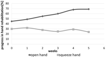
Reports are very important in the process of rehabilitation. They provide numerical information on the results and progress achieved in the subsequent stages of rehabilitation. All of this information is important for the therapist and patient. For the therapist, this information is an objective confirmation of the correct and effective selection of rehabilitation exercises or whether proposed exercises require adjustments. The patient receives measurements of angles in each joints and actual objective information about his progress in rehabilitation. Such data also serves as motivation for further work. We have to remember that patient’s subjective feelings are not always appropriate (correct). The following reports were generated using a log of exercises created during a rehabilitation program with ELISE robot. All of the reports were recorded in the database. The database report was based on server Mysql5/MSSQL 2008 Express. There is also an option to generate a detailed report and a summary report of rehabilitation exercises. These reports contain data of rehabilitation exercises in different periods of time. Their structures are the same. Typical report contains numerical data and their graphic illustrations. Summary report can be prepared after few days or weeks of rehabilitation process. Figs. 12-15 illustrate a summary report of the rehabilitation exercises of spastic upper limb after stroke. In this case, the problem of spastic upper limb appeared in elbow joint, wrist joint and squeeze hand. Moreover, it is possible to generate a summary report of force and moment of spastic upper limb.
Fig. 12Summary report of exercises in active mode in case of spastic upper limb (angles in shoulder joint)
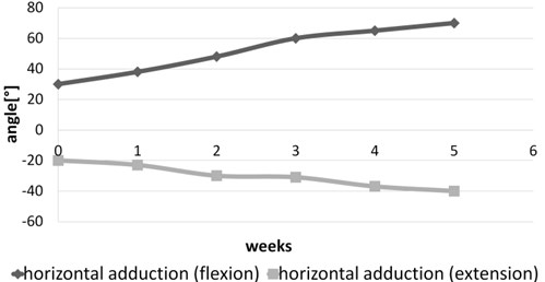
Fig. 13Summary report of exercises in active mode in case of spastic upper limb (angles in elbow joint)
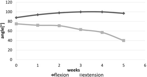
Fig. 14Summary report of exercises in active mode in case of spastic upper limb (angles in wrist joint)
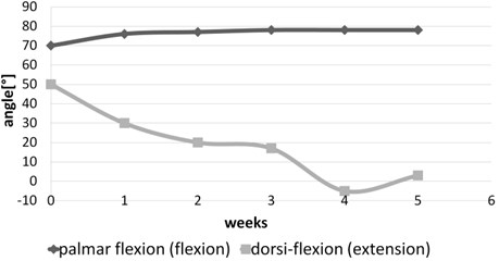
Fig. 15Summary report of exercises in active mode in case of spastic upper limb (progress in hand rehabilitation)
5. Conclusions
This paper presents the innovative design of the ELISE robot, which provides a complete rehabilitation system for the entire paretic upper limb of neurological patients. The ELISE robot is dedicated to individuals who suffered various types of injuries and illnesses, in particular to stroke survivors. This comprehensive rehabilitation process includes exercises of entire upper limb, taking into account a shoulder, forearm and hand. Using only one ELISE robot, therapist can conduct active and passive exercises of the right or left limb including hemiplegia or hemiparesis.
The design of ELISE robot is significantly simpler as compared to a similar group of rehabilitation devices used in the world. In addition, it has a similar or wider range of motion and a larger set of exercises relative to its competitors. Innovative and unconventional solution of the robot frame has an ability to offer rehabilitation exercises in different planes including transverse, sagittal and few intermediate (transverse) planes. The ELISE robot comprised of several modules. Robot was designed for flexible assembly and can be tailored to individual needs and unique expectations of each therapist and patient. This is possible thanks to the modular design of the robot arm and software. The ELISE robot will be sold in different configurations (e.g. without an expander or a set of virtual games or a virtual assistant of therapist). The concept of ELISE robot is universal. It enables future modifications and extensions to alternative actuators in order to realize rehabilitation exercises in space.
The ELISE system has been designed and implemented based on common experience in rehabilitation. It facilitates the robot-patient interaction compensating for some intrinsic limitations of traditional treatments. Perfect examples of these enhancements are diagnostic and report modules, a set of physical – education games in virtual reality based on activities of daily living and a virtual assistant of therapist.
Diagnostic module provides objective (numerical) data pertaining to patient's health condition at the beginning, during and at the end of the rehabilitation process. The therapist and patient can monitor the range of motion currently available at each joint of patient’s upper limb as well as strength of the upper limb itself. Furthermore, there exists a feature to generate numerical reports on progress as part of the reporting module. Although patient's feelings and suggestions are very important, they are not always entirely objective. On the contrary, a comprehensive report, which takes into consideration patient's feelings and suggestions in conjunction with numerical data of patient health and the knowledge and skills of the therapist, gives real opportunity to achieve success in rehabilitation. The report module was created based on the diagnostic program, so that therapist can check the numerical and graphical results of rehabilitation collected over multiple weeks or months. Moreover, it is possible to make adjustments and corrections to the previously established rehabilitation program.
A very important element, which supports and improves the rehabilitation process is biofeedback in virtual reality. It facilitates unlimited possibilities to simulate everyday activities. Practical – social character of all of games is another innovation of this project and makes the rehabilitation process more interesting and friendly for patients. All aspects of virtual reality rehabilitation can later be applied in daily life. This is also the first instance of application of the virtual assistant of therapist in rehabilitation. The virtual assistant of therapist establishes an element of psychological rehabilitation in the ELISE system.
Individualized approach to each patient was an essential aspect of the design of the ELISE robot. This idea appears practically at all stages of the project. A perfect example of such approach is demonstrated in a capability of easy adjustment of the length of robot arm to conform to the dimensions of patient’s limb.
In addition, strong emphasis was placed on the control and software, which were designed for user-friendliness to both the patient and therapist. Heavy and monotonous work of the therapist is simplified thanks to improved methods for defining and analysis of exercise. The comfort of conducted exercises, from the point of view of the physiotherapist and patient, was designed very thoughtfully and carefully.
In addition, the ELISE robot was designed for easier and faster set-up of rehabilitation process, for instance, a quick and effortless attachment of robot arm to patient's limb in the required plane of exercise. The comfort of therapist’s work was ensured by opportunities for rehabilitation of one – sided paralysis (left or right) using only one ELISE robot. This solution is more cost-effective as compared to other systems, which usually require two separate devices for the right and left paretic upper limb of stroke survivors. Particular attention was devoted to the safety of therapist and patient (e.g. design for safety and software security).
It should be emphasized, however, that the robot is not intended to replace the therapist. Instead, this robot is prepared to aid the therapist in long and exhausting process of rehabilitating the patient.
It should also be noted that the cost of energy and raw materials required to manufacture the robot is relatively low. Furthermore, used up robots can be easily disposed of.
References
-
Bovolenta F., Goldoni M., Clerici P., Agosti M., Franceschin M. Robot therapy for functional recovery of the upper limbs: a pilot study on patients after stroke. Journal of Rehabilitation Medicine, Vol. 41, Issue 12, 2009, p. 971-975.
-
Hayward K., Barker R., Brauer S. Interventions to promote upper limb recovery in stroke survivors with severe paresis: a systematic review. Disability and Rehabilitation, Vol. 32, Issue 24, 2010, p. 1973-1986.
-
Fazekas G., Horvath M., Troznai T., Toth A. Robot-mediated upper limb physiotherapy for patients with spastic hemiparesis: a preliminary study. Acta Dermato-Venereologica, Vol. 39, Issue 7, 2007, p. 580-582.
-
Posteraro F., Mazzoleni S., Aliboni S., Cesqui B., Battaglia A., Carrozza M. C., et al. Upper limb spasticity reduction following active training: a robot-mediated study in patients with chronic hemiparesis. Journal of Rehabilitation Medicine, Vol. 42, Issue 3, 2010, p. 279-281.
-
Sivan M., O’Connor R. J., Makower S., Levesley M., Bhakta B. Systematic review of outcome measures used in the evaluation of robot-assisted upper limb exercise in stroke. Journal of Rehabilitation Medicine, Vol. 43, Issue 3, 2011, p. 181-189.
-
Yozbatiran N., Berliner J., O’Malley M. K., Pehlivan A. U., Kadivar Z., Boake C., Francisco G. E. Robotic training and clinical assessment of upper extremity movements after spinal cord injury: a single case report. Journal of Rehabilitation Medicine, Vol. 44, Issue 2, 2012, p. 186-188.
-
Persson M., Fhager A., Dobsicek Trefna H., Yu Y., McKelvey T., Pegenius G., et al. Microwave-based stroke diagnosis making global prehospital thrombolytic treatment possible. IEEE Transactions on Biomedical Engineering, Vol. 61, Issue 11, 2014, p. 2806-2818.
-
Klamroth-Marganska V., Blanco J., Campen K., Curt A., Dietz V., Ettlin T., et al. Three-dimensional, task-specific robot therapy of the arm after stroke: a multicentre, parallel-group randomised trial. The Lancet Neurology, Vol. 13, Issue 2, 2014, p. 159-166.
-
Dobkin B. H. Strategies for stroke rehabilitation. The Lancet Neurology, Vol. 3, Issue 9, 2004, p. 528-536.
-
Francisco G. E., McGuire J. R. Poststroke spasticity management. Stroke, Vol. 43, Issue 11, 2012, p. 3132-3138.
-
Kalra L., Evans A., Perez I., Knapp M., Donaldson N., Swift C. G. Alternative strategies for stroke care: a prospective randomised controlled trial. The Lancet, Vol. 356, Issue 9233, 2000, p. 894-899.
-
Riener R., Nef T., Colombo G. Robot-aided neurorehabilitation of the upper extremities. Medical and Biological Engineering and Computing, Vol. 43, Issue 1, 2005, p. 2-10.
-
Pehlivan A. U., Sergi F., Erwin A., O’malley M. K., Yozbatiran N., Francisco G. E. Design and validation of the RiceWrist-S exoskeleton for robotic rehabilitation after incomplete spinal cord injury. Robotica, Vol. 32, Issue 8, 2014, p. 1415-1431.
-
Page S. Intensity versus task-specificity after stroke, how important is intensity? American Journal of Physical Medicine and Rehabilitation, Vol. 82, Issue 9, 2003, p. 730-732.
-
Foley N. C., Teasell R. W., Bhogal S. K., Doherty T., Speechley M. R. The efficacy of stroke rehabilitation: a qualitative review. Topics in Stroke Rehabilitation, Vol. 10, Issue 2, 2003, p. 1-18.
-
Pignolo L. Robotics in neuro-rehabilitation. Journal of Rehabilitation Medicine, Vol. 41, Issue 12, 2009, p. 955-960.
-
Sivan M., Gallagher J., Makower S., Keeling D., Bhakta B., O’Connor R. J., et al. Home-based Computer Assisted Arm Rehabilitation (hCAAR) robotic device for upper limb exercises after stroke: results of a feasibility study in home setting. Journal of NeuroEngineering and Rehabilitation, Vol. 11, Issue 1, 2014, p. 163-180.
-
Krebs H. I., Hogan N., Aisen M. L., Volpe B. T. Robot-aided neurorehabilitation. IEEE Transactions on Rehabilitation Engineering, Vol. 6, Issue 1, 1998, p. 75-87.
-
Venkatakrishnan A., Francisco G. E., Contreras-Vidal J. L. Applications of brain-machine interface systems in stroke recovery and rehabilitation. Current Physical Medicine and Rehabilitation Reports, Vol. 2, Issue 2, 2014, p. 93-105.
-
Jack D., Boian R., Merians A. S., Tremaine M., Burdea G. C., Adamovich S. V., Reece M., Poizner H. Virtual reality-enhanced stroke rehabilitation. IEEE Transactions on Neural Systems and Rehabilitation Engineering, Vol. 9, Issue 3, 2001, p. 308-318.
-
Carpinella I., Cattaneo D., Abuarqub S., Ferrarin M. Robot-based rehabilitation of the upper limbs in multiple sclerosis: feasibility and preliminary results. Journal of Rehabilitation Medicine, Vol. 41, Issue 12, 2009, p. 966-970.
-
Perry J. C., Rosen J., Burns, S. Upper-limb powered exoskeleton design. IEEE/ASME Transactions on Mechatronics, Vol. 12, Issue 4, 2007, p. 408-417.
-
Squeri V., Casadio M., Vergaro E., Giannoni P., Morasso P., Sanguineti V. Bilateral robot therapy based on haptics and reinforcement learning: feasibility study of a new concept for treatment of patients after stroke. Journal of Rehabilitation Medicine, Vol. 41, Issue 12, 2009, p. 961-965.
-
Bucca G., Bezzolato A., Bruni S., Molteni S. A mechatronic device for the rehabilitation of ankle motor function. Journal of Biomechanical Engineering, Vol. 131, Issue 12, 2009, p. 1-7.
-
Lo H. S., Xie S. Q. Exoskeleton robots for upper-limb rehabilitation: state of the art and future prospects. Medical Engineering and Physics, Vol. 34, Issue 3, 2012, p. 261-268.
-
Rosati G., Gallina P., Masiero S. Design, implementation and clinical tests of a wire-based robot for neurorehabilitation. IEEE Transactions on Neural Systems and Rehabilitation Engineering, Vol. 15, Issue 4, 2007, p. 560-569.
-
Freeman C. T., Hughes A. M., Burridge J. H., Chappell P. H., Lewin P. L., Rogers E. A model of the upper extremity using FES for stroke rehabilitation. Journal of Biomechanical Engineering, Vol. 131, Issue 3, 2009, p. 1-12.
-
Morales R., Badesa F. J., García-Aracil N., Sabater J. M. Pneumatic robotic systems for upper limb rehabilitation. Medical and Biological Engineering and Computing, Vol. 49, Issue 10, 2011, p. 1145-1156.
-
Zhu L., Gu Z., Shi J., Liu W. Research on dynamic performance and motion control of robot manipulator. Journal of Vibroengineering, Vol. 17, Issue 6, 2015, p. 3092-3103.
-
Masajedi P., Shirazi K. H., Ghanbarzadeh A. Verification of bee algorithm based path planning for a 6DOF manipulator using ADAMS. Journal of Vibroengineering, Vol. 15, Issue 2, 2013, p. 805-815.
-
Catalogue of Actuators. Spinea Company, 2015, http://www.spinea.sk/
-
Servoamplifiers – Digital Servoamplifiers TGA TGP, TGdrives Company, 2015, http://www.tgdrives.cz/en/
-
Gilliaux M., Lejeune T. M., Detrembleur C., Sapin J., Dehez B., Selves et al. C. Using the robotic device REAplan as a valid, reliable, and sensitive tool to quantify upper limb impairments in stroke patients. Journal of Rehabilitation Medicine, Vol. 46, Issue 2, 2014, p. 117-125.
-
Gilliaux M., Lejeune T., Detrembleur C., Sapin J., Dehez B., Stoquart G. A robotic device as a sensitive quantitative tool to assess upper limb impairments in stroke patients: a preliminary prospective cohort study. Journal of Rehabilitation Medicine, Vol. 44, Issue 3, 2012, p. 210-217.
-
Brunner I., Skouen J. S., Hofstad H., Strand L. I., Becker F., Sanders et al. A. M. Virtual reality training for upper extremity in subacute stroke (VIRTUES): study protocol for a randomized controlled multicenter trial. BMC Neurology, Vol. 14, Issue 1, 2014, p. 186-191.
-
Steinisch M., Tana M. G., Comani S. A post-stroke rehabilitation system integrating robotics, VR and high-resolution EEG imaging. IEEE Transactions on Neural Systems and Rehabilitation Engineering, Vol. 21, Issue 5, 2013, p. 849-859.
-
Lucca L. F. Virtual reality and motor rehabilitation of the upper limb after stroke: a generation of progress? Journal of Rehabilitation Medicine, Vol. 41, Issue 12, 2009, p. 1003-1006.
-
Burdea G., Popescu V., Hentz V., Colbert, K. Virtual reality-based orthopedic telerehabilitation. IEEE Transactions on Rehabilitation Engineering, Vol. 8, Issue 3, 2000, p. 430-432.
-
Feasel J., Whitton M. C., Kassler L., Brooks F. P., Lewek M. D. The integrated virtual environment rehabilitation treadmill system. IEEE Transactions on Neural Systems and Rehabilitation Engineering, Vol. 19, Issue 3, 2011, p. 290-297.
-
Fluet G. G., Deutsch J. E. Virtual reality for sensorimotor rehabilitation post-stroke: the promise and current state of the field. Current Physical Medicine and Rehabilitation Reports, Vol. 1, Issue 1, 2013, p. 9-20.
-
Cortese M., Cempini M., de Almeida Ribeiro P. R., Soekadar S. R., Carrozza M. C., Vitiello N. A mechatronic system for robot-mediated hand telerehabilitation. IEEE/ASME Transactions on Mechatronics, Vol. 99, 2014, p. 1-12.
Cited by
About this article

This work was supported in part by the Rzeszow University of Technology (PRz) under a Grant from the National Science Centre Poland (N518506039), The Office of the Marshal of the Podkarpackie Voivodeship in Rzeszow (8.2.2/I.6/6/10) and in part by the Vice-Rector for Research the Rzeszow University of Technology (U-778/DS/M).
