Abstract
Application of H∞ control for multimodal vibration suppression of a slewing spacecraft using piezoelectric actuators is presented in this paper. For treating vibration suppression independent of attitude control law while taking into account relative modal responses; a method for modeling effect of attitude maneuver excitations as modal disturbances is proposed. Commercial finite element software ANSYS is used for obtaining system model. Modifications of system model and selection of weights required for control synthesis are explained in detail. The method is applied for suppressing vibration of first two modes of a flexible spacecraft. Results showed effectiveness of the proposed method.
1. Introduction
Because of the high cost associated with transportation of materials to space, spacecraft are necessarily designed to be as light weight as possible. This low weight requirement together with the large size of current spacecraft make there structure extremely flexible. Most of the application of space structures involve stringent requirement on pointing accuracy and shape/configuration. These requirements have to be met in presence of vibrations induced from various excitation sources such as meteoroid impacts, thermal shocks and attitude maneuvers [1]. Due to high flexibility these space structures possess low frequency vibration modes which together with low damping can result in large settling times. Since for low frequencies passive damping techniques become ineffective, active vibration control is usually sought for such applications [2].
However, a major concern in application of active feedback control is phenomena of spillover – instability of closed-loop system caused by observation/excitation of un-modeled dynamics by sensors/actuators [3]. Since flexible structures are infinite order systems, the mathematical models used for designing controllers are essentially reduced order approximations of real plants. Hence, some dynamics is always left un-modeled and the selected control algorithm should have the capability to cope with these uncertainties. Moreover, due to paucity of available resources in space, the selection of actuators locations and design of control law should ensure optimal utilization of available resources.
A number of control techniques for active vibration control of flexible smart structures have been employed in the literature [4]. Although Positive Position Feedback (PPF) can avoid spillover under collocated actuator/sensor condition; design of controller for multimodal vibration reduction requires controlled modes to be well separated [5]. Optimal controller under given set of constraints can be obtained by using LQG (Linear Quadratic Gaussian). However, the controllers obtained are very sensitive to modeling errors and may compromise stability due to spillover [6]. On the other hand H∞ is an optimal control technique which can provide robustness to spillover by incorporating un-modeled dynamics as uncertainty at design level. Satisfaction of various constraints like actuator limits etc. and trade-off between performance and stability is also possible by using suitable weights. Moreover, controller design for MIMO systems and simultaneous suppression of multiple modes can be easily achieved through a unified and systematic procedure. Effective vibration control of piezoelectric smart structures using H∞ has been demonstrated in number of studies; however, the applications have been chiefly limited to constraint structures [7-13]. Moreover, vibration reduction is achieved for arbitrary excitation source without considering relative modal responses of controlled modes.
For spacecraft attitude operations that require small control actions, reaction/momentum wheels are used. However, during orbital correction maneuvers, such as north-south station keeping and slew, the required torque is normally too high for reaction/momentum wheels. Therefore, thrusters are normally used for attitude control during these maneuvers. The two major approaches for thruster control are bang-bang control and pulse modulation [14]. Also VSC (variable structure control) represents a systematic approach to the design of on/off control laws for multivariable systems, which is good matching to the thruster actuator mode commonly used in a satellites [15]. Hence suppressing vibrations independent of attitude (slewing) motion control law/method can give significant advantages.
For treating vibration suppression independent of attitude control law while taking into account relative modal responses; a method for modeling effect of attitude maneuver excitations as modal disturbances is proposed in this paper. The method is applied for suppressing first two modes of a slewing spacecraft controlled by constant amplitude thrusters. The chosen spacecraft model consists of rigid hub and a flexible panel. The location of spacecraft’s rotational axis is chosen such that the controlled modes are closely spaced. Moreover, damping of the modes is chosen as 0.5% so that some of the characteristics of modern spacecraft can be imitated.
The rest of the paper is as follows: mathematical modeling is described in Section 2; modification of system state space matrices and selection of weights required for control synthesis are discussed in Section 3; simulation results are presented in Section 4 and finally Section 5 concludes this paper.
2. Modeling
The equations governing dynamic response of a structure with piezoelectric actuators can be expressed using Finite element formulation as [13]:
where [], [], [], [] and [] are the, mass, damping, elastic stiffness, piezoelectric coupling and dielectric stiffness matrices, respectively; denotes vector of structural displacement degrees of freedom (D.O.F); is the applied mechanical load vector; is the vector of applied piezoelectric actuator voltages; [] is a matrix for locations of applied mechanical loads and [] is a matrix of actuator locations with corresponding capacitances.
However, the order of structural D.O.F in Eq. (1) is usually very large, which makes its use for control design purposes infeasible. Therefore, modal transformation is usually applied for obtaining mathematical model of manageable size. This transformation is represented as:
where [] is a square matrix with columns corresponding to eigenvectors of un-damped homogenous system of Eq. (1) and represents modal coordinates. Using Eq. (2), Eq. (1) can be transformed in modal coordinates, which with assumption of proportional damping can be expressed in abbreviated form as:
For the choice of state vector , and eigenvectors of Eq. (2) normalized with respect to mass matrix of Eq. (1), Eq. (3) can be expressed in sate space form as:
where the system matrices have the following structure:
where and are modal damping ratio and natural frequencies, respectively and subscript , , denote number of modes used in transformation, number of applied mechanical loads and number of piezoelectric actuators, respectively.
Measured system outputs can also be represented in state space form as follows:
where subscript denotes the number of measured outputs; is a matrix of dimension , which transforms modal coordinates into physical outputs; matrix with dimension is feed through matrix for applied mechanical loads and matrix with dimension is feed through matrix for applied actuator voltages.
To include the effect of modal disturbances, Eq. (4) can be modified as follows [16]:
where represents a vector of modal forces and has the following structure:
The modal response of system can be obtained as:
with .
For a given system, coefficient matrices of Eqs. (4-5) can be obtained through commercial finite element software; which upon suitable modification (discussed in Section 3 of this paper) can be used in system models used for controller design. Use of ANSYS for closed loop simulations of piezoelectric smart structures has been done in [17, 18]. Experimental Verification of closed loop simulations performed in ANSYS has been demonstrated in [19]. In this paper coefficient matrices of Eqs. (4-5) for the spacecraft model are obtained by using ANSY.
The model of the spacecraft (Fig. 1) used in this paper consist of a flexible panel attached to a rigid hub. To provide control action Twenty-four piezoelectric actuators (twelve on each side of panel) are used; a collocated strain gauge is used to provide feedback measurements. For maximizing controllability piezoelectric actuators are placed in region of high modal strain energy density of controlled modes [20-22]. Relevant sizes and locations of each component are also shown in Fig. 1(a).
To develop the corresponding finite element model in ANSYS, the rigid hub is modeled as a concentrated mass and constraint equations are used to connect it with flexible panel. SOLID 186, SOLID 226 and MASS 21 elements are used to model flexible panel, piezoelectric actuators and rigid hub, respectively. Material properties for modeling flexible panel are taken as; (Modulus of elasticity) = 69×109 N/m2; (Density) = 2710 kg/m3; (Poisson’s ratio) = 0.32. Twenty-four Dura Act patches (P-876.A15) of ©Physik Instrumente (PI) are used as piezoelectric actuators [23]. The properties of piezoelectric actuators are given in Table 1. Moment of inertia of rigid hub about rotation axis is taken as 11 kg/m2. A global element size of 15 mm is used for meshing; the developed finite element model is shown in Fig. 1(b).
Fig. 1Model of spacecraft
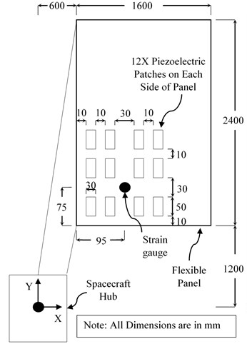
a) Sizes and locations of components
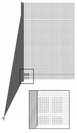
b) Corresponding FEM model
Table 1Material properties of piezoelectric actuators
Compliance at constant electric field [m2/N] | Piezoelectric strain matrix [m/V] | Relative permittivity at constant stress | Density [kg/m3] | Free space permittivity [F/m] | |||
S11 | 1.590×10⁻¹¹ | d31 | –1.74×10⁻¹⁰ | ε11 | 1649 | 7800 | 8.85×10⁻¹² |
S33 | 2.097×10⁻¹¹ | d33 | 3.94×10⁻¹⁰ | ε22 | 1649 | ||
S12 | –5.699×10⁻¹² | d15 | 5.35×10⁻¹⁰ | ε33 | 1750 | ||
S13 | –7.376×10⁻¹² | ||||||
S44 | 4.492×10⁻¹¹ | ||||||
S66 | 4.319×10⁻¹¹ | ||||||
For obtaining Coefficient matrices of Eqs. (4-5), modal analysis is performed by constraining all DOF except rotation about -axis at concentrated mass (rigid hub). Torque about -axis and voltage input to piezoelectric patches are taken as load vectors. The output vector consists of: (a) tip displacements in -direction at lowest, highest and mid-point of the right most edge of panel; (b) strain output for feedback. Uniform modal damping ratio of 0.5 % is assumed and system model is developed by considering first ten modes (where first mode corresponds to rigid body mode). Details for performing modal analysis and extraction of coefficient matrices can be found in ANSYS user manual [24]. The obtained system matrices are given in appendix A2; where in the order given, columns of matrix B correspond to applied torque from attitude control thrusters and actuation voltage of piezoelectric actuators, respectively; while the rows of matrix C correspond to tip displacements at lower, mid and highest point of panel and strain gauge feedback, respectively.
3. Controller design
Consider the system block diagram shown in Fig. 2(a). The control objective is to keep performance output reasonably small for specified disturbance levels and control signal limitations. In H∞ framework, this performance objective is achieved by minimizing the H∞ norm of closed-loop transfer matrix from external disturbances to regulated variables (performance output and control signal) over the set of stabilizing controllers. However, because many different objectives are to be represented by a single H∞ norm objective on a closed-loop transfer function, weighing of input and output signals is necessary. The general disturbance rejection problem of Fig. 2(a) with additional weights necessary for representing closed loop performance objectives in H∞ framework is shown in Fig. 2(b). Where, the weights are used to account for relative magnitude of external disturbances, frequency dependence of signals and relative importance of the magnitudes of regulated variables in a manner that when ∥ (weighted closed-loop transfer function from exogenous influences to regulated outputs)∥∞ < 1, the desired objectives are fulfilled [25].
Fig. 2Block diagram for disturbance rejection problem

a) Un-weighted

b) Weighted
For suppressing vibrations independent of attitude control law/method while ensuring robustness to spillover, the following procedure is adopted in this paper: (a) Modification of system model, (b) Uncertainty modeling of unmolded higher modes, (c) weight selection, and (d) system interconnection, controller synthesis and controller order reduction.
3.1. Modification of system model
For the constant amplitude attitude control thrusters considered in this paper, maneuver commands are composed of rectangular pulses. The maximum modal response of a mode to a rectangular pulse depends on the width and amplitude of the pulse [26]. For the spacecraft considered in this paper maximum possible contribution of flexible modes to the vibratory motion of panel tip are given in Table 2. Since, the overall response is largely dominated by the first two flexible mode, a two mode model is considered for control design. However, neglecting higher modes can cause significant errors in locations of in-bandwidth zeros and DC gain of the system. These errors if not accounted properly can result in significant degradation of controller performance with actual systems [27]. In this paper correction for the errors introduced by out-of-bandwidth modes is made by adding DC gain of neglected modes as feed-through term in the reduced model [28].
Bode magnitude plots of transfer function from piezoelectric-actuator voltage to measured strain for full, reduced and corrected reduced models are shown in Fig. 3; where the reduced model is obtained by deleting the rows and columns corresponding to higher modes of system matrices given in appendix A and corrected reduced model is obtained by putting DC gain of neglected modes in the feed-through matrix of actuator input in the reduced model.
Table 2Contribution of modes to vibration amplitude of flexible panel tip
Mode | Amplitude [m] | Mode | Amplitude [m] |
1 (Rigid mode) | – | 6 | 0.2281e-003 |
2 | 8.2896e-003 | 7 | 0.0994e-003 |
3 | 3.9495e-003 | 8 | 0.0072e-003 |
4 | 0.1275e-003 | 9 | 0.0105e-003 |
5 | 0.1169e-003 | 10 | 0.0073e-003 |
Fig. 3Frequency response from actuator voltage to strain output
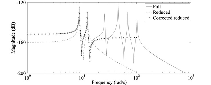
Controller design in H∞ frame work requires that: all system modes must be stabilizable from the control inputs and detectable from the measurement output. Since the rigid mode of the spacecraft is uncontrollable/unobservable from piezoelectric-actuators/ sensor gauge, this mode is removed from the system model for control design. For treating vibration suppression independent of attitude control method/law, effect of attitude maneuver excitations is incorporated as modal disturbances. The procedure for determining scale factor (weights) of modal disturbances required for H∞ control synthesis is explained in Section 3.3. Moreover, system input corresponding to applied torque is also removed because its effect is modeled as modal disturbances.
The final system model after: model reduction, correction for out-of-bandwidth modes, addition of modal disturbance input, addition of modal response output and removal of rigid mode and applied torque is given by:
3.2. Uncertainty modeling of unmolded higher modes
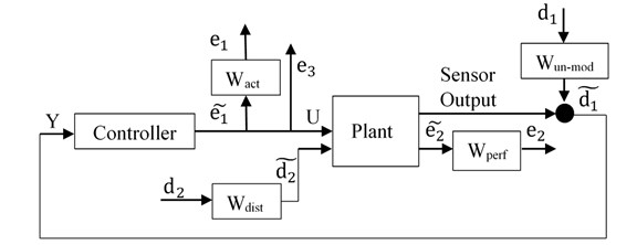
A major problem associated with controllers designed using reduced order system model is the phenomena of spillover. In H∞ framework robustness to spillover can be provided by bounding the norm of an additional disturbance to output transfer function. Consider block diagram shown in Fig. 4(a), where the effects of un-modeled modes are included as additive uncertainty. By small gain theorem [29-30] system stability in presence of un-modeled dynamics is guaranteed, if for for or . For including these bounds in the overall objective of H∞ synthesis i.e. the system can be modeled as shown in Fig. 4(b); where the connections to unmolded dynamics have been removed and the corresponding effects are incorporated by scaling input d1 with weighing function (Usually taken as an upper bound to un-modeled dynamics).
Fig. 4Un-certain system representation
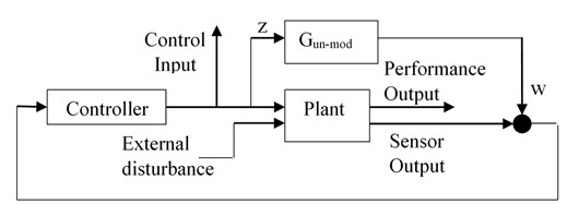
a) With additive un-certainty
b) Equivalent representation in H∞ framework
3.3. Weights selection
The interconnection of plant and associated weights used to design the controller is shown in Fig. 4(b). Where d2 corresponds to vector of modal disturbance and performance output is taken as vector of modal responses. As a general rule the weights used for scaling inputs (, ) can be chosen to represent the respective magnitude of exogenous influences as a function of frequency and the weights used for scaling outputs (, ) are chosen as inverse of the bound on desired respective output [25]. However, sometime additional scaling becomes necessary because a single signal has to be used for representing multiple objectives. The guidelines used for selecting weights and their selected values are as follows.
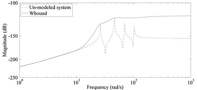
Since the condition for stability in presence of un-modeled dynamics provided through small gain theorem i.e. is based on infinite norm of un-modeled dynamics, a transfer function which bounds the response of un-modeled dynamics can be used as weighting function for including the effects of un-modeled dynamics. However, the weight must be judiciously selected as a conservative bound for residual dynamics will result in compromise of achievable performances for given system parameters. Moreover, system output (Fig. 4(b)) used for establishing stability condition is actually un-weighted control signal , therefore it will be removed from final interconnection due to redundancy. For representing stability condition through the bounding function has to be scaled by therefore the weighting function used for un-modeled dynamics is taken as:
In this paper fifth order weight shown in Fig. 5 is used for representing bound on un-modeled dynamics.
Fig. 5Approximation of residual dynamics by fifth order bound
H∞ control synthesis is fundamentally a frequency domain design technique. In steady state the H∞ control objective can be interpreted as minimizing the maximum value of ratio between response (regulated variables) and disturbances (considered as sinusoidal inputs) of a transfer matrix for all frequencies. Because multiple objectives are to be met by a single cost function, frequency-dependent weighting functions are used to account for: relative magnitude of disturbances, frequency dependence of signals and relative importance of the magnitudes of regulated variables.
Since, for the case considered in this paper disturbance is not sinusoidal; its effect is incorporated as modal disturbances. Where the weight for each modal disturbance is calculated by dividing maximum possible modal amplitude due to maneuver commands of the respective mode by its modal amplitude due to unit sinusoidal modal force. Scaling modal disturbance in this manner lead to same modal response ratios during control synthesis as produced by the maneuver commands. Also, the response of a flexible structure to an impulse is composed of modal responses at respective natural frequencies; another advantage of using modal disturbances is that frequency dependence of disturbance weights is not necessary, because the response to a modal disturbance is only dominant near the natural frequency of the respective mode.
For the two mode reduced model is taken as 2×2 diagonal matrix, where the diagonal entries are calculated by the procedure described above. Finally, by maintaining the ratios of diagonal entries, is scaled iteratively along with and for finding a suitable controller. The final value of is taken as:
For reducing settling time of induced vibrations the damping of modes having dominant contribution to the panel response has to be increased. For the sinusoidal modal disturbance considered in the control synthesis the respective modal responses are inversely proportional to their corresponding damping. Hence, modal responses are taken as measure of performance and is used to penalize responses according the desired level of damping.
In this paper is taken as 2×2 diagonal matrix; where each diagonal entry is taken equal to the inverse of the desired closed-loop modal response. Since, the relative amplitude of modal responses have been accounted in disturbance modeling; desired level of closed-loop modal responses can be selected as percentage of the corresponding open-loop responses to scaled disturbances. This results in modal damping ratios proportional to the respective weights used in penalizing modal responses. The value of is taken as:
where each diagonal entry respectively corresponds to inverse of 30 % of the open-loop responses of 1st and 2nd mode to scaled disturbances.
can be used for two purposes: to limit actuator outputs below certain maximum limit and to roll-off controller response at higher frequencies for preventing spillover. In this paper prevention to spillover is provided through un-certainty modeling, hence, is used to limit the maximum actuator output only. For the selected actuators maximum input voltage is 240 volts. To keep the input voltage within limits is adjusted iteratively along with and for achieving this objective. The final value of is taken as 0.01.
3.4. System interconnection, controller synthesis and reduction
The transfer matrix of the interconnected system (Fig. 4(b)) required for control synthesis can be obtained by following the procedure described in [29, 30] or more easily by using the SYSIC command of MATLAB’s robust control toolbox. In this paper SYSIC command is used to connect the plant model with relevant weights described in previous section. The orders of inputs and outputs to the system are taken as:
The controllers is obtained by applying standard 2-Riccati solution to the interconnected transfer matrix; HINFSYN command of MATLAB’s robust control toolbox is used for this purpose.
Finally using “Balanced model truncation via square root method” [25, 31], 5th order reduced controller is obtained.
4. Results
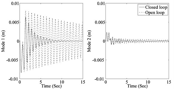
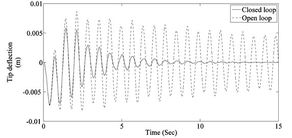
To evaluated the performance of designed controller, system response to two actuator pulses giving maximum modal response of 1st and 2nd mode respectively is determined. The 1st pulse has an amplitude of 10 Nm and a width of 1.06 Sec (1.5 times the time period of 1st flexible mode), while the second pulse has an amplitude of 10 Nm and a width of 0.755 Sec (1.5 times the time period of 2nd flexible mode). Resulting contributions of modes to panel tip vibration, panel tip vibration and controller response for the 1st pulse are shown in Fig. 6. While contributions of modes to panel tip vibration, panel tip vibration and controller response for the 2nd pulse are shown in Fig. 7. It can be seen that the controller is able to damp out both modes effectively while keeping the controller output within actuator limits.
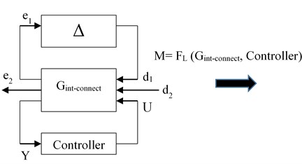
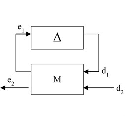
In H∞ framework stability margin of the system under presence of un-modeled dynamics is calculated by using structured singular value analysis. The transformation of system model required for performing structured singular value analysis is shown in Fig. 8. Where is obtained by replacing in interconnected model of Eq. (10) with actual residual dynamics and the un-certain transfer matrix is added as a feedback around transfer matrix form d1 to e1. Stability margin of the system is calculated as follows [32]:
1) Connect with the designed controller and uncertain matrix to obtain un-certain closed-loop system as shown in Fig. 8(a).
2) Perform LFT (lower fractional transformation) of with the designed controller to obtain matrix M.
3) Obtain the frequency response of i.e. frequency response of the part of matrix that is connected to the uncertain matrix .
Fig. 6System response to 1st pulse
a) Contributions of modes to panel tip vibration
b) Panel tip vibration
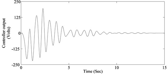
c) Controller response
4) Since in the system model (Fig. 4) un-modeled dynamics are represented as additive uncertainty, assume a full 1×1 complex block structure for .
5) Compute structured singular value bounds for the frequency response obtained in step 3; MUSSV command of MATLAB’s robust control toolbox can be used for this purpose.
The upper bound of structured singular value obtained by performing steps 1 to 5 is shown in Fig. 9. The robust stability margin is the reciprocal of the structured singular value. The peak value of 0.259 of the structured singular value indicates that the closed loop will remain stable for up to 386.1 % (reciprocal of 0.259) of the specified uncertainty. Which shows the designed controller is robust to spillover.
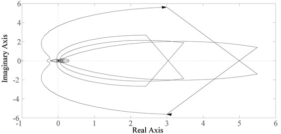
Stability of the system can also be determined using Nyquist criterion. The Nyquist plot of the system is shown in Fig. 10. It is evident that the contour does not encircle the (–1, 0) point and the system is stable. The minimum gain and phase margin of the system are obtained as 10.2 dB and 67.7 deg respectively.
Fig. 7System response to 2nd pulse
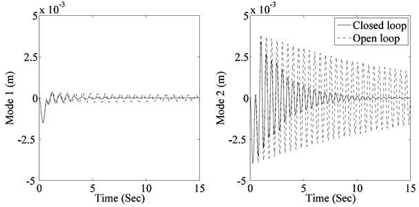
a) Contributions of modes to panel tip vibration
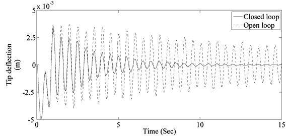
b) Panel tip vibration
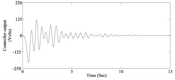
c) Controller response
Fig. 8Transformation of system matrix for structured singular value analysis
a)
b)
Fig. 9Upper bounds of structured singular value
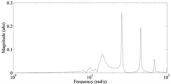
Fig. 10Nyquist diagram
5. Conclusions
Application of H∞ control for active vibration suppression of a slewing spacecraft by using piezoelectric actuators is presented. By treating attitude maneuver excitations as modal disturbances, problem of vibration suppression is made independent of control law/method. System model required for control synthesis is obtained by modifying mathematical model obtained from ANSYS. As complex smart structures can be easily modeled using ANSYS, the method can be applied for obtaining suitable models of complex real life structures. Moreover, selection of weights for controller design and relative scaling of system input-output signals necessary for formulating meaningful control objectives is also explained in detail.
To assess the viability of proposed method, the method is applied for vibration suppression of a flexible spacecraft controlled constant amplitude attitude control thrusters. Simulations results showed that the method can effectively suppress vibration of multiple modes without causing spillover. Proof of system stability in presence of un-modeled dynamics is also given by structured singular value analysis.
References
-
Lewis Jackson A., Inman Daniel J. Finite element modeling and active control of an inflated torus using piezoelectric devices. Journal of Intelligent Material Systems and Structures, Vol. 12, 2001, p. 819-833.
-
Fanson James L. An Experimental Investigation of Vibration Suppression in Large Space Structures Using Positive Position Feedback. Ph.D. Thesis, California Institute of Technology, Pasadena, California, 1987.
-
Hyland D. C., Junkins J. L., Longman R. W. Active control technology for large space structures. Journal of Guidance, Control, and Dynamics, Vol. 16, Issue 5, 1993, p. 801-821.
-
Gupta Vivek, Sharma Manu, Thakur Nagesh Mathematical modeling of actively controlled piezo-smart structures: a review. Smart Structures and Systems, Vol. 8, Issue 3, 2011, p. 275-302.
-
JFanson L., Caughey T. K. Positive position feedback control for large space structures. AIAA Journal, Vol. 28, Issue 4, 1990, p. 717-724.
-
Vasques C. M. A., Rodrigues J. Dias Active vibration control of smart piezoelectric beams: Comparison of classical and optimal feedback control strategies. Computers and Structures, Vol. 84, 2006, p. 1402-1414.
-
Qiu Zhicheng, Ling Defang Finite element modeling and robust vibration control of two-hinged plate using bonded piezoelectric sensors and actuators. Acta Mechanica Solida Sinica, Vol. 27, Issue 2, 2014, p. 146-161.
-
Jiang Jian-Ping, Li Dong-Xu Robust H∞ vibration control for smart solar array structure. Journal of Vibration and Control, Vol. 17, Issue 4, 2010, p. 505-515.
-
Iorga Lucian, Baruh Haim, Ursu Ioan H∞ control with µ-analysis of a piezoelectric actuated plate. Journal of Vibration and Control, Vol. 15, Issue 8, 2009, p. 1143-1171.
-
Iorga Lucian, Baruh Haim, Ursu Ioan A review of H∞ robust control of piezoelectric smart structures. Applied Mechanics Reviews, Vol. 61, Issue 4, 2008.
-
Rao K., Natesan Kannan, Bhat M. Seetharama, Ganguli Ranjan Experimental demonstration of H∞ control based active vibration suppression in composite fin-tip of aircraft using optimally placed piezoelectric patch actuators. Journal of Intelligent Material Systems and Structures, Vol. 19, 2008, p. 651-669.
-
Xie S. L., Zhang X. N., Zhang J. H., Yu L. H∞ robust vibration control of a thin plate covered with a controllable constraint damping layer. Journal of Vibration and Control, Vol. 10, 2004, p. 115-133.
-
Chang W., Gopinathan Senthil V., Varadan V. V., Varadan V. K. Design of robust vibration controller for a smart panel using finite element model. Journal of Vibration and Acoustics, Vol. 124, 2002, p. 265-278.
-
Song Gangbing, Agrawal Brij N. Vibration suppression of flexible spacecraft during attitude control. Acta Astronautica, Vol. 49, Issue 2, 2001, p. 73-83.
-
Hu Qinglei, Ma Guangfu Variable structure control and active vibration suppression of flexible spacecraft during attitude maneuver. Aerospace Science and Technology, Vol. 9, 2005, p. 307-317.
-
Callahan J., Baruh H. Active control of flexible structures by use of segmented piezoelectric elements. Journal of Guidance, Control, and Dynamics, Vol. 19, 1996, p. 808-815.
-
Meng Guang, Ye Lin, Dong, Xing-jian, Wei Ke-xiang Closed loop finite element modeling of piezoelectric smart structures. Shock and Vibration, Vol. 13, 2006, p. 1-12.
-
Dong Xingjian, Peng Zhike, Zhang Wenming, Hua HongXing, Meng Guang Research on spillover effects for vibration control of piezoelectric smart structures by ANSYS. Mathematical Problems in Engineering, Vol. 2014, 2014, p. 1-8.
-
Malgaca L., Karagulle H. Numerical and experimental study on integration of control actions into the finite element solutions in smart structures. Shock and Vibration, Vol. 16, 2009, p. 401-415.
-
Ferrari Giovanni, Amabili Marco Active vibration control of a sandwich plate by non-collocated positive position feedback. Journal of Sound and Vibration, Vol. 342, 2015, p. 44-56.
-
Aldraihem Osama J., Singh Tarunraj, Wetherhold Robert C. Optimal size and location of piezoelectric actuator/sensors: practical considerations. Journal of Guidance, Control, and Dynamics, Vol. 23, Issue 3, 2000, p. 509-515.
-
Joshi, Khot S. M. Smart actuator effectiveness improvement through modal analysis. Journal of Vibration Engineering and Technologies, Vol. 6, 2007, p. 195-208.
-
PI Datasheet P-876, Physik Instrumente (PI). GmbH and Co. KG, http://www.piceramic.com/.
-
ANSYS 14.5 Help. ANSYS, Inc., Canonsburg, PA, USA.
-
Matlab2014a Help. The MathWorks, Inc., 2014.
-
Ray Clough W., Joseph Penzien Dynamics of Structures. Computers and Structures, Inc., USA, 1995.
-
Moheimani S. O. R., Heath W. P. Model correction for a class of spatio-temporal systems. Automatica, Vol. 38, 2002, p. 147-155.
-
Bisplinghoff R. L., Ashley H. Principles of Aeroelasticity. Dover, New York, 1975.
-
Zhou K., Doyle J. C., Glover K. Robust and Optimal Control. Prentice-Hall, Englewood Cliffs, NJ, 1996.
-
Zhou K., Doyle J. C. Essentials of Robust Control. Prentice-Hall, Englewood Cliffs, NJ, 1998.
-
Safonov M. G., Chiang R. Y. A Schur method for balanced model reduction. IEEE Transaction on Automatic Control, Vol. 34, Issue 7, 1989, p. 729-733.
-
Balas G. J., Doyle J. C., Packard A. μ-Analysis and Synthesis Toolbox for use with MATLAB. The MathWorks, Natick, MA, 2001.
