Abstract
Piezoelectric resonators are widely applied in frequency control components in electronic devices, digital computers, and telecommunication. The stability of these resonators are affected by force-frequency and temperature-frequency effects. In this paper, a simple laboratory measurement method is introduced for measuring the force-frequency effect in piezoelectric resonators. The method employs the parallel resonance frequency of the resonator. It has been shown that the frequency shift of the parallel resonance frequency is very close to that of series resonance, and can be used instead for similar applications. Accordingly, the frequency shift of an AT-Cut quartz resonator which is subjected to a pair of opposed forces is measured. Also, the frequency shift is calculated by the finite element method. The numerical model and experimental results are in a good accordance. The obtained results can be used for better understanding of the force-frequency effect, its practical measurement to be used in simulation of crystal resonators and sensors behavior. Its industrial application will include design of down-hole sensors with better accuracy and robustness.
1. Introduction
Because crystal devices such as quartz crystal resonators and oscillators have high stability against an environment change such as temperature, they are used as frequency control devices in electronic devices, digital computers, and telecommunication. Modern requirement for frequency stability in telecommunications ranges from 0.1 to 50 ppb/day [1]. Therefore, the crystal resonators should be designed in such a way that this high frequency stability is achieved. The stability of the crystal resonators is mainly affected by some non-linear effects like force-frequency, and temperature-frequency effect. Another industrial application of quartz crystal resonators is in sensor technology. Currently, many sensors work on the principle of force-frequency effect. It is the aim of this paper to investigate the force-frequency effect both experimentally and numerically.
A piezoelectric resonator usually consists of a piezoelectric disk equipped with two metal electrode. Application of the alternating electric field to the piezoelectric resonators brings about mechanical vibrations in the resonator [2]. When the frequency of the electric field equals the natural frequency of the crystal, the resonance occurs. To obtain high frequencies, usually the thickness shear vibration mode is used. If the resonator is subjected to external perturbations like thermal and mechanical loads, due to some non-linear effects like force-frequency effect, its thickness shear mode resonance frequency is changed, and the stability of the output frequency is reduced [3]. The change in the resonance frequency of the crystal due to application of a pair of diametrically opposite forces is named force-frequency effect [4].
The force-frequency effect in vibrating crystals were first noticed by Bottom for AT-cut and BT-cut quartz crystals [5]. Gerber [6] and Mingins [7] showed that the magnitude of the force-frequency effect is dependent on direction of the applied loads relative to the crystallographic directions of the crystal. Ratajski [8] quantified the force-frequency effect and introduced the force-frequency constant for the circular resonators. He measured the force-frequency constants for singly rotated cuts of quartz. Dauwalter described the effect of the temperature change on the force-frequency coefficient [9]. He demonstrated the temperature dependence of the force-frequency coefficient is a function of the azimuth angle between the crystallographic axis and the direction of the applied force. For measuring the frequency shifts at higher temperatures, he employed an oscillator circuit for generating the variable electric signal. The frequency change was measured by a frequency counter. The temperature dependence of rotated -cuts of quartz was investigated by Ernisse [10]. In this work, for measuring the frequency shift, the crystal is incorporated into an oscillator circuit located outside of a furnace. The oscillator signal is mixed with the signal of a local oscillator and the difference frequency is discriminated. The output of the discriminator is measured by a phase locked amplifier. Wang et al. [11] fabricated a quartz AT-Cut temperature compensated load cell. They measured the frequency shift of the load cell by using an oscillator circuit and a frequency counter. Other researchers applied similar methods for measurement of the frequency shift in the crystal resonators [12]. In almost all of these experimental works, one or two oscillator circuits are designed to measure the frequency of the crystal, and to distinguish between series and parallel resonance frequencies. This makes the measurements laborious and expensive.
In this research, it is shown that in laboratory measurements, by using precise and high resolution signal generators and oscilloscopes, it is possible to measure the frequency shift of the crystal easily and accurately. Also, the effect of load capacitance of the measuring instruments on the measurements is analyzed. Then, the frequency shift of a square AT-Cut quartz crystal subjected to a pair of opposite forces is measured experimentally. In addition to the experimental study, the force-frequency effect is modeled numerically. Finally, the results of finite element method are compared with the experimental measurements.
The significant contributions of this paper can be outlined as the following:
• A nonlinear finite element model is developed for calculating the force-frequency effect in quartz resonators.
• Based on measurement of parallel resonance frequency shift, a simple method is introduced for measuring the force-frequency effect in crystal resonators.
• It is shown that, the difference between parallel and series resonance frequency shift of quartz resonator due to force-frequency effect is very small.
• The force-frequency effect in square quartz resonator is measured experimentally to verify the numerical results.
• The overall findings can be used for designing down-hole pressure sensors with better accuracy and robustness.
2. Electrical parameters of quartz crystal resonator
Nowadays, most of the quartz crystal resonators and sensors are made from AT-Cut quartz crystals. At-cut quartz is a special cut of alpha quartz and has monoclinic crystallographic system [1]. AT-Cut quartz resonators usually are made in the form of thin circular and rectangular disks. The disk is equipped with two metal electrodes, usually copper or gold, that are used to induce an electric field across the quartz domain. Applying the electric field leads to electric polarization and electric displacement along the thickness of the crystal. This electric displacement induces thickness shear deformations on the resonator due to the piezoelectric coupling tensor of AT-Cut crystals [13]. Fig. 1 shows the thickness shear deformation in AT-cut resonators.
As mentioned in the introduction, application of alternating electric field leads to an alternating strain or vibration in the resonators. At certain frequencies, these vibrations interact with the boundaries of the resonator to produce standing waves in the crystal, a phenomenon known as resonance. AT-Cut crystals acts on the thickness shear mode of vibration.
In the resonance condition, the piezoelectric resonator is equivalent electrically to a circuit consisting of a capacitor in parallel with the series circuit , , and as shown in Fig. 2 [13].
Fig. 1Thickness shear deformation of AT-Cut quartz crystals

Fig. 2Equivalent electric circuit for quartz resonators [13]
![Equivalent electric circuit for quartz resonators [13]](https://static-01.extrica.com/articles/16900/16900-img2.jpg)
The parameters, , , , and are dependent on the static capacitance, internal friction, elastic, and mass of the crystal, respectively. These parameters can be estimated by the following relations:
where , , , , , , and , are viscosity, resonator thickness, resonator surface area, piezoelectric stress constant, and surface mass density, respectively. The impedance of the crystal is given by the following equation [14]:
where is the angular velocity. In the resonance condition, the imaginary part of the Eq. (2) is equal to zero, and the crystal acts as a pure resistor. Thus, we have:
Solving this equation leads to the following real roots:
where, and are the series and parallel or anti-resonance frequencies of the resonator, respectively.
The frequency measuring devices usually introduce an additional load capacitance in parallel with . In this condition, according to Eq. (4), the series resonance frequency remains constant because this frequency is independent of . But, the parallel resonance frequency changes by adding a load capacitance. The new parallel resonance frequency is given by [14]:
where, is the load capacitance. The Eq. (6) can be written in the form of:
3. Measurement of the force-frequency effect
The change in the resonance frequency of the crystal resonators caused by diametric forces is named as force-frequency effect. The force-frequency effect is resulted from the non-linear elastic behavior of the crystal which couples the external perturbation to the elastic vibration. By this coupling, the acoustic wave velocity and the size of the crystal are changed. Thus, the resonator resonance frequency is changed [15, 16].
3.1. Laboratory measurement of the force-frequency effect
Our measurement system involves a signal generator with the resolution of 0.1 Hz, and an oscilloscope with the resolution of 1 Hz. Although, a simple circuit, including the crystal and connecting wires, and a resistor is used. The measuring system is shown in Fig. 3.
Fig. 3The measuring system for force-frequency effect
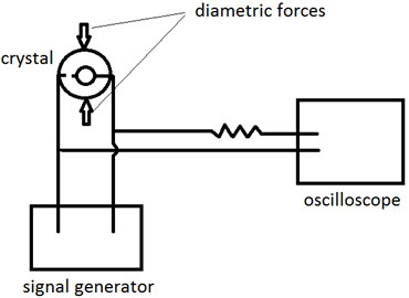
When the frequency of the output signal of the signal generator becomes close to the resonance frequency of the crystal, the resonance is occurred. At the resonance state, the crystal resonator serves as a pure resistor. Thus, the output signal of the signal generator can be seen at oscilloscope without amplitude and phase shift. If the frequency of the signal generator be far from the resonance frequency, the amplitude of the output signal observed in the oscilloscope will be smaller than the input signal.
The resonance frequency of the crystal may be changed due to external perturbations like change of the temperature or application of the external forces and accelerations. In this condition, by changing the frequency of the signal generator and tracking the maximum amplitude signal in the oscilloscope, the new resonance frequency can be measured.
In this measurement system, the oscilloscope probes and wiring system introduce a load capacitance to the resonator. The load capacitance is parallel to the static capacitance C0. Thus the measured resonance frequency is parallel resonance frequency of the crystal, and relates to the series resonance frequency by Eq. (7).
3.2. Experimental study
A square AT-cut quartz resonator is prepared with the length of 8 mm and the thickness of 0.46 mm with series thickness shear resonance frequency of 3.578545 MHz. This frequency was obtained by a standard crystal impedance meter. When the crystal introduced to the measuring system, the parallel resonance frequency of 3.57862 MHz is demonstrated. Therefore, for our measuring system upon Eq. (7), we obtain:
To perform the force-frequency test, the crystal is introduced to the loading fixture (see Fig. 4).
Fig. 4The loading fixture of quartz resonator
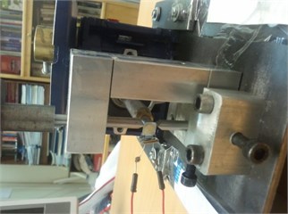
The compressive force is applied by the loading weights on the top side of the resonator via a movable rod having a wedge-shaped tip while another rod supported the sample on its bottom side. The weight of the rod was included in the total weight. The frequency of the crystal is measured before and after the loading, and the frequency shift is calculated. In our experiment, the maximum loading is 180 gr. This loading leads to the parallel resonance frequency shift of about 20 Hz in the crystal. By substituting the calculated value of from Eq. (8) into Eq. (7), the series resonance frequency shift for this experiment is obtained as:
As can be seen, the difference between series and parallel resonance frequency shifts is very small and is negligible in most of applications. For example, in quartz resonator pressure sensors, the series resonance frequency shift as high as 3000 ppm has been reported. [15] For this case, by applying Eq. (9), the parallel resonance frequency shift of about 3000.8 ppm will be measured, which is steel very close to the series resonance frequency shift.
4. Finite element modeling of the force-frequency effect
Along the experimental study, a finite element code is developed to investigate the force-frequency effect in AT-Cut quartz, using multi-physics software COMSOL 4.3.
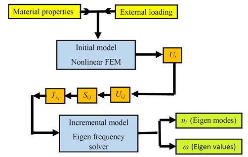
The analysis of the force-frequency effects in piezoelectric resonators belongs to the general theory of incremental elastic deformations superimposed on initial finite deformations. In this theory, the crystal is assumed to be in three states [2]. At the beginning, the crystal is in a natural state, and experience no displacement, strain, or stress. At initial state, the body is subjected to mechanical deformations due the application of diametric forces. At final state, the body is subjected to a small-amplitude vibration in addition to the mechanical deformations being imposed on the initial state. Following this procedure, our model includes two sub-models, the initial model and the incremental model. These two sub-models link three distinct sequential states of the quartz resonator. By employing the Lagrangian formulation, the displacements of all three states are referred to a single reference frame corresponding to the natural state of the resonator.
The initial model solves for the displacement, strain, and stress due to the external loading of the resonator. This model does not, however, contain the frequency response due to piezoelectrically driven vibrations, so no piezoelectric factor is included in the initial model [17]. The initial stresses, strains, and displacements, which can be derived by the stationary study of quartz in the initial model, are considered as the incremental model inputs.
The incremental model solves for the incremental response of the resonator, including only the displacement, strain, and stress of piezoelectric vibrations. The final state of the resonator is then defined as the superposition of the initial and incremental response of the resonator. Also, the incremental model uses an eigen-frequency solver, to obtain the resonant frequencies [3]. The simulation process is laid out in Fig. 5.
Fig. 5The algorithm for FE modelling of force-frequency effect
Since the quartz crystals have anisotropic characteristics, and the force-frequency effect arise from non-linear elastic behavior of quartz, the governing equations are non-linear and they cannot be implemented using the default feature of the FEA software [18, 19]. Therefore, the whole governing equations and boundary conditions are converted to weak-form expressions and launched into the finite element software. The necessary material constants of AT-Cut quartz, including second order elastic constants, and the third order elastic constants, piezoelectric constants and dielectric coefficients used in the model are based on the published values by Patel [1]. All anisotropic material characteristics are introduced to the FEM software.
4.1. Modelling the initial stress and strain distributions
In our previous paper [3], we showed that considering the anisotropic properties of quartz is vital for accurate modelling of force-frequency effect. However, the piezoelectricity may be neglected. Thus, the body was considered to be anisotropic and the initial displacements, strains, and stresses include the effects of external tractions, and do not include any piezoelectric effect [17]. Following Lee and Wang [19], and BeerWinkle [17], we used the standard nonlinear Lagrangian formulation from the theory of elasticity, to solve for the initial stress and strains. These equations are:
where is the initial Lagrangian strain, is the second Piola-Kirchhoff stress tensor, is the initial displacement gradient, is the surface traction in the boundary surfaces, and are the second- and third-order stiffness coefficients, and is surface normal vector.
These equations were introduced to the FEM software and solved for the rectangular AT-Cut quartz disc with diameter of 8 mm, thickness of 0.43 mm, which is subjected to a pair of 0.9 N and 1.8 N loads in Z crystallographic direction. The final FE model has 2158 Lagrangian quadratic elements with 164,548 degrees of freedom, as shown in Fig. 6. Since the thickness shear mode is important, in the investigation of force-frequency effect, a swept mesh is utilized to control the mesh number in thickness direction.
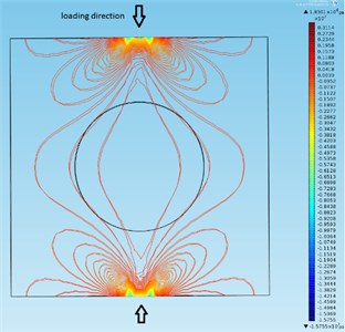
By defining two opposed forces on the center point of the upper and lower edges of the resonator, the initial stress and strain distribution is obtained on the crystal. For example, the initial stress contours (), for the 0.9 N loading state is shown in Fig. 7.
Fig. 6Meshed geometry of the resonator
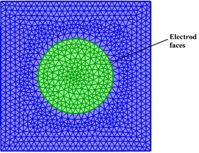
Fig. 7The initial stress contours (T11) on the rectangular disk
4.2. Solving for Eigen values
After determination of the initial fields, the governing equations for the incremental fields are solved. The final state is then governed by the superposition of the incremental displacement onto initial displacement. It should be noted that in this Lagrangian model, the external tractions having been resolved in the initial state, and the incremental displacement, strain and stress take only the effect of piezoelectric vibrations [17]. These high frequency vibrations are small deformations superposed linearly on initial finite deformation. Thus, the incremental equations can be made linear during their derivations. These equations have been derived by Wang et al, using variational principals of elasticity [20]. The incremental strains, are:
where are the incremental displacement gradients.
The incremental stress tensor, , and the incremental electric displacement are:
In above equations, , , and are the piezoelectric coupling matrix, electric field, and dielectric permittivity coefficient, respectively.
The incremental equation of motion is:
Also, the incremental surface traction equilibrium equation and Gauss’s low for an insulator material like quartz, are:
The resonance behavior of quartz is considered to be harmonic. Therefore, the motion equation will take the form of:
where, is the resonance frequency, and is the wave amplitude. As can be seen, the initial displacement gradients and stresses are appeared in the second equation of Eq. (15). Thus, the initial state must be completely solved before the final state.
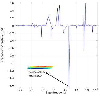
The aforementioned rectangular AT-cut quartz resonator is taken into account. Upon the experiments, a variable electric field with frequency of and amplitude voltage of 1 Volt is applied to the electrodes in COMSOL multi-physics environment. According to this electric boundary condition, the polarization direction and electric displacement vector is along the thickness of the resonator. By defining the piezoelectric coupling tensor , and dielectric permittivity tensor , from [1], and given the known values of initial stresses and displacement gradients from the initial model, the Eq. (11) to (15) are solved, and the eigen frequencies and eigen modes of the vibration are obtained. For example, the resonance spectrum of the plate under the 0.9 N compressive load and the thickness shear vibration mode are demonstrated in Fig. 8.
Fig. 8The resonance spectrum for the quartz resonator
By setting the initial fields to zero, the resonance of the disc before the loading, and the frequency shift due to the loading are obtained. Table 1 shows the fractional frequency shift, i.e. , obtained by FEM solution for the tow loading states, in comparison with experimental results. As can be seen from Table 1, the error between the fractional frequency shift obtained by FEM and the experiments is less than 1 ppm.
Table 1Fractional frequency shift obtained by experiments and finite element model
Load | Measured fractional frequency shift [ppm] | Simulated fractional frequency shift [ppm] |
0.9 N | –2.794 ppm | –2.5 ppm |
1.8N | –5.6 ppm | –5 ppm |
5. Conclusions
Force-frequency effect is one of the main reasons of frequency instability in quartz crystal resonators. Due to the modern requirement for high frequency stability in telecommunication applications, introducing appropriate methods for experimental quantification of force-frequency effect is of importance. In this article, a simple method for measurement of forcefrequency characteristics of piezoelectric resonators was introduced. For characterizing the measurement system, the series resonance frequency of the crystal was measured with a standard crystal impedance meter. Then, the parallel resonance frequency was measured with the proposed technique. It was shown that the frequency shift of the parallel resonance frequency is very close to that of the series resonance frequency. Thus, we can employ the parallel resonance frequency for measuring the force-frequency effect. Measurements were made on a square quartz crystal which was subjected to compressive loads via a loading fixture. This test was simulated by a nonlinear finite element model, and the fractional frequency shifts were calculated for two loading states. The Finite element results were compared with the experimental results, which were in close agreement.
The proposed measurement method is easier and more economic than the current measurement methods which are based on measuring the series resonance frequency of crystals. The results can assist the sensor industry, in easier measurement of the sensitivity of crystals to environmental effects like accelerations which may cause frequency instability due to force-frequency effect. Also, the numerical model can be used for design of crystal plate, the electrode, and the holder position, to achieve more frequency stability by reduction of force-frequency effect.
The measurement method may be used in sensitivity measurement and calibration of quartz resonator pressure sensors and load cells. Where, the numerical model can be applied for design and optimization of sensors to achieve higher sensitivities and smaller sizes.
References
-
PatelM. S. Nonlinear Behavior in Quartz Resonators and its Stability. Ph.D. Dissertation, Department of Civil Engineering, New Brunswick, New Jersey University, 2008.
-
Yang J. Vibration of piezoelectric crystal plates. World Scientific, Vol. 167, 2013.
-
Mohammadi M. M., Hamedi M., DaneshPajooh H. Effect of anisotropy and piezoelectricity on the force-frequency coefficient of AT-cut quartz crystals. Scientia Iranica, 2015, (in Press).
-
EerNisse E. P. Quartz resonators vs their environment: time base or sensor? Japanese Journal of Applied Physics, Vol. 40, Issue 5S, 2001, p. 3479.
-
Bottom V. E. Second Semi-Annual Technical Report on Contract No. W-36-039-SC-32083, 1947, p. 27.
-
Gerber E. A., SykesR. A. State of the art quartz crystal units and oscillators. Proceedings of the IEEE, Vol. 54, Issue 2, 1996, p. 103-116.
-
Gerber E. A., Miles M. H. Reduction of the frequency-temperature shift of piezoelectric resonators by mechanical stress. Proceedings of the IRE, Vol. 49, Issue 11, 1961, p. 1650-1654.
-
Ratajski J. M. Force-frequency coefficient of singly rotated vibrating quartz crystals. IBM Journal of Research and Development, Vol. 12, Issue 1, 1968, p. 92-99.
-
DauwalterC. R. The temperature dependence of the force sensitivity of AT-cut quartz crystals. 26th Annual Symposium on Frequency Control, 1972, p. 108-112.
-
EerNisseE. P. Temperature dependence of the force frequency effect for the AT, FC, SC and rotated X-Cuts. 34th Annual Symposium on Frequency Control, 1980, p. 426-430.
-
Wang Z., Huizhong Z., Yonggui D., Guanping F. A thickness-shear quartz resonator force sensor with dual-mode temperature compensation. Sensors Journal, Vol. 3, Issue 4, 2003, p. 490-496.
-
Asakura A., Toshio F., Fumihito A. Design, fabrication and characterization of compact force sensor using AT-cut quartz crystal resonators. IEEE/RSJ International Conference, Intelligent Robots and Systems, 2008, p. 506-511.
-
Arnau A. Piezoelectric Transducers and Application. Springer, New York, 2004.
-
Bottom V. E. Introduction to Quartz Crystal Unit Design. Van Nostrand Reinhold, 1982.
-
Clayton L. D., EerNisseE. P. Quartz thickness-shear mode pressure sensor design for enhanced sensitivity. IEEE Transactions on Ultrasonics, Ferroelectrics, and Frequency Control, Vol. 45, Issue 5, 1998, p. 1196-1203.
-
EerNisseE. P., WigginsR. B. Review of thickness-shear mode quartz resonator sensors for temperature and pressure. IEEE Sensors Journal, Vol. 1, Issue 1, 2001, p. 79-87.
-
BeerwinkleA. D. Nonlinear Finite Element Modeling of Quartz Crystal Resonators. M.S. Thesis, Department of Mechanical Engineering, Oklahoma State University, Stillwater, USA, 2011.
-
Tiersten H. F. On the nonlinear equations of thermo-electroelasticity. International Journal of Engineering Science, Vol. 9, Issue 7, 1971, p. 587-604.
-
Lee P. C. Y., Wang Y. S., Markenscoff X. High-frequency vibrations of crystal plates under initial stresses. Journal of the Acoustical Society of America, Vol. 57, Issue 1, 1975, p. 95-105.
-
Wang Z., Huizhong Z., Yonggui D., Jinsong W., Guanping F. Force-frequency coefficient of symmetrical incomplete circular quartz crystal resonator. IEEE Transactions on Ultrasonics, Ferroelectrics, and Frequency Control, Vol. 48, Issue 5, 2001, p. 1471-1478.
