Abstract
A finite element model of a slant cracked rotor system attached with two disks is presented. A slant crack model is adopted to simulate time-varying stiffness caused by shaft crack. Two types of bearing force (linear and nonlinear bearing forces) are used for simulating the bearing. This study focuses on the effects of eccentric phase differences of two disks on the nonlinear responses of the rotor-bearing system under steady-state process (constant rotating speed) and run-up process. The results show that for the lateral vibration, the superharmonic resonance phenomenon related to the first bending critical speed can be observed under linear bearing forces; however, it is almost unseeable under nonlinear bearing forces. For the torsional vibration, the superharmonic resonance phenomena related to the first torsional natural frequency appear under linear and nonlinear bearing forces. Large eccentric phase differences of two disks can decrease the rotor vibration and restrain the oil-film instability, and the angular acceleration can restrain the oil-film instability due to the tangential inertia force. Moreover, the large torsional amplitude of the second harmonic frequency can also be identified as a typical feature during run-up.
1. Introduction
In rotating machinery, the fatigue shaft crack may be appearing due to manufacturing flaws, corrosive or thermal loading, which can be identified as the main cause of many catastrophic failures. The local crack will introduce local flexibilities, which has a great influence on the vibration behaviors of the rotor system. A large amount of researches on dynamics of cracked rotor has been performed, and work in this area is still continuing. The early researches on crack can date back to the 1970s. Some review papers summarized the main research progress, such as Wauer[1], Gasch [2] and Dimarogonas [3]. Recent researches mainly focused on the crack breathing mechanism, different modeling approaches for the cracked rotor element, cracked shaft vibrations and crack identification methods in [4-6].
Generally, cracks propagate in surfaces with are roughly planar and perpendicular to the rotating axis of the shaft. However, the crack may also propagate along a helicoidal path under large torque loading and these cracks are referred in the literature as helicoidal or slant cracks [5]. Assuming that the slant crack opens and closes synchronously with torsional excitation frequency, Ichimonji et al. [7, 8] firstly analyzed the dynamic characteristics of a simple rotor by a qualitative study. Sekhar and Prasad [9] established a finite element model of a rotor-bearing system for flexural vibrations by including a shaft having a slant crack. In their model, a flexibility matrix for a slant crack and later the stiffness matrix of a slant cracked element were developed. Prabhakar et al.[10] studied vibration characteristics of a slant-cracked rotor passing through its flexural critical speed by using finite element method for flexural vibrations and analyzed the transient response of a cracked rotor by applying an unbalance force and a harmonically varying torque on the rotor. Through the modeling; the dynamic analysis; and detection and monitoring techniques, Sekar et al.[11] compared the vibration behavior of rotors with the transverse crack and slant crack. Darpe[12] presented a simple Jeffcott rotor with a slant crack. In his model, the flexibility matrix of the rotor with slant crack is developed and the stiffness coefficients based on the flexibility values are used in the equations of motion. In another paper [13], Darpe derived a new flexibility matrix for the slant crack that accounts for the additional stress intensity factors due to orientation of the crack compared to the transverse crack and compared the stiffness coefficients and coupled vibration response characteristics between rotor with the slant and transverse crack. Lin and Chu [14, 15] derived four motion equations of two transversal, one torsional and one longitudinal directions of a Jeffcott rotor system with a 45° slant crack on the shaft, and the main stiffnesses and coupling ones are derived based on the relationship between stress intensity factors and strain energy density function. Han et al. [16] established a finite element model of a geared rotor with slant crack and carried out the dynamic analysis of a geared rotor-bearing system with a breathing slant crack is performed. In another paper [17], by using the direct spectral method, Han et al. analyzed the forced responses of a geared rotor system with slant cracked shaft and time-varying mesh stiffness and discussed the effects of straight or slant crack and crack depth on the forced response of the system without and with torsional excitation. Liu et al. [18]compared the dynamic characteristics of rotor with bearing transverse and slant cracks by using finite element method.
A lot of researches on the rotor crack are based on rigid bearing supports, and there is less work reported on the cracked flexible rotor supported fluid film bearings [19-24]. However, the stability and dynamic characteristics of this kind of system are very important as dangerous cracks were mainly reported in rotors running on fluid film bearings. By using the eight rotordynamic coefficients to simulate the effects of journal bearing, Gomez-Mancilla et al. [19] developed an extended Jeffcott rotor on lubricated journal bearings having masses and imbalances at disc and bearings, and analyzed the orbit evolution and vibration patterns at the local resonances. Based on the same simulated method of journal bearing in [19], Sekhar [20] developed equations of motion for transient response and carried out dynamic analysis by considering the effects of fluid film bearings.
Considering the nonlinear oil-film force of journal bearing, many researchers[21-24] studied the dynamic characteristics of cracked rotor system. Meng and Gasch [21] investigated the stability and the stability degree of a flexible cracked rotor supported on different kinds of journal bearings and analyzed the influences of the crack stiffness ratio, the fixed Sommerfeld number, the gravity parameter, and the mass ratio on the system stability. Papadopoulos et al. [22]investigated the dynamic behavior of a rotor-bearing system based a continuous approach, where the shaft rotates on two journal bearings that are simulated as forces acting on the rotor. Yang and Suh[23] studied the various nonlinear responses and dynamic instabilities by a comprehensive rotor model incorporating translational and rotational inertia, bending stiffness, gyroscopic movements, and shear deformation and experiencing slow crack growth and nonlinear bearing film forces. Bachschmid and Dellupi [24]used a model-based identification procedure to identify the nonlinear forces of linearized and nonlinear oil films in two lobe journal bearings. Their presented method utilizes the linear model of the rotor and the nonlinear oil-film forces in the identification procedure.
Most of the previous work focused on the steady-state vibrations of the rotor-bearing system. However, the transient response during run-up and run-down is also important as steady-state response to detect cracks[20, 25-29]. Sekhar [20]analyzed the coast-down phenomenon caused by transverse rotor crack by considering the dissipation through the journal film and by evaluating the deceleration for each speed, and found characteristic sub-critical response peaks when the cracked rotor decelerates through its critical speed. Prabhakar et al. [28]analyzed the vibration characteristics of a slant-cracked rotor passing through its flexural critical speed by using finite element method for flexural vibrations. Sekhar [29] analyzed both start-up and run-down phenomena and compared for the same rotor for the same angular acceleration and deceleration together with the effects of crack, and extract the features of transverse cracks from the time-domain signals of rotor-bearing system by using the continuous wavelet transform (CWT).
Many literatures also showed that the unbalance has a great effect on the vibration response of the cracked rotor[19, 30-32]. Sinou [31] studied the influence of the crack-unbalance interactions and more particularly the relative orientation between the front crack and the unbalance on the vibration responses of the cracked rotor system. Cheng et al.[32] investigated the influence of nonlinear breathing of the crack and the imbalance orientation angle on the stability, critical speed and peak response of the rotor.
Based on the analysis of the above literatures, it is clear that the dynamics of an elastically supported cracked rotor is physically and fundamentally different from that supported using fluid-film bearings [23]. Although the vibration responses of the rotor system supported by fluid-film bearings have been investigated [33-41], the researches on nonlinear dynamic responses caused by crack in a rotor-bearing system supported by fluid bearings are not sufficient. On the basis of [12, 13, 33, 37], this study investigates the nonlinear dynamic characteristics induced by slant crack and linear/nonlinear bearing force in a flexible rotor system attached two disks are analyzed by using finite element method. Moreover, the study also discusses the effects of eccentric phase differences of two disks on the nonlinear responses of the rotor-bearing system under steady-state process (constant rotating speed) and run-up process.
2. Finite element model of a rotor system with a slant crack
2.1. FE model of a rotor segment with slant crack
In order to simplify the modeling process, some assumptions for the rotor crack are made as follows:
(1) A non-propagating slant crack is assumed, and the crack surfaces are assumed to be planar and smooth, and the crack thickness is ignorable, i.e., the gap between two crack surfaces is zero [42].
(2) The material properties of the cracked shaft are assumed to be linearly elastic.
A shaft segment containing a slant crack (see Fig. 1) is modeled by a Timoshenko beam element with six degrees of freedom per node. However, considering the presence of a slant crack, the stiffness matrix of the beam element needs to be modified, which is different with the usual beam element. The coupling phenomena including bending-longitudinal, bending-torsion and longitudinal-torsion have been taken into consideration to modify the stiffness matrix. Then the modified crack shaft element is fitted into the finite element assemblage of the whole rotor system.
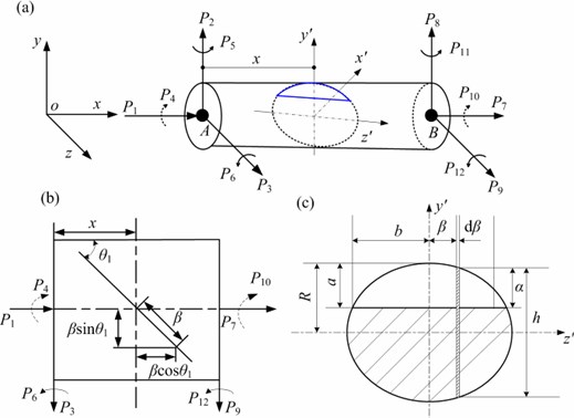
A shaft element with a slant crack having a depth of oriented at an angle of relative to the axis of the shaft is shown in Fig. 1(b) and the crack center is situated at a distance from the left end of the element. The element is loaded with shear forces , and , , bending moments , and , , axial forces and , and torsional moments and (see Fig. 1(a)). In Fig. 1(c), is the radius of the shaft; is a half of the crack width; is the depth of crack at any distance from the center along the crack edge; is the total height of the strip of width .
Based on fracture mechanics, the total strain energy is expressed as:
where and are the strain energy of the uncracked shaft element and the additional strain energy due to crack, respectively. The strain energy can be expressed as follows:
where and are the shear forces, and are the bending moments, is the torsional moment, is the axial force acting at the crack cross-section, is the modulus of rigidity, is the Young’s Modulus, is the area moment of inertia of the cross-section, is the polar moment of inertia of the cross-section and is the shear coefficient.
Fig. 1Shaft finite element: a) the crack element showing forces acting and coordinate system, b) top-view of the slant crack element, c) cross-section of slant crack
Based on the loaded forces and moments acting on the crack element (see Fig. 1), , , , , , and , the can be rewritten as follow:
The additional strain energy due to the slant crack can be expressed as:
where, , is the Poisson’s ratio. , and represent the stress intensity factors corresponding to the opening, sliding and shearing modes of crack displacement, respectively. Additionally, the detailed expressions of these stress intensity factors can be found in [12].
Assumed that and are the displacement and force, the flexibility coefficients of the slant crack element are expressed as follows:
The flexibility matrix of the slant crack element is given by:
The stiffness matrix of cracked shaft element can be written as:
where is the transformation matrix is given by:
here, is the length of the slant crack element.
2.2. Modeling of breathing behavior of the slant crack
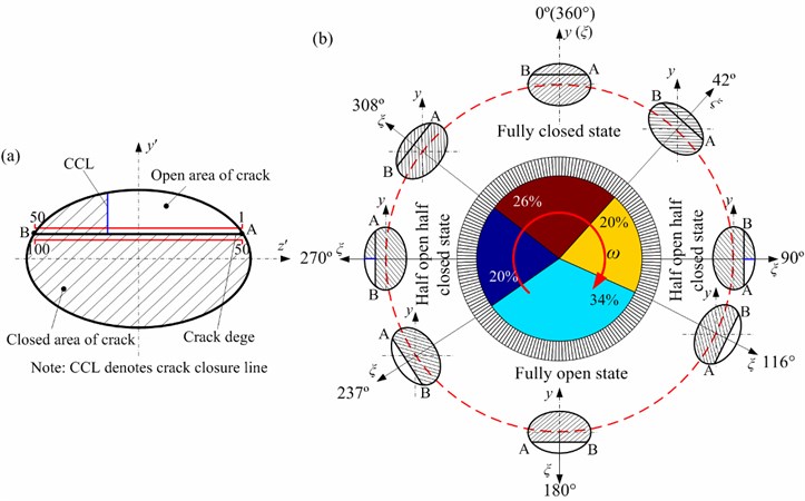
During the operation of the cracked rotor, the crack is not keeping a constant state, but changing at each instant. In practice, part of the slant crack opens and closes in different rotating angles (see Fig. 2), which is called the breathing behavior of the crack. In order to study the flexibility variation with amount of crack opening and closing, Darpe et al. [43] proposed a concept of crack closure line (CCL), as is shown in Fig. 2(a). The crack closure line is an imaginary line perpendicular to the crack edge and it separates the open and closed parts of the crack. The crack edge is divided into 50 points in this study. When the rotor system stays in a rotating state, the position of the CCL keeps changing along the crack edge as the rotor rotates anticlockwise, namely, from 1 to 50 while opening from A to B and from 50 to 100 while closing from A to B. For example, at 840 rev/min, the law of the crack breath is shown in Fig. 2b. The figure indicates that the crack breathes from fully closed state in the range of [308°, 360°]∪[0°, 42°], and opens gradually from fully closed to fully open state when 42°, 116, and thereafter fully opens at [116°, 237°], then closes gradually from fully open to fully closed state at 237°, 308°.
The value of the stress intensity factors () at the crack front is applied to describe the crack breathing behavior, which is used for confirming critical line separating the open or closed part:
The sign of is employed to indicate the state of crack along the crack edge. If the sign of at any point along the crack edge is negative, it indicates compressive stress at that point, and hence the crack is assumed closed there. If the sign of is positive, it indicates tensile stress and the crack stays in open state.
According to the sign of , the crack closure line position can be ascertained. Furthermore, the integration limits responsible for flexible matrix coefficients can also be determined. Hence, the time-varying stiffness matrix in rotating coordinates is obtained. Through using global transformation matrix , the is transformed from the rotating coordinate to the in stationary coordinate. is assembled using the elemental coordinate transformation matrix , which is shown as:
where is the angle of rotation:
Fig. 2Variation of crack closure line position with angular position of rotor
2.3. FE model of the rotor-bearing system
A rotor-bearing system, attached with two identical disks and supported by two bearings, is shown in Fig. 3. In order to study the rotor-bearing system efficiently, the FE model of the rotor-bearing system is simplified according to the following assumptions:
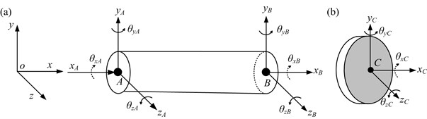
(a) The shaft is divided into 10 Timoshenko beam elements and 11 nodes. Every node has six degrees of freedom as is shown in Fig. 4(a). The slant crack occurs at the fifth element.
(b) The rigid disks are simulated by lumped mass elements which are superimposed upon the corresponding shaft nodes (see Fig. 4(b)). In Fig. 4(b), is the orientation of unbalance of disk 1 relative to the crack direction () and is the eccentric phase difference between the unbalance of disk 1 () and the unbalance of disk 2 ().
These elements are simulated by the mass , the diametral and polar moments of inertia (, and ), meanwhile the gyroscopic effects of the disks are also considered.
(c) The left and right bearings are identical and simulated by linear bearing forces and nonlinear oil-film forces presented in [33].
The general displacement vector of a beam element for the shaft can be expressed as:
where the superscript stands for an element.
The general displacement vector of a rigid disk is given as:
Fig. 3Schematic diagram and physical dimensions of the simplified rotor-bearing system
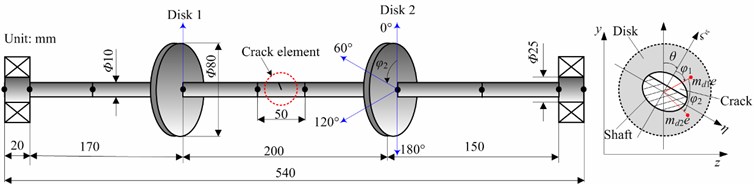
Fig. 4FE model schematics of a shaft element and rigid disk
The mass, stiffness and gyroscopic matrices of shaft and disk elements are denoted as , , and , , respectively. The detailed expressions for these matrices can be found in [44].
Considering the effects of the bearing oil-film forces, unbalance exciting force, the rotor gravity, the dynamic equations of the rotor-bearing system with slant crack can be written as:
where , , and are the mass, stiffness, damping and gyroscopic matrices of the system in stationary coordinates. denotes the displacement vector. represents the excitation force vector due to the disk unbalance, here only the disk unbalances are applied at nodes 4 and 7. denotes the oil-film force vectors of the sliding bearings at nodes 1 and 10 (see Fig. 2). denotes the static gravitational force vector in direction.
The nodal force vectors at nodes 4 (disk 1) and 7 (disk 2) are given as follows:
where , and denote the node force, torque and bending moment. The subscripts , , denote the directions of forces, torque and bending moment and the number subscript denotes node. is the angle of rotation. is the initial angular velocity, in this paper 10 rad/s.
It should be noted that only stiffness matrix is constantly updated, usually after every degree of rotation. The mass and damping matrices are assumed constant. Rayleigh damping form is applied and obtained by the following formula [37]:
where and are the first and second natural frequencies (rev/min); and are the first and second modal damping ratios, respectively. In this paper, 0.005 and 0.01.
Two methods for modeling the supporting forces of bearing are proposed, one is linear stiffness-damping model, and the other is nonlinear oil-film force model based on short bearing theory. The specific demonstrations are as follows:
2.3.1. Linear bearing force model
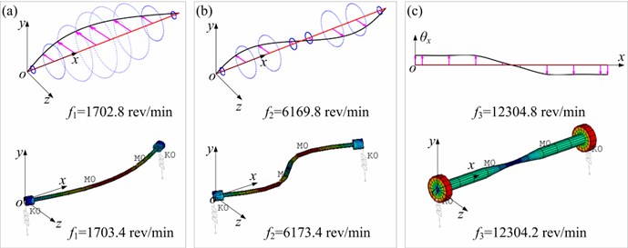
Only the stiffness and damping coefficients terms in horizontal (-coordinate) and vertical (-coordinate) directions are considered, while the cross stiffness and damping terms are neglected. The horizontal and vertical stiffness terms have equal values (2.5×10⁷ N/m), and the horizontal and vertical damping terms , , , have equal values (2.1×10³ N∙s/m). Based on the simulation data above, the first and second bending natural frequencies of the system () are 28.38 and 102.83 Hz, and the first torsional frequency () is 205.08 Hz. In order to verify the model validly, FE model in ANSYS is also established (see Fig. 5). In ANSYS software, the rotor shaft is simulated by using BEAM188 element; the rigid disks are modeled as concentrated masses by using MASS21 element; two identical bearings are modeled by using COMBI214 elements. The results in Fig. 5 indicate that the first three natural frequencies and mode shapes obtained by two models are almost exactly the same.
Fig. 5The comparison of mode shapes in bending and torsional directions between this paper and ANSYS software
2.3.2. Nonlinear bearing force (oil-film force) model
According to the short bearing theory, the nonlinear oil-film force vectors at nodes 1 and 10 are expressed as follows:
where and are dimensionless oil-film forces in horizontal and veridical directions, and is as follow:
here, , , and are oil viscosity, bearing length, journal diameter and mean radial clearance, respectively. The detailed expressions of and can be found in [33].
3. Vibration responses of the rotor system with slant crack under linear and nonlinear bearing forces
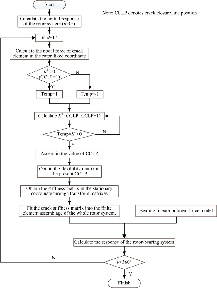
Model parameters used in numerical simulation are shown in Table 1. In this section, in order to indicate the effects of the simplified forms of bearing on the vibration responses of the rotor system with slant crack, two simplified bearing models: linear and nonlinear bearing forces are compared under steady-state (0 rad/s2) and transient (10 rad/s2) conditions. The detailed simulation cases are listed in Table 2. The detailed flow chart for vibration response calculation of a rotor-bearing system with slant crack is displayed in Fig. 6.
Table 1Model parameters
Types | parameters |
Nonlinear bearing | 0.04 Pa·s, 10 mm, 25 mm, 0.03 mm |
Linear bearing | 25 MN/m, 2.1 kN·s/m |
disk | 0.5919 kg, 4.735×10⁻⁴ kg·m2, 2.478×10⁻⁴ kg·m2 |
Unbalance | 118.38 g·mm |
Crack | 45°, crack depth ratio |
Material | 210 GPa, 7850 kg/m3, 0.3 |
3.1. Vibration responses in horizontal and torsional directions under linear bearing forces
3.1.1. Case 1: 0 rad/s2 under linear bearing forces
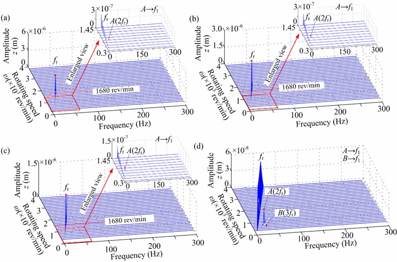
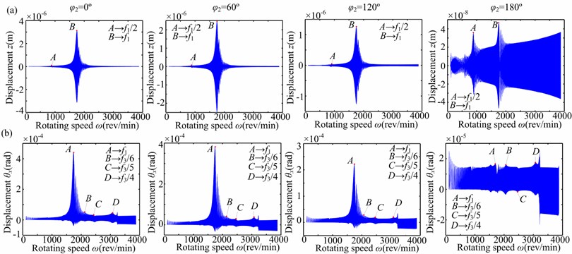
With the increasing eccentric phase difference of two disks , spectrum cascades of the right journal (node 10) in horizontal and torsional directions under 0 rad/s2 and 0.3 are shown in Figs. 7 and 8, which describe the steady-state unbalance response at rotating speed ranging from 360 rev/min to 3840 rev/min in steps of 120 rev/min. For the sake of clarity, some enlarged views from 360 rev/min to 1440 rev/min are also provided. These figures show the following dynamic phenomena:
1) The horizontal vibration responses in Fig. 7 indicate that the amplitude of the rotating frequency component () reduces with the increasing . By the enlarged views, it is clear that the distinctive superharmonic resonance phenomena can be observed at the 1/2nd first bending critical speed 840 rev/min). Under the out-of-phase eccentricities of two disks (180°), superharmonic resonance can also observed at 600 rev/min, which is close to the 1/3rd first bending critical speed (560 rev/min).
Fig. 6Flow chart for vibration response calculation of a rotor-bearing system with slant crack
2) The torsional vibration responses in Fig. 8 indicate that the distinctive superharmonic resonance phenomena appear near 2400 rev/min and 3200 rev/min, which is close to 1/5th and 1/4th first torsional natural frequencies (2460 rev/min and 3075 rev/min). With the increasing , superharmonic resonance at 1/7th and 1/6th first torsional natural frequencies can also observed, such as at 120° and 180° (see Figs. 8(c) and 8(d)).
Table 2A description of simulation
Simplified bearing forms | Cases | Angular acceleration | Crack parameters | Unbalance parameters | Bearing parameters | Figures concerned |
Linear bearing force | Case 1 | 0 rad/s2 | 0.3, 0° | 0°, 60°, 120°, 180º | 25 MN/m, 2.1 kN·s/m | Figs. 7, 8 |
Case 2 | 10 rad/s2 | , 0° | 0°, 60°, 120°, 180º | 25 MN/m, 2.1 kN·s/m | Figs. 9-11 | |
Nonlinear bearing force | Case 3 | 0 rad/s2 | , 0° | 0°, 60°, 120°, 180° | 0.04 Pa·s, 10 mm, 25 mm, 0.03 mm | Figs. 12,13 |
Case 4 | 10 rad/s2 | 0.3, 0° | 0°, 60°, 120°, 180° | 0.04 Pa·s, 10 mm, 25 mm, 0.03 mm | Figs. 14-16 |
Fig. 7Spectrum cascades in horizontal direction under linear bearing condition (case 1: aac= 0 rad/s2, a-= 0.3): a) φ2= 0°, b) φ2= 60°, c) φ2= 120°, d) φ2= 180°
3.1.2. Case 2: 10 rad/s2 under linear bearing forces
Spectrum cascades of the right journal (node 10) in horizontal and torsional directions under 10 rad/s2 and 0.3 are indicated in Figs. 9, 10 and 11, which describe the transient unbalance response at rotating speed ranging from 140 rev/min to 3830 rev/min in steps of 90 rev/min. For the sake of clarity, some enlarged views from 340 rev/min to 1490 rev/min are also provided. These figures show the following dynamic phenomena:
1) The horizontal vibration responses in Fig. 9(a) and 10 indicate that angular acceleration has some effect on the first bending critical speed in comparison with the steady-state process (0 rad/s2) because of the tangential inertia force caused by run-up process, and the superharmonic resonance phenomena also appear at the 1/2nd first bending critical speed.
Fig. 8Spectrum cascades in torsional direction under linear bearing condition (case 1: aac= 0 rad/s2, a-= 0.3): a) φ2= 0°, b) φ2= 60°, c) φ2= 120°, d) φ2= 180°
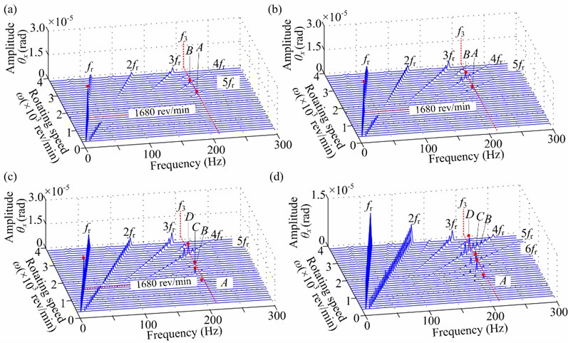
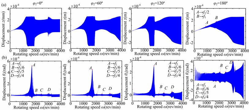
Fig. 9Time responses through its critical speed under linear bearing condition (aac= 10 rad/s2, a-= 0.3): a) horizontal direction z, b) torsional direction θx. Note: the subgraphs from left to right are φ2= 0°, 60°, 120° and 180°, respectively
2) The torsional vibration responses in Fig. 9(b) and 11 indicate that the distinctive superharmonic resonance phenomena appear near the 1/5th and 1/4th first torsional natural frequencies. When the rotor vibration amplitude is small, the superharmonic resonances near the 1/6th and 1/7th first torsional natural frequencies are also obvious (see Fig. 11(d)). Moreover, the large torsional amplitude of 2 is also a typical feature at 0°, 60° and 120° during run-up process (see Fig. 11(a), 11(b) and 11(c)).
Fig. 10Spectrum cascades in horizontal direction under linear bearing condition (aac= 10 rad/s2, a-= 0.3): a) φ2= 0°, b) φ2= 60°, c) φ2= 120°, d) φ2= 180°
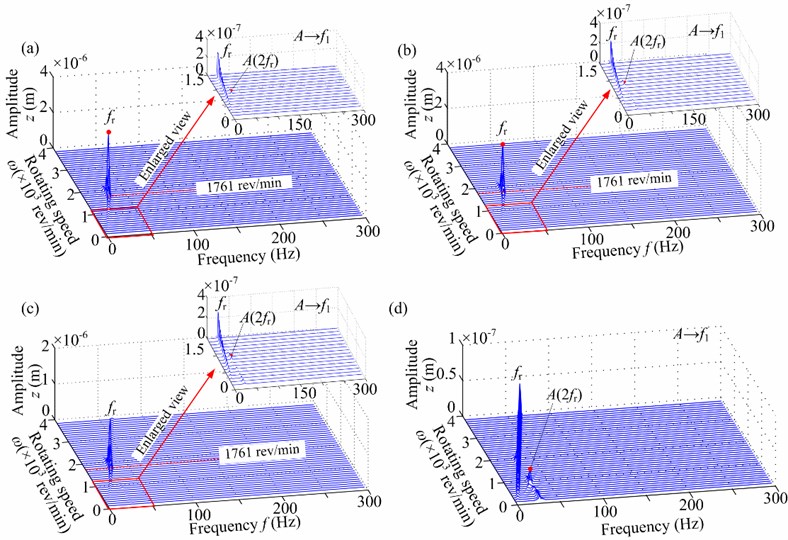
Fig. 11Spectrum cascades in torsional direction through its critical speed under linear bearing condition (aac= 10 rad/s2, a-= 0.3): a) φ2= 0°, b) φ2= 60°, c) φ2= 120°, d) φ2= 180°
3.2. Vibration responses in horizontal and torsional directions under nonlinear bearing forces
3.2.1. Case 3: 0 rad/s2 under nonlinear bearing forces
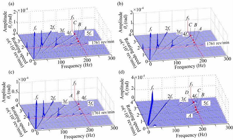
Applying the nonlinear bearing force model (Eq. (18)), spectrum cascades of the right journal (node 10) in horizontal and torsional directions under 0 rad/s2 and 0.3 are shown in Figs. 12 and 13, which describe the steady-state unbalance response at rotating speed ranging from 360 rev/min to 3840 rev/min in steps of 120 rev/min. Some dynamic phenomena are described as follows:
1) The horizontal vibration responses in Fig. 12 show that the lateral vibration is mainly affected by nonlinear oil-film force. Typical oil-film instability features, such as half-speed whirl and subharmonic components of /2 and 3/2, can be observed in Fig. 12(a) and 12(b). Superharmonic resonance phenomena disappear compared with those under linear bearing force.
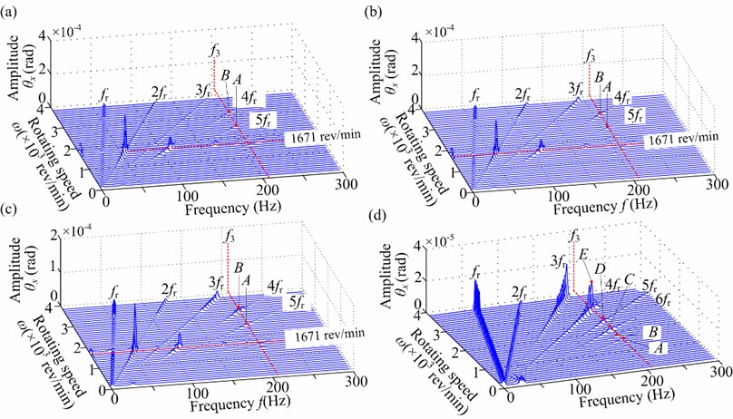
2) The torsional vibration responses in Fig. 13 display that the subharmonic components of /2 and 3/2 caused by nonlinear oil-film forces still exist. This also demonstrates the lateral-torsional coupling vibration phenomenon caused by slant crack. Moreover, the distinctive superharmonic resonance phenomena related to the first torsional natural frequency can also observed, which is similar to the laws under linear bearing force.
Fig. 12Spectrum cascades in horizontal direction under nonlinear bearing condition (aac= 0 rad/s2, a-= 0.3): a) φ2= 0°, b) φ2= 60°, c) φ2= 120°, d) φ2= 180°
3.2.2. Case 4: 10 rad/s2 under nonlinear bearing forces
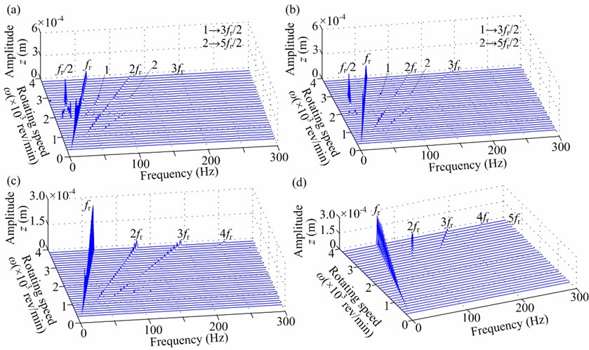
Spectrum cascades of the right journal (node 10) in horizontal and torsional directions under 10 rad/s2 and 0.3 are shown in Figs. 14, 15 and 16, which describe the transient unbalance response. In the figure, denotes the first mode whip frequency. Figs. 14(a) and 15 show that the oil-film features are restrained during run-up due to the tangential inertia forces and multiple frequency components 2, 3 and 4 become dominant. Fig. 14(b) and 16 display that the oil-film features appear and the superharmonic resonance phenomena related to the first torsional natural frequency can also observed.
Fig. 13Spectrum cascades in torsional direction under nonlinear bearing condition (aac= 0 rad/s2, a-= 0.3): a) φ2= 0°, b) φ2= 60°, c) φ2= 120°, d) φ2= 180°
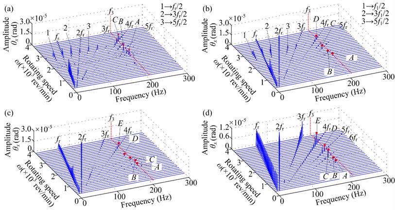
Fig. 14Time response through its critical speed under nonlinear bearing condition (aac= 10 rad/s2, a-= 0.3): a) horizontal direction z, b) torsional direction θx. Note: the subgraphs from left to right are φ2= 0°, 60°, 120° and 180°, respectively
4. Conclusions
The nonlinear dynamic characteristics induced by slant crack and linear/nonlinear bearing force in a flexible rotor system attached two disks, are analyzed by using finite element method. The effects of eccentric phase differences of two disks on the nonlinear responses of the rotor-bearing system are analyzed under steady-state process (constant rotating speed) and run-up process. Some conclusions are summarized as follows:
1) The lateral vibration shows that superharmonic resonance phenomenon related to the first bending critical speed can be observed under linear bearing forces. However, it is almost unseeable under nonlinear bearing forces. In the analyzed frequency range, the superharmonic resonance near the 1/2nd first bending critical speed is obvious.
2) Under linear and nonlinear bearing forces, the torsional vibration all indicates that the superharmonic resonance phenomena related to the first torsional natural frequency appear. In the analyzed frequency range, the superharmonic resonances near the 1/5th and 1/4th first torsional natural frequencies are obvious, which can be identified as distinctive features to diagnose the slant crack.
Fig. 15Spectrum cascades in horizontal direction under nonlinear bearing condition (aac= 10 rad/s2, a-= 0.3): a) φ2= 0°, b) φ2= 60°, c) φ2= 120°, d) φ2= 180°
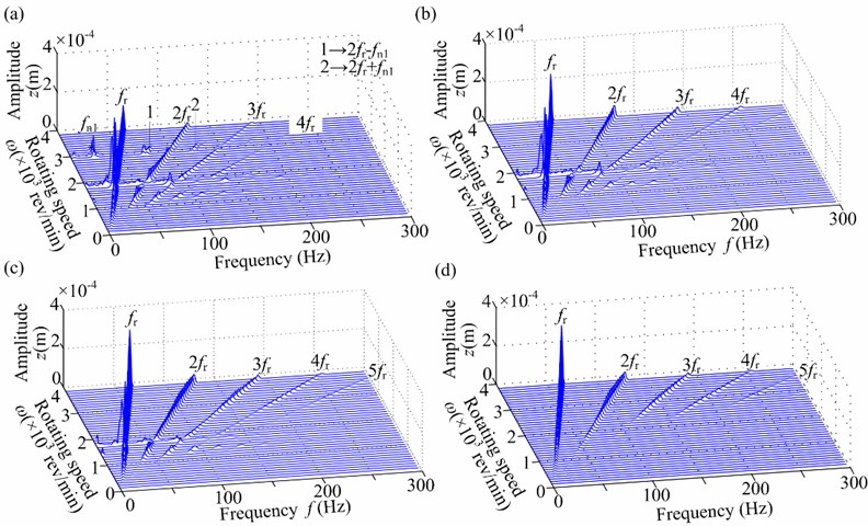
Fig. 16Spectrum cascades in torsional direction under nonlinear bearing condition (aac= 10 rad/s2, a-= 0.3): a) φ2= 0°, b) φ2= 60°, c) φ2= 120°, d) φ2= 180°
3) The eccentric phase difference of two disks and angular acceleration during run-up have some effects on the vibration of the rotor system with slant crack. Large can decrease the rotor vibration and restrain the oil-film instability. The angular acceleration can restrain the oil-film instability due to the tangential inertia force. Moreover, the large torsional amplitude of the second harmonic frequency (2) is also a typical feature during run-up.
In this study, the vibration responses of cracked rotor systems are simulated by numerical simulation. In this practical engineering, the measured crack signals are usually contaminated by noise, in my future work, the effects of noise on the feature extraction of crack fault will be focused by removing the noise signal using wavelet analysis.
References
-
Wauer J. On the dynamics of cracked rotors: a literature survey. Applied Mechanics Reviews, Vol. 43, Issue 1, 1990, p. 13-17.
-
Gasch R. A. A survey of the dynamic behavior of simple rotating shaft with a transverse crack. Journal of Sound and Vibration, Vol. 160, Issue 2, 1993, p. 313-332.
-
Dimarogonas A. D. Vibration of cracked structures: a state of the art review. Engineering Fracture Mechanics, Vol. 55, Issue 5, 1996, p. 831-875.
-
Papadopoulos C. A. The strain energy release approach for modeling cracks in rotors: a state of the art review. Mechanical Systems and Signal Processing, Vol. 22, Issue 4, 2008, p. 763-789.
-
Bachschmid N., Pennacchi P., Tanzi E. Cracked Rotors: a Survey on Static and Dynamic Behavior Including Modelling and Diagnosis. Springer-Verlag, Berlin, Heidelberg, 2010.
-
Chandan K., Rastogi V. A brief review on dynamics of a cracked rotor. International Journal of Rotating Machinery, Vol. 2009, 2010, p. 758108.
-
Ichimonji M., Watanabe S. The dynamics of a rotor system with a shaft having a slant crack. JSME International Journal, Series 3: Vibration, Control Engineering, Engineering for Industry, Vol. 31, Issue 4, 1988, p. 712-718.
-
Ichimonji M., Kazao Y., Watanabe S., Nonaka S. The dynamics of a rotor system with a slant crack under torsional vibrations. Proceedings of the International Mechanical Engineering Congress and Exposition, Chicago (IL), Vol. 192, 1994, p. 81-90.
-
Sekhar A. S., Prasad P. B. Dynamic analysis of a rotor system considering a slant crack in the shaft. Journal of Sound and Vibration, Vol. 208, Issue 3, 1997, p. 457-473.
-
Prabhakar S., Sekhar A. S., Mohanty A. R. Transient lateral analysis of a slant cracked rotor passing through its flexural critical speed. Mechanism and Machine Theory, Vol. 37, Issue 9, 2002, p. 1007-1020.
-
Sekhar A. S., Mohanty A. R., Prabhakar S. Vibrations of cracked rotor system: transverse crack versus slant crack. Journal of Sound and Vibration, Vol. 279, Issue 3, 2005, p. 1203-1217.
-
Darpe A. K. Dynamics of a Jeffcott rotor with slant crack. Journal of Sound and Vibration, Vol. 303, Issue 1, 2007, p. 1-28.
-
Darpe A. K. Coupled vibrations of a rotor with slant crack. Journal of Sound and Vibration, Vol. 305, Issue 1, 2007, p. 172-193.
-
Lin Y. L., Chu F. L. Numerical and experimental investigations of flexural vibrations of a rotor system with transverse or slant crack. Journal of Sound and Vibration, Vol. 324, Issue 1, 2009, p. 107-125.
-
Lin Y. L., Chu F. L. The dynamic behavior of a rotor system with a slant crack on the shaft. Mechanical Systems and Signal Processing, Vol. 24, Issue 2, 2010, p. 522-545.
-
Han Q. K., Zhao J. S., Chu F. L. Dynamic analysis of a geared rotor system considering a slant crack on the shaft. Journal of Sound and Vibration, Vol. 331, Issue 26, 2012, p. 5803-5823.
-
Han Q. K., Zhao J. S., Lu W. X., et al. Steady-state response of a geared rotor system with slant cracked shaft and time-varying mesh stiffness. Communications in Nonlinear Science and Numerical Simulation, Vol. 19, Issue 4, 2014, p. 1156-1174.
-
Liu C. L., Xie P. R., Zhou S. P., et al. Dynamics characteristics of rotor with breathing crack using finite element method. Journal of Vibration, Measurement and Diagnosis, Vol. 31, Issue 2, 2011, p. 185-189.
-
Gomez-Mancilla J., Sinou J., Nosov V. R. The influence of crack-imbalance orientation and orbital evolution for an extended cracked Jeffcott rotor. Comptes Rendus Mecanique, Vol. 332, Issue 12, 2004, p. 955-962.
-
Sekhar A. S. Detection and monitoring of crack in a coast-down rotor supported on fluid film bearings. Tribology International, Vol. 37, Issue 3, 2004, p. 279-287.
-
Meng G., Gasch R. Stability and stability degree of a cracked flexible rotor supported on journal bearings. Journal of Vibration and Acoustics, Vol. 122, Issue 2, 2000, p. 116-125.
-
Papadopoulos C. A., Chasalevris A. C., Nikolakopoulos P. G. Cracked continuous rotors vibrating on nonlinear bearings. IUTAM Symposium on Emerging Trends in Rotor Dynamics, Springer Netherlands, 2011, p. 469-478.
-
Yang B. Z., Suh C. S. On fault induced nonlinear rotary response and instability. International Journal of Mechanical Sciences, Vol. 48, Issue 10, 2006, p. 1103-1125.
-
Bachschmid N., Dellupi R. Nonlinear behaviour of oil film bearings and its relevance in force identification procedures. International Gas Turbine and Aeroengine Congress and Exhibition, Vol. 4, 1997.
-
Sekhar A. S., Prabhu B. S. Transient Analysis of a cracked rotor passing through the critical speed. Journal of Sound and Vibration, Vol. 173, Issue 3, 1994, p. 415-421.
-
Plaut R. H., Andruet R. H., Suherman S. Behaviour of a cracked rotating shaft during passage through a critical speed. Journal of Sound and Vibration, Vol. 173, Issue 5, 1994, p. 577-589.
-
Sekhar A. S., Prabhu B. S. Condition monitoring of cracked rotors through transient response. Mechanism and Machine Theory, Vol. 33, Issue 8, 1998, p. 1167-1175.
-
Prabhakar S., Sekhar A. S., Mohanty A. R. Transient lateral analysis of a slant-cracked rotor passing through its flexural critical speed. Mechanism and Machine Theory, Vol. 37, Issue 9, 2002, p. 1007-1020.
-
Sekhar A. S. Crack detection and monitoring in a rotor supported on fluid film bearings: start-up vs run-down. Mechanical Systems and Signal Processing, Vol. 17, Issue 4, 2003, p. 897-901.
-
Bachschmid N., Diana G., Pizzigoni B. The influence of unbalance on cracked rotors. IMechE Conference Vibration in Rotating Machinery, 1984, p. C304/84.
-
Sinou J. J. Detection of cracks in rotor based on the 2× and 3× super-harmonic frequency components and the crack-unbalance interactions. Communications in Nonlinear Science and Numerical Simulation, Vol. 13, Issue 9, 2008, p. 2024-2040.
-
Cheng L., Li N., Chen X. F., et al. The influence of crack breathing and imbalance orientation angle on the characteristics of the critical speed of a cracked rotor. Journal of Sound and Vibration, Vol. 330, Issue 9, 2011, p. 2031-2048.
-
Zhang W., Xu X. Modeling of nonlinear oil-film force acting on a journal with unsteady motion and nonlinear instability analysis under the model. International Journal of Nonlinear Sciences and Numerical Simulation, Vol. 1, Issue 3, 2000, p. 179-186.
-
Adiletta G., Guido A. R., Rossi C. Nonlinear dynamics of a rigid unbalanced rotor in journal bearings. Part I: theoretical analysis. Nonlinear Dynamics, Vol. 14, Issue 1, 1997, p. 57-87.
-
Jing J. P., Meng G., Sun Y., et al. On the non-linear dynamic behavior of a rotor-bearing system. Journal of Sound and Vibration, Vol. 274, Issue 3, 2004, p. 1031-1044.
-
De Castro H. F., Cavalca K. L., Nordmann R. Whirl and whip instabilities in rotor-bearing system considering a nonlinear force model. Journal of Sound and Vibration, Vol. 317, Issue 1, 2008, p. 273-293.
-
Ma H., Li H., Zhao X. Y., et al. Effects of eccentric phase difference between two discs on oil-film instability in a rotor-bearing system. Mechanical Systems and Signal Processing, Vol. 41, Issue 1, 2013, p. 526-545.
-
Ma H., Li H., Niu H. Q., et al. Nonlinear dynamic analysis of a rotor-bearing-seal system under two loading conditions. Journal of Sound and Vibration, Vol. 332, Issue 23, 2013, p. 6128-6154.
-
Ma H., Wang X. L., Niu H. Q., et al. Oil-film instability simulation in an overhung rotor system with flexible coupling misalignment. Archive of Applied Mechanics, Vol. 85, Issue 7, 2015, p. 893-907.
-
Ma H., Li H., Niu H. Q., et al. Numerical and experimental analysis of the first and second-mode instability in a rotor-bearing system. Archive of Applied Mechanics, Vol. 84, Issue 4, 2014, p. 519-541.
-
Ma H., Wang X. L., Niu H. Q., et al. Effects of different disc locations on oil-film instability in a rotor system. Journal of Vibroengineering, Vol. 16, Issue 7, 2014, p. 3248-3259.
-
Ma H., Zeng J., Lang Z. Q., et al. Analysis of the dynamic characteristics of a slant-cracked cantilever beam. Mechanical Systems and Signal Processing, Mechanical Systems and Signal Processing, Vol. 75, 2016, p. 261-279.
-
Darpe A. K., Gupta K., Chawla A. Coupled bending, longitudinal and torsional vibrations of a cracked rotor. Journal of Sound and Vibration, Vol. 269, Issue 1, 2004, p. 33-60.
-
Ma H., Yang J., Song R. Z., et al. Effects of tip relief on vibration responses of a geared rotor system. Proceedings of the Institution of Mechanical Engineers Part C: Journal of Mechanical Engineering Science, Vol. 228, Issue 7, 2014, p. 1132-1154.
About this article

We are grateful to General Scientific Research Project of Liaoning Provincial Educational Bureau (Grant No. L2014512) and Growth Support Program for Excellent Talents in Liaoning Provincial Communication College (Grant No. LNCCRC201413) for providing financial support for this work.
