Abstract
This paper is concerned with free vibration analysis of plate/shell coupled structures with two opposite edges simply supported by the method of reverberation-ray matrix. The equations of motion of the flat plate and the open circular cylindrical shell, respectively based on the classical thin plate theory and the Flügge thin shell theory, are introduced. Analytical solutions of the combination of a traveling wave form along the circumferential direction and a standing wave form along the axial direction are obtained. The method of reverberation-ray matrix is applied to derive the equation of the natural frequencies for the plate/shell coupled structures. The semi-analytical natural frequencies are obtained with the employment of the golden section search algorithm. The semi-analytical calculation results of three typical plate/shell coupled structures are presented and the results are compared with those obtained by the finite element method. The comparison shows that the calculation results obtained in this paper are of high accuracy and that the formulation presented in this manuscript are validated for free vibration analysis of plate/shell coupled structures.
1. Introduction
Thin plates and thin shells are extensively used in civil, mechanical and aeronautical engineering as well as in naval architecture and ocean engineering. Most of the practical engineering structures, such as the fuselages of aircraft, the ship hulls and the ocean platforms, etc., involve plate/shell coupled structures. The vibration behaviors of such coupled structures attract much attention from engineers in their practical designs. Quite a few experimental and analytical studies have been conducted on vibration analysis of plates and shells, but not so many researches are concerned with the plate/shell coupled structures.
Vibration of coupled structures with plate components has been studied by many researchers in the past decades. Vibration behaviors of folded plates are analyzed in literature [1-9]. Vibration characteristics of and power flow transmission through the L-shaped plate are studied in [10-20]. Vibration behaviors of box-type structures are investigated by a few researchers. Dickinson and Warburton [21] analyzed the free flexural vibrations of open and closed rectangular boxes and presented a theoretical solution using a sine series. Popplewell [22] studied the free vibration of a box-type structure and the natural frequencies and normal modes are presented. Handa [23] analyzed the in-plane vibration of box-type structures by a finite element method. By considering the spatial properties of distributed forces in terms of their Fourier components and hypothesizing that the uniform component is dominant, Fulford and Petersson [24, 25] accounted for the spatially distributed wavefield at the connections of the built-up structures and the vibratory power for the box-like structure supported by an infinite plate-like recipient were considered. Lee and Wooh [26] presented the free vibration analysis of folded structures and box beams made of composite materials using a four-noded Lagrangian and Hermite finite element that incorporates high order transverse shear deformation and rotary inertia and the significance of the high order plate theory in analyzing folded structures is enunciated. Lin and Pan studied the vibration characteristics of a box-type structure using the finite element method [27], and subsequently investigated the sound radiation characteristics of a box-type structure with the employment of the finite element and boundary element methods [28]. More recently, Chen et al. [29] developed an analytical approach to investigate the vibration behaviors of a box-type built-up structure and energy transmission through the structure.
Most of the available researches on plate/shell coupled structures are concerned with closed circular cylindrical shells with end plates. Yamada et al. [30] presented the free vibration analysis of a circular cylindrical double-shell system closed by end plates. Schlesinger [31] investigated the transmission of elastic waves from a cylinder to an attached flat plate with the wave approach. Tso and Hansen [32] also studied the transmission of vibration waves through cylinder/plate junctions. Stanley and Ganesan [33] determined the natural frequencies of cylindrical shells with a circular plate attached at arbitrary locations for various boundary conditions using the semi-analytical finite element method. Tso and Hansen [34] presented a theoretical and experimental study of the transmission of vibration through a two element structure which consists of a cylindrical shell coupled to an end plate. Wu et al. [35] analyzed the vibroacoustic coupling between a finite circular cylindrical shell closed at each end by a piece of circular plate and its enclosed cavity by using the covering-domain method, which transforms the calculation of the scattering sound field of a complicated-shaped close cavity to that of a series of simply regular-shaped close shells. Wang et al. [36] formulated a substructure approach to investigate the power flow characteristics of a plate-cylindrical shell system subject to both conservative and dissipative coupling conditions. Liang and Chen [37] investigated the natural frequencies and mode shapes for a conical shell with an annular end plate or a round end plate by means of the transfer matrix method. Subsequently, Liang et al. [38] extended the transfer matrix method to analyze a composite laminated conical-plate shell. Recently, much attentions are paid to vibration analysis of joined cylindrical, conical or spherical shells [39-50].
This paper presents an analytical formulation for the free vibration analysis of plate/shell coupled structures with two opposite edges simply supported. Firstly, the force and moment resultants in a thin plate and in an open circular cylindrical shell (OCCS) are presented and the equations of motion of the thin plate and the OCCS, respectively based on the classical thin plate theory and the Flügge thin shell theory, are introduced. Then, analytical solutions of the combination of a traveling wave form along the circumferential direction and a standing wave form along the axial direction are obtained for both of the thin plate and the OCCS with two opposite edges simply supported. Subsequently, the method of reverberation-ray matrix (MRRM) is employed to derive the equation of natural frequencies for plate/shell coupled structures and the golden section search algorithm is applied to find the semi-analytical natural frequencies of the plate/shell coupled structures. Finally, the calculation results of three typical plate/shell coupled structures are presented and the results are compared with those obtained by the finite element method.
2. Formulation
According to the classical thin plate theory and the Flügge thin shell theory, the force and moment resultants and the governing differential equations for the basic components of the plate/shell coupled structures are presented at the beginning of this section. Analytical solutions of the combination form of a traveling wave along one direction and a standing wave along the other direction are obtained for both of the thin plate and the OCCS with two opposite edges simply supported. After that, the displacements and the force and moment resultants are expressed in matrix form to derive the scattering matrix, the phase matrix and the permutation matrix, which are subsequently used to formulate the reverberation-ray matrix and to obtain the equation of natural frequencies of the plate/shell coupled structures. Finally, the golden section search algorithm is applied to find the natural frequencies of the plate/shell coupled structures.
2.1. Force and moment resultants in a plate
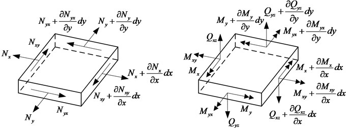
The force and moment resultants in a thin plate are shown in Fig. 1, in which the positive directions are indicated. Based on the generalized Hooke’s law, the strain-displacement relations and the stress-strain relations of the element of the thin plate, the force and moment resultants in the plate can be expressed in terms of the in-plane longitudinal, in-plane shear and out-plane displacements as follows:
where , and denote the in-plane longitudinal, in-plane shear and out-plane displacements along , and directions, respectively. and are the membrane stiffness and the bending stiffness of the plate, where is Young’s modulus, is Poisson’s ratio, and is the thickness of the plate. and denote the in-plane normal forces, and , the in-plane shear forces, and , the bending moment, and , the torsional moment, and and , the out-plane shear forces, and , represent the Kirchhoff effective shear force resultants of the first kind acting on the cross-sections perpendicular to the and directions, respectively.
Fig. 1Force and moment resultants in a thin plate
2.2. Governing differential equations and the solutions of the plate
According to the dynamic equilibrium of forces in the , and directions and the relations of the force and moment resultants with the displacements defined by Eqs. (1)-(10), the governing differential equations for the free vibration of a thin plate are obtained as follows:
where is the mass density of the plate.
Taking the Fourier transforms of Eqs. (11)-(13), the governing differential equations can be expressed in the frequency domain as:
where a tide over a symbol represents the corresponding physical quantity in the frequency domain, denotes the in-plane longitudinal wave number of the thin plate, and is the circular frequency.
With respect to a thin plate simply supported at 0 and , the in-plane longitudinal, in-plane shear, and out-plane displacements can be expressed as the series summation of the products of the modal waves along direction and the traveling waves along direction [51]:
where denotes the wave number in the direction, is the mode number and represents the length of the plate. and are respectively the wave numbers along the direction for the propagating and evanescent waves corresponding to the out-plane displacement. and are respectively the wave numbers along the direction for the propagating waves corresponding to the in-plane displacements. is the in vacuo flexural wave number of the plate. denotes the in-plane shear wave number. Wave amplitudes corresponding to the arriving wave and the departing wave are respectively indicated by and ( 1-4), in which ( 1, 2) for flexural waves of the out-plane displacement and ( 3, 4) for longitudinal waves and shear waves of the in-plane displacements.
The rotation of the normal to the mid-plane of the plate about the direction is defined as:
According to Eq. (19), the above-mentioned rotation can be expressed in frequency domain as:
Substituting Eqs. (17)-19) into the Fourier transforms of Eqs. (2), (3), (5) and (10) yields the frequency domain expressions of the force and moment resultants of the plate:
For an arbitrary axial mode number , Eqs. (17)-(19) and (21) can be expressed in matrix form as:
where denotes the displacement vector of the plate, indicates the axial mode matrix, and represents the vector of the traveling wave solutions corresponding to the displacement vector. They are presented in detail as follows:
in which and are coefficient matrices, and are amplitude vectors corresponding to the arriving wave and the departing wave, respectively. represents the phase matrix. They are presented in detail as follows:
Similarly, for an arbitrary axial mode number , Eqs. (22)-(25) can be expressed in matrix form as:
where the physical significance and expression of are the same as those presented in Eq. (28). denotes the force vector of the plate, and represents the vector of the wave solutions corresponding to the force vector. They are presented in detail as follows:
in which the physical significances and expressions of , and are the same as those defined in Eq. (29). and are coefficient matrices corresponding to the arriving wave and the departing wave of the force and moment resultants of the plate. They are presented in detail as follows:
where is a non-dimensional parameter presented in Appendix A.1.
2.3. Force and moment resultants in an open circular cylindrical shell
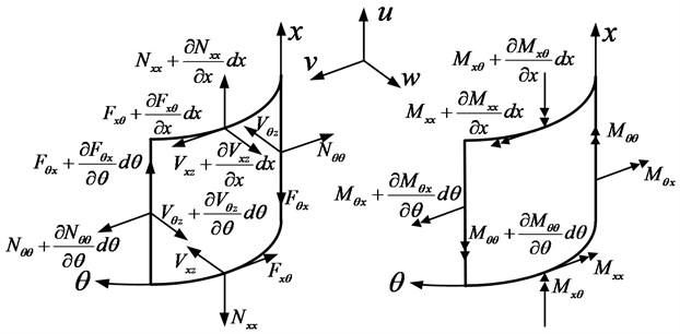
The force and moment resultants in an OCCS are shown in Fig. 2, in which the positive directions are indicated. Based on the Flügge thin shell theory, the force and moment resultants in the OCCS can be expressed in terms of the axial, circumferential and radial displacements as follows:
where , and denote the displacement components in the axial (), circumferential (), and radial () directions, respectively. and are the membrane stiffness and the bending stiffness of the shell, where is Young’s modulus, is Poisson’s ratio, is the thickness and is the radius of the shell. is a dimensionless parameter, which is related with the ratio of the shell thickness to the shell radius. , , , and are dimensionless parameters presented in Appendix A.1. and denote the in-plane normal forces, and , the in-plane shear forces, and , the bending moment, and , the torsional moment, and and , the out-plane shear forces acting on the cross-sections perpendicular to the axial and circumferential directions, respectively. Besides, and indicate the Kirchhoff effective shear force resultants of the first kind, namely, the in-plane shear force resultants, and and , the Kirchhoff effective shear force resultants of the second kind, namely, the out-plane shear force resultants acting on the cross-sections perpendicular to the axial and circumferential directions, respectively.
Fig. 2Force and moment resultants in an open circular cylindrical shell
2.4. Governing differential equations and solutions of the open circular cylindrical shell
The governing differential equations for the free vibration of an OCCS based on the Flügge thin shell theory can be written as:
Taking the Fourier transforms of Eqs. (53)-(55), the governing differential equations can be expressed in the frequency domain as:
With respect to an OCCS simply supported at 0 and , the axial, circumferential and radial displacements can be expressed as the series summation of the products of the mode waves along the axial direction and the traveling waves along the circumferential direction:
where denotes the wave number in the x direction, is the mode number and represents the length of the shell. and ( 1-4) represent wave amplitudes corresponding to the arriving wave and the departing wave, respectively. and ( 1-4) are amplitude coefficients of the axial and circumferential waves. The expressions of and are defined as follows:
and ( 1-4) are circumferential wave numbers defined by the following equation:
where ( 1-3), ( 1-2) and ( 1-10) are non-dimensional parameters presented in detail in Appendix A1 and Appendix A2.
The rotation of the normal to the mid-surface of the shell about the axial direction is defined as:
According to Eqs. (60) and (61), the above-mentioned rotation can be expressed in frequency domain as:
Meanwhile, substitution of Eqs. (59)-(61) into the Fourier transforms of Eqs. (40), (44), (50) and (52) yields the frequency domain expressions of the force and moment resultants in the OCCS:
For an arbitrary axial mode number , Eqs. (59)-(61) and (66) can be expressed in matrix form as:
where denotes the displacement vector of the OCCS, indicates the axial mode matrix and * represents the vector of the circumferential traveling wave solutions corresponding to the displacement vector. They are presented in detail as follows:
in which denotes the phase matrix. and are amplitude vectors corresponding to the arriving wave and the departing wave of the displacements of the OCCS, respectively. They are presented in detail as follows:
and and are coefficient matrices corresponding to the arriving wave and the departing wave of the displacements of the OCCS, respectively. The elements of the coefficient matrices and are listed as follows:
where 1, 2, 3, 4.
Similarly, for an arbitrary axial mode number , Eqs. (67)-(70) can be expressed in matrix form as:
where the physical significance and expression of are the same as those presented in Eq. (71). denotes the force vector of the shell, and represents the vector of the circumferential wave solutions corresponding to the force vector. They are presented in detail as follows:
in which and are coefficient matrices corresponding to the arriving wave and the departing wave of the force and moment resultants of the OCCS, respectively. The elements of the coefficient matrices and are listed as follows:
where 1, 2, 3, 4.
2.5. Equation of natural frequencies for the plate/shell coupled structures
Taking advantage of the unidirectional wave form solutions of matrix form for the thin plate obtained in Subsection 2.2 and for the OCCS obtained in Subsection 2.4, the MRRM is introduced to derive the equation of the natural frequencies of the plate/shell coupled structures.
Firstly, the plate/shell coupled structure is discretized into basic components such as flat plates and OCCSs. A dual local coordinate system is established for each of the components at both of the ends, where the cartesian coordinate for a flat plate and the circular cylindrical coordinate for an OCCS. Then, the local scattering matrix is derived according to the continuity conditions of the displacements and the equilibrium conditions of the internal forces and moments at each of the joints of the plate/shell coupled structure. Meanwhile, the local phase matrix is obtained according to the inherent relations of the harmonic waves in the dual local coordinate system. With all of the local scattering matrices and all of the local phase matrices respectively assembled into a global scattering matrix and a global phase matrix, the global scattering equation and the global phase equation are obtained. When keeping the two global amplitude vectors of the arriving wave the same, the two global amplitude vectors of the departing wave contain the same scalar state variables arranged in different sequential orders. Therefore, a permutation equation can be obtained from the relation between the two global amplitude vectors of the departing wave. Subsequently, the reverberation-ray matrix can be obtained from the simultaneous equations of the global scattering equation, the global phase equation and the permutation equation. Finally, the equation of the natural frequencies can be derived by equating the determinant of the coefficient matrix of the global amplitude vector of the departing wave to zero.
With the derivation procedure mentioned above, the equations of the natural frequencies of the three plate/shell coupled structures including a box-type structure, a racetrack cylindrical shell and a ship hull structure will be obtained in the following discussions in this subsection. However, since the three independent derivation procedures are quite similar to each other, for simplicity, one of them will be taken as an example and the other two will be omitted. Note that the solutions obtained in Subsection 2.2 are applied for flat plate components while the solutions obtained in Subsection 2.4 are applied for OCCS components.
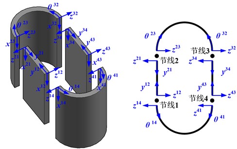
Next, the derivation for equation of the natural frequencies of the racetrack cylindrical shell shown in Fig. 3, is presented as follows.
Fig. 3Dual local coordinate systems for the racetrack cylindrical shell
2.5.1. Scattering matrix
The continuity conditions for the plate and the OCCS at Node Line 1 are presented as follows:
which can be rewritten in matrix form as:
where denotes the transfer matrix corresponding to the displacement vector at Node Line 1. The variables with superscript (, 1-4) indicate the physical quantities of the substructure bounded by Node Line and Node Line , this will not be mentioned repeatedly in the following discussions.
Since the local coordinates are established at the node lines, the phase matrix turns to be a unit matrix at the node lines. Taking into account of this condition and substituting Eqs. (26) and (71) into Eq. (90) yields:
Meanwhile, the equilibrium conditions for the plate and the OCCS at Node Line 1 are presented as:
which can be rewritten in matrix form as:
where denotes the transfer matrix corresponding to the force vector at Node Line 1.
Substitution of Eqs. (34) and (82) into Eq. (93) results in:
Eqs. (91) and (94) can be combined and expressed in a single matrix form as:
where and are amplitude coefficients of the departing wave and arriving wave at Node Line 1, respectively. , the scattering matrix at Node Line 1, is defined as:
In the same manner, the scattering relations and scattering matrices for the rest node lines can be obtained. For simplicity, the derivation procedures are omitted and the results are given straightforwardly as follows.
The scattering relations at an arbitrary node line can be presented as:
where and are amplitude coefficients of the departing wave and arriving wave at Node Line , respectively. , the scattering matrix at Node Line , is defined as:
in which 2, 3, 4. As 2 and 3, and . However, as 4, 3 and 1.
Assembling all of the local scattering equations for Node Line 1-4 by stacking - and - into two column vectors and , the global scattering equation can be obtained as follows:
where and are global amplitude vectors of the departing wave and the arriving wave, and is the global scattering matrix. They are presented in detail as follows:
2.5.2. Phase matrix
The phase relations of harmonic waves in the dual coordinate system provide additional equations for solving the unknown amplitude vectors. Note that the departing wave from Node Line 1 (3) is exactly the arriving wave to Node Line 2 (4), and vice versa. Therefore, the amplitudes of the departing wave and the arriving wave differ with each other by a phase factor.
With the employment of the solutions for the plate obtained in Subsection 2.2, the relations between the amplitudes of the departing wave and the arriving wave between Node Line 1 (3) and Node Line 2 (4) are presented as:
where 12 or 34 and 21 or 43.
Similarly, with the employment of the solutions for the OCCS obtained in Subsection 2.4, the relations between the amplitudes of the departing wave and the arriving wave between Node Line 2 (4) and Node Line 3 (1) are presented as:
where 23 or 41 and 32 or 14.
Assembling all of the local phase equations defined by Eqs. (103)-(106) results in the global phase equation:
where the physical significance and expression of are the same as the one presented in Eq. (99). is a rearranged global amplitude vector of the departing wave, and is the global phase matrix. They are presented in detail as follows:
where denotes the included angle of the OCCS, and represents the length of the plate in y direction.
2.5.3. Permutation matrix
A comparison of the global amplitude vectors of the departing wave and indicates that the two amplitude vectors contain the same scalar state variables arranged in different sequential orders. The relation between and is:
where is the permutation matrix, which is presented in detail as follows:
in which and are respectively zero matrix and unit matrix of fourth order.
2.5.4. Reverberation-ray matrix and the equation of natural frequencies
Substitution of Eqs. (107) and (110) into Eq. (99) yields:
where is a unit matrix of 32nd order, and is defined as the reverberation-ray matrix of the racetrack cylindrical shell.
To obtain a nontrivial solution of the global amplitude vector of the departing wave, the determinant of must be zero, namely:
which is the equation of natural frequencies of the racetrack cylindrical shell.
2.6. Searching algorithm for natural frequencies
As the equation of natural frequencies of the plate/shell coupled structure is obtained, the problem at hand is to solve the equation for the natural frequencies. It is obvious that the left hand side of Eq. (113) is a function of frequency, and the natural frequencies are zeros of the function. Unfortunately, for most of the frequencies, the function values are complex numbers. Therefore, finding the zeros of the function needs to search the common zeros of the real part and the imaginary part of the function. A good idea is to search the zeros or the minimal values of the absolute value of the function. This simple approach is adopted in this paper and the golden section search algorithm is introduced to determine the natural frequencies of the plate/shell coupled structure. The procedure for determining the natural frequencies of the plate/shell coupled structure is same to the one for free vibration analysis of open and closed circular cylindrical shell by MRRM presented in [52-54].
3. Results and discussions
In this section, free vibration analysis of plate/shell coupled structures with two opposite edges simply supported is presented to verify the validity and accuracy of the present method. The natural frequencies of the three plate/shell coupled structures are calculated by MRRM and by FEM, and the comparison results are presented in tabular form. It is particularly pointed out that all the results obtained by FEM in the following discussions are calculated with the commercial software ANSYS.
3.1. The box-type structure
Studies on the free vibration of the box-type structure, as shown in Fig. 4, with two opposite edges simply supported are conducted in this subsection. The material properties of the box-type structure are: Young’s modulus 2.1×10¹¹ Pa, Poisson’s ratio 0.3, mass density 7800 kg m−3, and the geometrical parameters of the box-type structure are: 10 m, 4 m, 0.01 m. The results for natural frequencies of the box-type structure obtained by MRRM are compared with those obtained by FEM in Table 1, where denotes the axial mode number, represents the mode number in the circumferential direction, and P-Error indicates the percentage error between the results obtained by MRRM and FEM.
Fig. 4Geometry and notations of a box-type structure
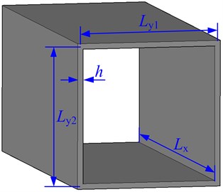
Table 1Comparison of natural frequencies obtained by MRRM and FEM for the box-type structure
Mode number | Natural frequencies and percentage errors | ||||||||
1 | 2 | 3 | 4 | 5 | 6 | 7 | 8 | ||
1 | FEM | 1.787 | 2.526 | 3.758 | 5.484 | 7.703 | 10.416 | 13.621 | 17.320 |
MRRM | 1.788087 | 2.528058 | 3.761279 | 5.487782 | 7.707571 | 10.420647 | 13.627011 | 17.326663 | |
P-Error | 0.06 % | 0.08 % | 0.09 % | 0.07 % | 0.06 % | 0.04 % | 0.04 % | 0.04 % | |
2 | FEM | 2.596 | 3.206 | 4.305 | 5.926 | 8.067 | 10.723 | 13.886 | 17.552 |
MRRM | 2.597011 | 3.207152 | 4.307759 | 5.928857 | 8.070860 | 10.726757 | 13.890259 | 17.556971 | |
P-Error | 0.04 % | 0.04 % | 0.06 % | 0.05 % | 0.05 % | 0.04 % | 0.03 % | 0.03 % | |
3 | FEM | 3.635 | 4.116 | 5.053 | 6.523 | 8.548 | 11.117 | 14.217 | 17.835 |
MRRM | 3.633189 | 4.116464 | 5.053479 | 6.524894 | 8.550082 | 11.119675 | 14.219630 | 17.838747 | |
P-Error | 0.05 % | 0.01 % | 0.01 % | 0.03 % | 0.02 % | 0.02 % | 0.02 % | 0.02 % | |
4 | FEM | 6.411 | 7.149 | 8.380 | 10.104 | 12.321 | 15.032 | 18.236 | 21.934 |
MRRM | 6.412601 | 7.152497 | 8.385686 | 10.112165 | 12.331930 | 15.044982 | 18.251319 | 21.950942 | |
P-Error | 0.02 % | 0.05 % | 0.07 % | 0.08 % | 0.09 % | 0.09 % | 0.08 % | 0.08 % | |
5 | FEM | 8.015 | 8.662 | 9.768 | 11.357 | 13.445 | 16.039 | 19.142 | 22.752 |
MRRM | 8.012426 | 8.664084 | 9.772218 | 11.363087 | 13.452738 | 16.048779 | 19.153304 | 22.765631 | |
P-Error | 0.03 % | 0.02 % | 0.04 % | 0.05 % | 0.06 % | 0.06 % | 0.06 % | 0.06 % | |
6 | FEM | 9.798 | 10.384 | 11.374 | 12.824 | 14.768 | 17.224 | 20.203 | 23.706 |
MRRM | 9.817337 | 10.387455 | 11.377389 | 12.827979 | 14.772323 | 17.230424 | 20.210830 | 23.714801 | |
P-Error | 0.20 % | 0.03 % | 0.03 % | 0.03 % | 0.03 % | 0.04 % | 0.04 % | 0.04 % | |
7 | FEM | 14.118 | 14.855 | 16.085 | 17.807 | 20.023 | 22.732 | 25.934 | 29.629 |
MRRM | 14.115270 | 14.858683 | 16.092494 | 17.819161 | 20.038987 | 22.752050 | 25.958374 | 29.657972 | |
P-Error | 0.02 % | 0.02 % | 0.05 % | 0.07 % | 0.08 % | 0.09 % | 0.09 % | 0.10 % | |
8 | FEM | 16.484 | 17.169 | 18.300 | 19.901 | 21.984 | 24.560 | 27.633 | 31.209 |
MRRM | 16.503369 | 17.175778 | 18.307301 | 19.910498 | 21.997010 | 24.575867 | 27.653055 | 31.231947 | |
P-Error | 0.12 % | 0.04 % | 0.04 % | 0.05 % | 0.06 % | 0.06 % | 0.07 % | 0.07 % | |
It can be found from Table 1 that, the natural frequencies obtained by MRRM and FEM agree well with each other. The maximum of the percentage errors is 0.20 %, and most of the percentage errors are no larger than 0.10 %. The small discrepancies in the results should be attributed to the approximation of FEM. Therefore, it indicates that MRRM is validate and of high precision for free vibration analysis of plate coupled structures such as the box-type structure.
3.2. The racetrack cylindrical shell
Consider an isotropic, racetrack cylindrical shell composed of thin plates and OCCSs with axial length 10 m, uniform thickness 0.01 m, circumferential length of the plate 4 m, middle surface radius of the OCCS 2 m, as shown in Fig. 5. The material properties of the racetrack cylindrical shell are the same as those defined for the box-type structure. The results for the natural frequencies of the racetrack cylindrical shell obtained by MRRM are compared with those obtained by FEM in Table 2, in which the notations are of the same meaning as those in Table 1.
Table 2 shows that the natural frequencies obtained by MRRM and FEM agree well with each other. The maximum of the percentage errors is 1.34%, and most of the percentage errors are no larger than 1.00 %. The difference between the results obtained by MRRM and FEM may be caused by the approximation of FEM and the different shell theories adopted by FEM and this paper. Therefore, it indicates that MRRM is validate for free vibration analysis of plate-shell coupled structures such as the racetrack cylindrical shell, and the results are of high precision.
Table 2Comparison of natural frequencies obtained by MRRM and FEM for the racetrack cylindrical shell
Mode number | Natural frequencies and percentage errors | ||||||||
1 | 2 | 3 | 4 | 5 | 6 | 7 | 8 | ||
1 | FEM | 2.151 | 2.953 | 4.090 | 5.715 | 7.854 | 10.508 | 13.670 | 17.336 |
MRRM | 2.151035 | 2.957795 | 4.099758 | 5.727604 | 7.869848 | 10.525766 | 13.689947 | 17.357884 | |
P-Error | 0.00 % | 0.16 % | 0.24 % | 0.22 % | 0.20 % | 0.17 % | 0.15 % | 0.13 % | |
2 | FEM | 5.383 | 6.984 | 8.461 | 10.232 | 12.415 | 15.064 | 18.200 | 21.832 |
MRRM | 5.456198 | 7.031901 | 8.506268 | 10.281368 | 12.471784 | 15.128039 | 18.271764 | 21.911835 | |
P-Error | 1.34 % | 0.68 % | 0.53 % | 0.48 % | 0.46 % | 0.42 % | 0.39 % | 0.36 % | |
3 | FEM | 5.444 | 13.162 | 15.027 | 17.038 | 19.382 | 22.133 | 25.328 | 28.989 |
MRRM | 5.514263 | 13.195591 | 15.093706 | 17.133938 | 19.500229 | 22.270141 | 25.483314 | 29.162474 | |
P-Error | 1.27 % | 0.25 % | 0.44 % | 0.56 % | 0.61 % | 0.62 % | 0.61 % | 0.59 % | |
4 | FEM | 10.458 | 20.291 | 23.281 | 25.846 | 28.524 | 31.492 | 34.835 | 38.598 |
MRRM | 10.460565 | 20.468996 | 23.452468 | 26.038717 | 28.741440 | 31.738403 | 35.110916 | 38.903664 | |
P-Error | 0.02 % | 0.87 % | 0.73 % | 0.74 % | 0.76 % | 0.78 % | 0.79 % | 0.79 % | |
5 | FEM | 10.684 | 20.334 | 33.382 | 36.659 | 39.751 | 43.017 | 46.583 | 50.513 |
MRRM | 10.687016 | 20.525417 | 33.560942 | 36.926488 | 40.084378 | 43.403142 | 47.016813 | 50.994129 | |
P-Error | 0.03 % | 0.93 % | 0.53 % | 0.72 % | 0.83 % | 0.89 % | 0.92 % | 0.94 % | |
6 | FEM | 13.803 | 27.932 | 33.447 | 48.481 | 52.618 | 56.447 | 60.381 | 64.577 |
MRRM | 13.927559 | 27.962842 | 33.633721 | 48.880722 | 53.107713 | 57.012575 | 61.015628 | 65.278488 | |
P-Error | 0.89 % | 0.11 % | 0.56 % | 0.82 % | 0.92 % | 0.99 % | 1.04 % | 1.07 % | |
7 | FEM | 15.378 | 28.755 | 42.048 | 48.529 | 66.309 | 71.352 | 75.927 | 80.554 |
MRRM | 15.492372 | 28.837613 | 42.200925 | 48.948598 | 66.815182 | 72.081826 | 76.777865 | 81.507231 | |
P-Error | 0.74 % | 0.29 % | 0.36 % | 0.86 % | 0.76 % | 1.01 % | 1.11 % | 1.17 % | |
8 | FEM | 15.955 | 30.057 | 42.961 | 57.665 | 72.451 | 84.556 | 92.219 | 97.881 |
MRRM | 15.956436 | 30.175983 | 43.324195 | 57.735824 | 72.588720 | 84.589523 | 93.167426 | 99.063747 | |
P-Error | 0.01 % | 0.39 % | 0.84 % | 0.12 % | 0.19 % | 0.04 % | 1.02 % | 1.19 % | |
Fig. 5Geometry and notations of a racetrack cylindrical shell
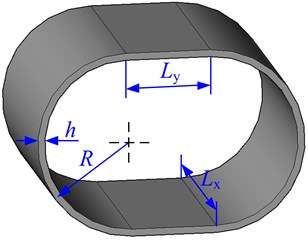
Fig. 6Geometry and notations of a ship hull structure
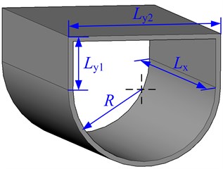
3.3. The ship hull structure
In this subsection, the natural frequencies of the ship hull structure, as shown in Fig. 6, with two opposite edges simply supported are calculated. The material properties of the ship hull structure are the same as those defined for the box-type structure. The geometrical parameters are: 10 m, 2 m, 4m, 2 m and 0.01 m. The results for the natural frequencies of the box-type structure obtained by MRRM are compared with those obtained by FEM in Table 3, where the notations are of the same meaning as those in Tables 1 and 2.
Table 3Comparison of natural frequencies obtained by MRRM and FEM for the ship hull structure
Mode number | Natural frequencies and percentage errors | ||||||||
1 | 2 | 3 | 4 | 5 | 6 | 7 | 8 | ||
1 | FEM | 2.562 | 5.713 | 6.575 | 8.847 | 13.875 | 16.349 | 16.377 | 20.440 |
MRRM | 2.574674 | 5.803015 | 6.651149 | 8.818441 | 13.925635 | 16.342406 | 17.035003 | 20.525130 | |
P-Error | 0.49 % | 1.55 % | 1.14 % | 0.32 % | 0.36 % | 0.04 % | 3.86 % | 0.41 % | |
2 | FEM | 3.217 | 7.027 | 8.241 | 9.973 | 16.702 | 21.496 | 22.775 | 28.663 |
MRRM | 3.222129 | 7.072771 | 8.300801 | 9.991594 | 16.703286 | 21.734920 | 23.026966 | 27.617563 | |
P-Error | 0.16 % | 0.65 % | 0.72 % | 0.19 % | 0.01 % | 1.10 % | 1.09 % | 3.79 % | |
3 | FEM | 4.318 | 8.407 | 9.681 | 11.209 | 18.061 | 24.346 | 25.892 | 30.900 |
MRRM | 4.322056 | 8.441562 | 9.737088 | 11.237360 | 18.073568 | 24.512647 | 26.124280 | 31.037877 | |
P-Error | 0.09 % | 0.41 % | 0.58 % | 0.25 % | 0.07 % | 0.68 % | 0.89 % | 0.44 % | |
4 | FEM | 5.934 | 10.159 | 11.372 | 12.757 | 19.754 | 26.778 | 28.435 | 32.886 |
MRRM | 5.937682 | 10.193966 | 11.432079 | 12.791735 | 19.773413 | 26.937417 | 28.661965 | 33.011183 | |
P-Error | 0.06 % | 0.34 % | 0.53 % | 0.27 % | 0.10 % | 0.59 % | 0.79 % | 0.38 % | |
5 | FEM | 8.071 | 12.362 | 13.460 | 14.723 | 21.882 | 29.349 | 31.044 | 35.145 |
MRRM | 8.075624 | 12.400127 | 13.527708 | 14.764371 | 21.906555 | 29.520271 | 31.286598 | 35.270387 | |
P-Error | 0.06 % | 0.31 % | 0.50 % | 0.28 % | 0.11 % | 0.58 % | 0.78 % | 0.36 % | |
6 | FEM | 10.725 | 15.043 | 16.010 | 17.168 | 24.480 | 32.245 | 33.918 | 37.775 |
MRRM | 10.729149 | 15.085841 | 16.086390 | 17.215377 | 24.509296 | 32.435677 | 34.185502 | 37.908113 | |
P-Error | 0.04 % | 0.28 % | 0.47 % | 0.28 % | 0.12 % | 0.59 % | 0.78 % | 0.35 % | |
7 | FEM | 13.886 | 18.212 | 19.052 | 20.122 | 27.566 | 35.541 | 37.152 | 40.826 |
MRRM | 13.891362 | 18.261305 | 19.137747 | 20.174461 | 27.599471 | 35.755749 | 37.449705 | 40.969879 | |
P-Error | 0.04 % | 0.27 % | 0.45 % | 0.26 % | 0.12 % | 0.60 % | 0.79 % | 0.35 % | |
8 | FEM | 17.552 | 21.874 | 22.599 | 23.598 | 31.149 | 39.276 | 40.800 | 44.330 |
MRRM | 17.557387 | 21.930540 | 22.694437 | 23.653557 | 31.186065 | 39.516188 | 41.130030 | 44.484581 | |
P-Error | 0.03 % | 0.26 % | 0.42 % | 0.23 % | 0.12 % | 0.61 % | 0.80 % | 0.35 % | |
It can be observed from Table 3 that, the natural frequencies obtained by MRRM and FEM agree well with each other. Except for certain mode numbers, the maximum of the percentage errors is 1.55 %, and most of the percentage errors are no larger than 1.00 %. The difference between the results obtained by MRRM and FEM may be caused by the approximation of FEM and the different shell theories adopted by FEM and this paper. Therefore, it indicates that MRRM is applicable for free vibration analysis of plate-shell coupled structures such as the ship hull structure, and the results are of high precision.
4. Conclusions
This paper presents a semi-analytical solution procedure and accurate calculation results for plate/shell coupled structures with two opposite edges simply supported. The validity and applicability of the MRRM for free vibration analysis of plate/shell coupled structures are verified. It has been proved that the results obtained by MRRM are in excellent agreement with those obtained by FEM and that high precision of MRRM has been shown. MRRM is advantageous in its simple and uniform formulation as well as accurate results for dynamic response analysis of coupled structures.
It should be pointed out that the method of reverberation-ray matrix only applies to plate/shell coupled structures with two opposite edges simply-supported at present. This limitation may be breached by replacing the standing wave form solution with the combination of the trigonometric function and the tangent or cotangent functions. The effects of the structural parameters, boundary conditions and connection forms on the vibration characteristics of the plate/shell coupled structures will be discussed in the subsequent researches.
References
-
Irie T., Yamada G., Kobayash Y. Free vibration of a cantilever folded plate. The Journal of the Acoustical Society of America, Vol. 76, Issue 6, 1984, p. 1743-1748.
-
Eterovic A. L., Godoy L. A. An exact strip method for folded plate structures. Computers and Structures, Vol. 32, Issue 2, 1989, p. 263-276.
-
Maleki S. Compound strip method for box girders and folded plates. Computers and Structures, Vol. 40, Issue 3, 1991, p. 527-538.
-
Liu W. H., Huang C. C. Vibration analysis of folded plates. Journal of Sound and Vibration, Vol. 157, Issue 1, 1992, p. 123-137.
-
Hinton E., Özakça M., Rao N. V. R. Free vibration analysis and shape optimization of variable thickness plates, prismatic folded plates and curved shells. Part 1: finite strip formulation. Journal of Sound and Vibration, Vol. 181, Issue 4, 1995, p. 553-566.
-
Niyogi A. G., Laha M. K., Sinha P. K. Finite element vibration analysis of laminated composite folded plate structures. Shock and Vibration, Vol. 6, Issues 5-6, 1999, p. 273-283.
-
Samanta A., Mukhopadhyay M. Finite element static and dynamic analyses of folded plates. Engineering Structures, Vol. 21, Issue 3, 1999, p. 277-287.
-
Lai Y., Yu W. Analytical solution for forced vibration of a simply-supported V-shaped folded plate roof. Thin-Walled Structures, Vol. 40, Issue 3, 2002, p. 215-223.
-
Peng L. X., Kitipornchai S., Liew K. M. Free Vibration Analysis of Folded Plate Structures by the FSDT Mesh-free Method. Computational Mechanics, Vol. 39, Issue 6, 2007, p. 799-814.
-
Cuschieri J. M. Structural power-flow analysis using a mobility approach of an L-shaped plate. The Journal of the Acoustical Society of America, Vol. 87, Issue 3, 1990, p. 1159-1165.
-
Cuschieri J. M. Parametric analysis of the power flow on an L-shaped plate using a mobility power flow approach. The Journal of the Acoustical Society of America, Vol. 91, Issue 5, 1992, p. 2686-2695.
-
Wang Z. H., Xing J. T., Price W. G. An investigation of power flow characteristics of L-shaped plates adopting a substructure approach. Journal of Sound and Vibration, Vol. 250, Issue 4, 2002, p. 627-648.
-
Kessissoglou N. J. Power transmission in L-shaped plates including flexural and in-plane vibration. The Journal of the Acoustical Society of America, Vol. 115, Issue 3, 2004, p. 1157-1169.
-
Chen X., Sheng M. Research on vibration characteristics of L-shaped plate using a mobility power flow approach. Journal of Marine Science and Application, Vol. 6, Issue 3, 2007, p. 12-16.
-
Liu C., Li F., Huang W. Active vibration control of finite L-shaped beam with travelling wave approach. Acta Mechanica Solida Sinica, Vol. 23, Issue 5, 2010, p. 377-385.
-
Lin T. R., Tan C. C., Yan C., Hargreaves D. Vibration of L-shaped plates under a deterministic force or moment excitation: a case of statistical energy analysis application. Journal of Sound and Vibration, Vol. 330, Issue 20, 2011, p. 4780-4797.
-
Liu C., Li F., Tang L., Huang W. Vibration control of the finite L-shaped beam structures based on the active and reactive power flow. Science China Physics, Mechanics and Astronomy, Vol. 54, Issue 2, 2011, p. 310-319.
-
Liu C., Li F., Liang T., Huang W. Early short time transient response of finite L-shaped Mindlin plate. Wave Motion, Vol. 48, Issue 5, 2011, p. 371-391.
-
Liu C., Li F., Liang T., Huang W. The wave and vibratory power transmission in a finite L-shaped Mindlin plate with two simply supported opposite edges. Acta Mechanica Sinica, Vol. 27, Issue 5, 2011, p. 785-795.
-
Lin Y., Wu W., Li X., Gan J. Study on transmission law of flexural waves through L-shaped steel-aluminum joints. The Twenty-second International Offshore and Polar Engineering Conference, International Society of Offshore and Polar Engineers, 2012.
-
Dickinson S., Warburton G. Vibration of box-type structures. Journal of Mechanical Engineering Science, Vol. 9, Issue 4, 1967, p. 325-338.
-
Popplewell N. The vibration of a box-type structure I. Natural frequencies and normal modes. Journal of Sound and Vibration, Vol. 14, Issue 3, 1971, p. 357-365.
-
Handa K. Analysis of in-plane vibration of box-type structures by a finite element method. Journal of Sound and Vibration, Vol. 21, Issue 1, 1972, p. 107-114.
-
Fulford R. A., Petersson B. A. T. Estimation of vibrational power in built-up systems involving box-like structures. Part 1: uniform force distribution. Journal of Sound and Vibration, Vol. 232, Issue 5, 2000, p. 877-895.
-
Fulford R. A., Petersson B. A. T. Estimation of vibrational power in built-up systems involving box-like structures. Part 2: infinite top-plate and circular geometry. Journal of Sound and Vibration, Vol. 232, Issue 5, 2000, p. 897-915.
-
Lee S. Y., Wooh S. C. Finite element vibration analysis of composite box structures using the high order plate theory. Journal of Sound and Vibration, Vol. 277, Issues 4-5, 2004, p. 801-814.
-
Lin T. R., Pan J. Vibration characteristics of a box-type structure. Journal of Vibration and Acoustics, Vol. 131, Issue 3, 2009, p. 1-9.
-
Lin T. R., Pan J. Sound radiation characteristics of a box-type structure. Journal of Sound and Vibration, Vol. 325, Issues 4-5, 2009, p. 835-851.
-
Chen Y., Jin G., Zhu M., Liu Z., Du J., Li W. Vibration behaviors of a box-type structure built up by plates and energy transmission through the structure. Journal of Sound and Vibration, Vol. 331, Issue 4, 2012, p. 849-867.
-
Yamada G., Irie T., Tamiya T. Free vibration of a circular cylindrical double-shell system closed by end plates. Journal of Sound and Vibration, Vol. 108, Issue 2, 1986, p. 297-304.
-
Schlesinger A. Transmission of elastic waves from a cylinder to an attached flat plate. Journal of Sound and Vibration, Vol. 186, Issue 5, 1995, p. 761-780.
-
Tso Y. K., Hansen C. H. Wave propagation through cylinder/plate junctions. Journal of Sound and Vibration, Vol. 186, Issue 3, 1995, p. 447-461.
-
Stanley A. J., Ganesan N. Frequency response of shell-plate combinations. Computers and Structures, Vol. 59, Issue 6, 1996, p. 1083-1094.
-
Tso Y. K., Hansen C. H. An investigation of the coupling loss factor for a cylinder/plate structure. Journal of Sound and Vibration, Vol. 199, Issue 4, 1997, p. 629-643.
-
Wu J. H., Chen H. L., An W. B. A method to predict sound radiation from a plate-ended cylindrical shell excited by an external force. Journal of Sound and Vibration, Vol. 237, Issue 5, 2000, p. 739-803.
-
Wang Z. H., Xing J. T., Price W. G. A study of power flow in a coupled plate-cylindrical shell system. Journal of Sound and Vibration, Vol. 271, Issues 3-5, 2004, p. 863-882.
-
Liang S., Chen H. L. The natural vibration of a conical shell with an annular end plate. Journal of Sound and Vibration, Vol. 294, Issue 4-5, 2006, p.927-943.
-
Liang S., Chen H. L., Chen T., Wang M. Y. The natural vibration of a symmetric cross-ply laminated composite conical-plate shell. Composite Structures, Vol. 80, Issue 2, 2007, p. 265-278.
-
Efraim E., Eisenberger M. Exact vibration frequencies of segmented axisymmetric shells. Thin-Walled Structures, Vol. 44, Issue 3, 2006, p. 281-289.
-
Caresta M., Kessissoglou N. J. Free vibrational characteristics of isotropic coupled cylindrical-conical shells. Journal of Sound and Vibration, Vol. 329, Issue 6, 2010, p. 733-751.
-
Kang J. H. Three-dimensional vibration analysis of joined thick conical-Cylindrical shells of revolution with variable thickness. Journal of Sound and Vibration, Vol. 331, Issue 18, 2012, p. 4187-4198.
-
Qu Y., Chen Y., Long X., Hua H., Meng G. A modified variational approach for vibration analysis of ring-stiffened conical-cylindrical shell combinations. European Journal of Mechanics – A/Solids, Vol. 37, 2013, p. 200-215.
-
Qu Y., Wu S., Chen Y., Hua H. Vibration analysis of ring-stiffened conical-cylindrical-spherical shells based on a modified variational approach. International Journal of Mechanical Sciences, Vol. 69, 2013, p. 72-84.
-
Shakouri M., Kouchakzadeh M. A. Stability analysis of joined isotropic conical shells under axial compression. Thin-Walled Structures, Vol. 72, 2013, p. 20-27.
-
Wu S., Qu Y., Hua H. Vibration characteristics of a spherical-cylindrical-spherical shell by a domain decomposition method. Mechanics Research Communications, Vol. 49, 2013, p. 17-26.
-
Kouchakzadeh M. A., Shakouri M. Free vibration analysis of joined cross-ply laminated conical shells. International Journal of Mechanical Sciences, Vol. 78, 2014, p. 118-125.
-
Ma X., Jin G., Xiong Y., Liu Z. Free and forced vibration analysis of coupled conical-cylindrical shells with arbitrary boundary conditions. International Journal of Mechanical Sciences, Vol. 88, 2014, p. 122-137.
-
Shakouri M., Kouchakzadeh M. A. Free vibration analysis of joined conical shells: analytical and experimental study. Thin-Walled Structures, Vol. 85, 2014, p. 350-358.
-
Su Z., Jin G., Ye T. Three-dimensional vibration analysis of thick functionally graded conical, cylindrical shell and annular plate structures with arbitrary elastic restraints. Composite Structures, Vol. 118, 2014, p. 432-447.
-
Xie X., Zheng H., Jin G. Integrated orthogonal polynomials based spectral collocation method for vibration analysis of coupled laminated shell structures. International Journal of Mechanical Sciences, Vol. 98, 2015, p. 132-143.
-
Tang D., Pang F., Wang Q., Yao X. Research on transmission loss of power flow through a finite V-shaped plate. Journal of Vibration Engineering, Vol. 29, Issue 1, 2016, p. 112-122.
-
Tang D., Wu G., Yao X., Wang C. Free vibration analysis of circular cylindrical shells with arbitrary boundary conditions by the method of reverberation-ray matrix. Shock and Vibration, 2016.
-
Yao X., Tang D., Pang F., Li S. Exact free vibration analysis of open circular cylindrical shells by the method of reverberation ray matrix. Journal of Zhejiang University – Science A (Applied Physics and Engineering), Vol. 17, Issue 4, 2016, p. 295-316.
-
Tang D., Sun L., Yao X., Yue X. Free vibration analysis of open circular cylindrical shells by the method of reverberation-ray matrix. Advances in Mechanical Engineering, Vol. 8, Issue 3, 2016, p. 1-21.
About this article

This work is financially supported by National Natural Science Foundation of China (Grant Nos. 51479041, 51279038). The authors would like to express their profound thanks for the financial support and sincerely thank Miss Jingjing Yu for the scientific discussions and suggestions and the anonymous reviewers for the critical and constructive comments on this paper.
