Abstract
This paper adopts a modified Fourier-Ritz approach to study the free vibration characteristics of orthotropic circular, annular and sector thin plates subjected to general boundary conditions. For the arbitrary plate forms and the boundary conditions, the displacements can be written in the form of a standard Fourier cosine series supplemented with several auxiliary functions. The auxiliary functions, which are closed-form and introduced to remove all the potential discontinuities of the original displacement function and its derivatives in the whole domain, can be usefully employed in improving the convergence of the results. The artificial boundary spring technique and artificial coupling spring technique are adopted to simulate the arbitrary boundary conditions and to ensure appropriate continuity conditions along the radial edges, respectively. Because the displacement field is sufficiently smooth in the whole solution domain, the accurate solution can be obtained by using the Ritz procedure on the basis of the energy functions. The accuracy, reliability and versatility of the current method are fully demonstrated and verified through numerical examples involving plates with various shapes and boundary conditions.
1. Introduction
Orthotropic circular, annular and sector thin plates have achieved a wide range of applications, such as ships, aeronautical and space structures and other industrial applications, since they own excellent engineering features. In view of this, it’s of great necessary to master the understanding of the vibration characteristics for the orthotropic circular, annular and sector plates, which contributes to the accurate and efficient structure design.
In the past few decades, a large quantity of techniques has been developed to solve vibration problems of the circular, annular and sector thin plates. The contour vibrations of isotropic circular plates were investigated by Onoe [1] using a mathematical method on the basis of Love’s theory. Wang and Thevendran [2] solved the free vibration problem of annular plates with internal axisymmetric supports employing the Rayleigh-Ritz method. Wang et al. [3] performed free vibration analysis of annular plates with classical boundary conditions by the differential quadrature method. Mcgee et al. [4] analyzed free vibration of sectorial plates with complete free boundary conditions by a novel Ritz method. Then, the differential quadrature method was developed by Wang et al. [5] to study the free vibration of circular annular plates with classical boundary conditions and non-uniform thickness. Moreover, Wang [6] also extended the differential quadrature method to research the free vibration of thin sector plates with various sector angles and six combinations of classical boundary conditions. The free vibration of ring-shaped polar-orthotropic sector plates with classical boundary conditions was investigated by Irie et al. [7] using the Ritz method. Singh et.al [8] analyzed the transverse vibrations of a circular plates with variable thickness and classical boundary conditions adopting the Rayleigh-Ritz method. Extending the mode subtraction method, Wong et al. [9, 10] studied the sensitivity of changes in displacement mode shape of annular plates relative to the hole size and obtained approximations to frequencies and mode shapes of circular plates with variable thicknesses. Houmat [11] developed a sector Fourier -element on the basis of finite element method to conduct free vibration analysis of sectorial plates with classical boundary conditions. The free vibration analysis of circular and rectangular clamped plates with the clamped boundary condition was studied by Chen et.al [12] using the meshless method. Seok and Tiersten [13, 14] presented a variational approximation procedure for free vibrations analysis of annular sector cantilever plates. Aghdam et al. [15] performed bending analysis of thin annular sector plates with clamped boundary condition by extended Kantorovich method. The free vibration of circular and annular sectorial thin plates with classical boundary conditions was investigated by Li [16] using the finite strip method. Kim and Yoo [17] used a novel analytical solution to investigate flexural responses of annular sector thin plates with classical boundary conditions. Mirtalaie and Hajabasi [18] took the differential quadrature method to study the free vibration of annular sector thin plates with classical boundary conditions. Shi et.al [19] presented an improved Fourier series method to solve the free vibration of isotropic circular, annular and sector thin plates with arbitrary boundary conditions.
Through the above review, it reveals that the existing free vibration investigations mostly center on the isotropic circular, annular and sector thin plates, while the study focusing on the orthotropic circular, annular and sector thin plate is not nearly enough. And most of them primarily are devoted to the plates with particular shapes and under a specific type of boundary conditions. In addition, the existing solution procedures developed to solve the vibration problem of the circular, annular and sector thin plates are often just customized for a specific set of different boundary conditions by setting special trial functions. However, it’s well known to us that the structure elements would stand a variety of boundary conditions including classical case, elastic case and their combination in the practice engineering applications. Thus, applying the existing solution procedures to support designers in the pre-design of the engineering applications will result in very tedious and inefficient work. As far as the authors know, there has been no reported solutions for a unified vibration analysis of orthotropic annular, circular and sector plates with arbitrary boundary conditions in the literature. So, it’s urgent and of important significance to present a unified, efficient and accurate enough formulation to handle the free vibration problem of orthotropic annular, circular and sector plates subjected to general boundary conditions.
Recently, Li [20, 21] proposed an improved Fourier series technique to solve the vibration analysis of the beams and plates with general boundary conditions. Later, Jin and Shi et al. extended the method to study the free vibration of the plates and shells [22-30]. In this technique, the displacement of a considered structure is expressed as a conventional cosine Fourier series with the addition of several supplementary terms. Taking linear vibration of a classical beam for example, the target of introducing these supplementary terms is introduced, which contributes to a better understanding: For a special set of boundary conditions, the exact solution always exists by means of setting trial functions of a classical beam. For instance, an exact solution exists in the form of sine Fourier series when the beam is under simply-supported ends. But when the boundary condition changes, the sine Fourier series is not applicable to other boundary conditions any longer. Because the displacements of the beam are periodically extended as standard Fourier series onto the beam domain, discontinuities potentially exist in original displacements and their derivatives at the ends. In this case, the expanded expressions cannot be differentiated term-by-term, and thus the solution may not converge or converge slowly because of its potential convergence problem.
This paper aims to present a method to unify the solutions for plates with different shapes, i.e. circular plate, annular plate, circular sector plate and annular sector plate, subjected to general boundary conditions. Under the framework of this paper, the plate displacements are always constructed as a combination of a standard Fourier cosine series and several auxiliary closed-form functions, no matter what the shapes of the plates and the types of the boundary conditions are. These auxiliary functions, which are used to remove any potential discontinuities occurred in the original displacement function and its derivatives throughout the whole domain including its edges, can greatly improve the convergence of the results. The excellent accuracy and reliability of the current solutions are validated by comparing with the results obtained from the ABAQUS solution, and numerous new results for orthotropic circular, annular and sector thin plates with various boundary conditions are presented.
2. Theoretical formulations
2.1. Description of the model
The orthotropic annular sector plate studied in this paper is given in Fig. 1. It is with a uniform thickness of , and the inner radius , outer radius , width () in the radial direction and the sector angle are also marked in Fig. 1. An orthogonal cylindrical coordinate system is adopted to describe the geometry and dimensions of the model. Since this paper is to present a unified solution to conduct free vibration analysis of the orthotropic plates with different shapes (namely, the orthotropic circular, annular and sector plates) subjected to general boundary conditions, so how to obtain the other two plates on the basis of the annular sector plate is explained here. As shown in Fig. 2, for case of the circular sector plate, we only need to set the inner radial equal to zero; for case of the annular plate, two conditions are required: (a) the sector angle of the annular sector plate is equal to 2; (b) on the basis of the conditions (a), the kinematic and physical compatibility conditions should be satisfied at the coupling radial edges of 0 and . Thus, to achieve the goal, it is necessary to adopt the coupling springs to implement the kinematic and physical compatibility conditions between the two computational meridians of 0 and . Lastly, the formulation of the circular plate can be easily obtained by setting the inner radial equal to zero based on the assumptions of the annular plate.
Fig. 1An orthotropic annular sector plate with arbitrary out-plane elastic edge supports
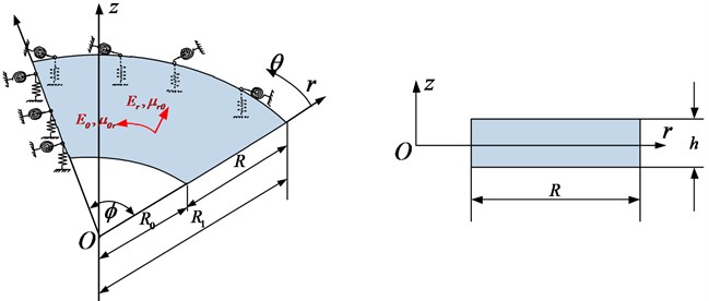
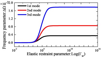
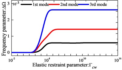
Fig. 2Variation of the frequency parameters Ω versus the elastic boundary restraint parameters for annular sector plate
2.2. Energy expressions
For small deformations, the strain-displacement relations in local cylindrical coordinate system can be expressed as:
According to the Hooke’s law, the corresponding stress-strain relations of the orthotropic thin circular, annular and sector plates can be written as:
where and are the Young’s moduli, and are the Poisson’s ratios in the radial and circumferential directions, respectively, among which there is a well-known relation of . is the shear modulus.
The strain energy of the sector plate is given as:
Submitting Eqs. (1) and (2) into Eq. (3) will lead to the following expression for the strain energy:
where is the sector plate deflection, are the standard bending rigidities in the classical lamination theory:
By neglecting the rotary inertia, the kinetic energy of an orthotropic annular sector thin plate can be written as:
As mentioned earlier, to develop a unified solution to handle with the free vibration problems of orthotropic circular, annular and sector plates with general boundary conditions, the artificial spring boundary technique should be introduced. In this technique, both one group of linear springs and one group of rotational springs are arranged at every boundary of the plate to simulate the boundary forces. With the aid of this technique, the given boundary conditions can be readily achieved just by changing the stiffness values of these springs. For example, if the spring stiffness is set substantially larger than the bending rigidity of the plate, the clamped boundary condition is simulated. The deformation strain energy () stored in the boundary springs during vibration can be defined as:
As mentioned earlier, we need one group of linear coupling springs () and one group of rotation coupling springs () to simulate the annular plates and circular plate when the inclusion or sector angle is equal to 2. Therefore, the potential energies () stored in in the two types of coupling springs can be defined as:
For three special cases, i.e. the annular sector plate degenerates to a circular sector plate or annular plates and the circular sector plate degenerates to a circular plate, the stiffnesses of corresponding springs used at the inner edge or coupling boundary of the annular sector plate and inner edge together with the coupling boundary are revalued to be zero automatically.
On the basis of the above energy expressions, the Lagrangian functional () of the plates yields:
The governing equations of the orthotropic circular, annular and sector plates can be obtained by applying the Hamilton’s principle. Thus, the governing equations of the orthotropic plates are obtained as:
2.3. Admissible displacement functions and solution procedure
Looking for the appropriate admissible displacement function is quite vital in the present method. It is expected that the displacement functions are expressed in the form of a Fourier series expansion because Fourier functions constitute a complete set and exhibit good numerical stability. However, the conventional Fourier series expression is generally only effective for a few simple classical boundary conditions, and when applied to other complex boundary conditions, it usually generates the convergence problem along the boundary. Mathematically, when the displacement of the plate is expanded as standard Fourier series onto the entire solution domain, discontinuities may potentially exist in original displacements and their derivatives at the edges. In addition, if not uniformly convergent, these derivatives cannot be easily acquired through term-by-term differentiation any longer.
Such problems can be overcome by a more robust form of Fourier series expansion, and the displacement function in this form is as follows:
where is angular frequency, denotes time, , , is the Fourier coefficients of two-dimensional Fourier series expansions for the displacements functions. and are the supplemented coefficients of the auxiliary functions. They all need determining further. Through the governing equations, it can be known that, to guarantee that the plate displacement functions and their corresponding derivatives at any point are continuous, the three-order derivative of the displacement function should exist. And as for the admissible function, at least its fourth-order derivatives need exist and be continuous at all points of the structure. In this paper, the following functions are chosen as the auxiliary terms which can efficiently meet the above continuous requirements:
It’s not hard to prove that the first and third derivatives along the boundary of these functions mostly equal to zeros in addition to the following cases:
It can be proven mathematically that the series expression in Eq. (11) is able to expand and uniformly converge to any function for . Its series expansions for up to the fourth-order derivative, which are also uniformly convergent, can be easily derived through term-by-term differentiation. Mathematically, an exact displacement (or classical) solution is a particular function for and it needs to follow both the governing equation at every field point and the boundary conditions at every boundary point.
After establishing the admissible displacement functions of the sector plate, next we should find a suitable set of expansion coefficients that will ensure the series, as a whole, satisfies both the governing equations and the boundary conditions in some way. A solution can be obtained either in the strong form by letting the series satisfy the relevant equations exactly on a point-wise basis, or in the weak form by solving the series coefficients approximately using, for instance, the Rayleigh-Ritz technique. The weak form of solution will be sought here since it will be more attractive in modeling complex structures. Thus, substituting Eqs. (4-8) and Eq. (11) into Eq. (9) and performing the Rayleigh–Ritz procedure with regard to each unknown coefficient, the motion equation of plates yields and for conciseness, it’s written in matrix form:
where:
In Eq. (18), and are the stiffness matrix and mass matrix of the plate, respectively. The natural frequencies and eigenvectors can be easily determined by solving a standard matrix eigenvalue problem. Each of the eigenvectors actually contains the series expansion coefficients for the corresponding mode. The physical mode shapes can be simply obtained by using Eq. (11).
3. Numerical results and discussion
In this section, the free vibration of the orthotropic circular, annular and sector thin plate is investigated based on the theoretical formulations developed in the previous section, and several numerical results are calculated. If there are no other special notes, the non-dimensional is always used in this paper, and the material properties of orthotropic plates keep the following settings: 7850 kg/m3, 70 GPa, , 3.51 GPa, 0.3.
3.1. Spring and convergence study
In the theoretical formulation, the artificial spring boundary technique is introduced to simulate the given boundary conditions. Furthermore, we need one group of liner couplings spring and one group of rotation coupling springs along the coupling boundary to enforce the continuity conditions for the displacements at the edges 0 and . In real calculation, the case of classical boundary conditions can be easily simulated by assigning proper stiffness values to the boundary springs, for instance, the simply-supports boundary (S) can be readily achieved by simply setting the stiffness of the linear spring to be infinitely large and the rotation spring to be zeros; the case of coupling springs of orthotropic annular sector plates (sector angle is equal to 2) and circular sector plate (sector angle is equal to 2) can be easily generated by assigning proper stiffness to be “infinitely large” to imitate the orthotropic annular plates and circular plate. In fact, the “infinitely large” is unrealistic and meaningless in actual calculations, and we only choose a sufficiently large number. So it can be seen that the boundary spring stiffness and the coupling spring stiffness have a significant effect on the modal characteristics and we should make it clear firstly.
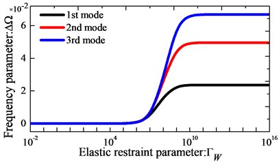
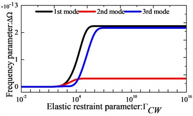
As the first example, we focus on the effect of the elastic boundary restraint parameters on the frequency parameter of orthotropic circular, annular and sector plate. In Fig. 2, the variations of the lowest three frequency parameters versus the elastic restraint parameters for orthotropic thin annular sector plates are presented. Here, the frequency parameter is . The boundary condition is clamped at boundaries and elastically supported by only one group of spring components with stiffness varying from 10-2 to 1016 at boundaries , and the rest of the boundary conditions are free. The geometric dimensions of the plates used in analysis are given as: 90o, 1 m, 2 and 0.001. From Fig. 2, it is observed that the frequency parameters increase as the stiffness parameters increase in the certain range. It is shown that the active ranges of stiffness parameters vary with the change of boundary springs. Next, effects of elastic coupling restraint stiffness parameters on the frequency parameters of orthotropic annular and circular plates are also studied. The variations of the lowest three frequency parameters versus the elastic coupling restraint parameters are given in Fig. 3. It is seen from Fig. 3 that both translational and rotational coupling restraints can meaningfully affect the natural frequencies of the plate. And it also reveals that when the non-dimensional stiffness of the liner coupling springs and is larger than 106 or smaller than 101, their effect on the frequency parameters will almost remain unchanged.
Fig. 3Variation of the frequency parameters Ω versus the elastic coupling restraint parameters
Based on the analysis, it can be found the frequency parameters exist the large change as the stiffness parameters increase in the certain range. The “infinitely large” stiffness of the boundary springs and coupling springs can be realized by assigning the boundary spring stiffness to 1014 and 1012, respectively. In the following discussions, transverse vibration frequencies and modal shapes of orthotropic circular, annular and sector plates with arbitrary classical boundary conditions, general elastic boundary conditions and their combinations will be presented. In the following, the spring stiffness parameters corresponds to six kinds of commonly encountered boundary conditions are listed, taking the edge as an example:
The selection of appropriate admissible functions is of critical importance in the Rayleigh-Ritz method because the accuracy and efficiency of solutions depend greatly on the selected displacement functions. In the actual calculations, the proposed modified Fourier series expressions are truncated to and to obtain the results with acceptable accuracy due to the limited speed, the capacity and the numerical accuracy of computers. Therefore, it is of great importance to check its accuracy, convergence and numerical robustness. The first eight frequency parameters for orthotropic annular sector plates, circular sector plate, annular plate and circular plate subjected to clamped boundary conditions and different truncated number and (i.e. 10, 11, 12, 13, 14) are given in Table 1. The geometric dimensions of the plates used in analysis are given as: for the annular sector plate: 90°, 1 m, 2 and 0.001, for the annular plate: 360°, 1 m, 2 and 0.001, for the circular sector plate: 90°, 1 m and 0.001, for the circular plate: 360°, 1 m and 0.001. From Table 1, it can be seen that the natural frequencies converge monotonically and rapidly as the truncation number and increase. The modified Fourier-Ritz approach has an excellent convergence. According to the convergence of results in Table 1, the truncated numbers will be selected as 12 in the rest of studies. For further validation of the current solution, more numerical examples will be presented.
Table 1Convergence of the first eight frequency parameters Ω for circular, annular and sector plates with complete clamped boundary conditions
Plate form | Mode number | ||||||||
1 | 2 | 3 | 4 | 5 | 6 | 7 | 8 | ||
Annular sector plate | 10 | 0.1624 | 0.1636 | 0.1665 | 0.1734 | 0.1800 | 0.1936 | 0.2124 | 0.2368 |
11 | 0.1624 | 0.1636 | 0.1665 | 0.1717 | 0.1806 | 0.1933 | 0.2119 | 0.2347 | |
12 | 0.1624 | 0.1636 | 0.1664 | 0.1716 | 0.1805 | 0.1933 | 0.2117 | 0.2344 | |
13 | 0.1624 | 0.1636 | 0.1664 | 0.1715 | 0.1804 | 0.1932 | 0.2115 | 0.2344 | |
14 | 0.1624 | 0.1636 | 0.1664 | 0.1715 | 0.1804 | 0.1932 | 0.2115 | 0.2344 | |
Circular sector plate | 10 | 0.0425 | 0.0600 | 0.0795 | 0.1018 | 0.1130 | 0.1189 | 0.1431 | 0.1551 |
11 | 0.0423 | 0.0587 | 0.0782 | 0.1005 | 0.1129 | 0.1176 | 0.1419 | 0.1543 | |
12 | 0.0423 | 0.0586 | 0.0777 | 0.1002 | 0.1129 | 0.1173 | 0.1414 | 0.1541 | |
13 | 0.0423 | 0.0586 | 0.0777 | 0.1002 | 0.1129 | 0.1171 | 0.1413 | 0.1540 | |
14 | 0.0423 | 0.0586 | 0.0777 | 0.1002 | 0.1129 | 0.1171 | 0.1412 | 0.1539 | |
Annular plate | 10 | 0.1620 | 0.1621 | 0.1622 | 0.1623 | 0.1623 | 0.1627 | 0.1626 | 0.1632 |
11 | 0.1620 | 0.1621 | 0.1621 | 0.1623 | 0.1623 | 0.1626 | 0.1626 | 0.1632 | |
12 | 0.1620 | 0.1621 | 0.1621 | 0.1623 | 0.1623 | 0.1626 | 0.1626 | 0.1632 | |
13 | 0.1620 | 0.1621 | 0.1621 | 0.1623 | 0.1623 | 0.1626 | 0.1626 | 0.1632 | |
14 | 0.1620 | 0.1621 | 0.1621 | 0.1623 | 0.1623 | 0.1626 | 0.1626 | 0.1632 | |
Circular plate | 10 | 0.0136 | 0.0305 | 0.0305 | 0.0362 | 0.0363 | 0.0464 | 0.0464 | 0.0505 |
11 | 0.0136 | 0.0305 | 0.0305 | 0.0353 | 0.0354 | 0.0431 | 0.0431 | 0.0503 | |
12 | 0.0136 | 0.0305 | 0.0305 | 0.0351 | 0.0352 | 0.0426 | 0.0426 | 0.0502 | |
13 | 0.0136 | 0.0305 | 0.0305 | 0.0350 | 0.0351 | 0.0425 | 0.0425 | 0.0501 | |
14 | 0.0136 | 0.0305 | 0.0305 | 0.0350 | 0.0351 | 0.0424 | 0.0424 | 0.0501 | |
3.2. Validation and some new results
In this subsection, the present method is applied to studying free vibration of orthotropic circular, annular and sector plate with general boundary conditions and by numerical examples, its applicability and accuracy can be validated. First of all, comparison studies are given in Tables 2-5 to confirm the accuracy and reliability of the proposed method. The material properties and geometrical dimensions of the Tables 2-5 are the same as Fig. 2. In Table 2, the first eight frequency parameters of orthotropic annular sector thin plate is presented. For comparison, the reference results obtained using the FEM (ABAQUS) model are also given here. From the table, we can see that the two results are in good agreements. Table 3 shows the first eight frequency parameters for the circular sector thin plate, and the detail comparisons between results obtained by the present method and those provided by FEM solutions (ABAQUS) are presented, in which the circumference edges are with clamped boundary conditions and the radial edges are under six types of elastic boundary conditions. It is also obvious that the current results match very well with the referential data. Table 4 and Table 5 present the first eight frequency parameters of the orthotropic annular plate and circular plate with different classical boundary conditions, respectively. Also, as a contrast, the reference results obtained using a FEM (ABAQUS) model are also listed. It can be seen that excellent agreement of the results is obtained again. The above examples are restricted to classical boundary conditions, so next, the cases of elastic boundary conditions will be investigated. The Tables 6-9 show the first eight frequency parameters for the orthotropic annular sector plate, circular sector plate, annular plate and circular plate with different elastic boundary conditions, respectively. The liner elastic boundary restrains and rotation elastic boundary restrains uniformly vary from 106 to 1012 at all edges. The reference results obtained using a FEM (ABAQUS) model are also included in Tables 6-9. It shows an excellent agreement of the results. Based on the above analysis, it implies that current method is able to make correct predictions for the modal characteristics of orthotropic circular, annular and sector plate with not only classical boundary conditions but also elastically restraint boundary conditions. Also, the above numerical results may serve as benchmark solution for future researches to evaluate the new 2-D plate theories and to be as compassion of the results obtained by approximate numerical methods. Some mode shapes for circular, annular and sector plates with different boundary conditions, geometric and material parameters are depicted in Fig. 4.
Table 2Comparison of frequency parameters Ω for annular sector plates with different classical boundary conditions
B.C. | Method | Mode number | |||||||
1 | 2 | 3 | 4 | 5 | 6 | 7 | 8 | ||
CCCC | present | 0.1624 | 0.1636 | 0.1664 | 0.1716 | 0.1804 | 0.1932 | 0.2117 | 0.2342 |
ABAQUS | 0.1626 | 0.1638 | 0.1666 | 0.1718 | 0.1804 | 0.1934 | 0.2115 | 0.2350 | |
SSSS | present | 0.0722 | 0.0740 | 0.0780 | 0.0856 | 0.0978 | 0.1152 | 0.1376 | 0.1645 |
ABAQUS | 0.0723 | 0.0740 | 0.0780 | 0.0856 | 0.0979 | 0.1154 | 0.1379 | 0.1651 | |
CSCS | present | 0.1452 | 0.1622 | 0.1632 | 0.1651 | 0.1692 | 0.1761 | 0.1870 | 0.2024 |
ABAQUS | 0.1454 | 0.1625 | 0.1634 | 0.1654 | 0.1694 | 0.1763 | 0.1871 | 0.2026 | |
FFFF | present | 0.0046 | 0.0086 | 0.0120 | 0.0191 | 0.0227 | 0.0323 | 0.0366 | 0.0479 |
ABAQUS | 0.0046 | 0.0086 | 0.0120 | 0.0191 | 0.0227 | 0.0323 | 0.0366 | 0.0480 | |
CFCF | present | 0.1620 | 0.1623 | 0.1630 | 0.1645 | 0.1680 | 0.1735 | 0.1825 | 0.1958 |
ABAQUS | 0.1622 | 0.1624 | 0.1632 | 0.1649 | 0.1681 | 0.1736 | 0.1826 | 0.1958 | |
CSCF | present | 0.1621 | 0.1626 | 0.1639 | 0.1665 | 0.1713 | 0.1792 | 0.1912 | 0.2079 |
ABAQUS | 0.1623 | 0.1628 | 0.1640 | 0.1666 | 0.1714 | 0.1793 | 0.1913 | 0.2082 | |
Table 3Comparison of frequency parameters Ω for circular sector plates with different classical boundary conditions
B.C. | Method | Mode number | |||||||
1 | 2 | 3 | 4 | 5 | 6 | 7 | 8 | ||
CCC | present | 0.0423 | 0.0586 | 0.0777 | 0.1002 | 0.1129 | 0.1171 | 0.1412 | 0.1539 |
ABAQUS | 0.0426 | 0.0587 | 0.0782 | 0.1007 | 0.1131 | 0.1173 | 0.1411 | 0.1545 | |
SSS | present | 0.0216 | 0.0334 | 0.0486 | 0.0666 | 0.0808 | 0.0874 | 0.1024 | 0.1108 |
ABAQUS | 0.0217 | 0.0335 | 0.0488 | 0.0670 | 0.0810 | 0.0880 | 0.1028 | 0.1118 | |
FFF | present | 0.0062 | 0.0129 | 0.0226 | 0.0256 | 0.0348 | 0.0387 | 0.0494 | 0.0530 |
ABAQUS | 0.0062 | 0.0129 | 0.0226 | 0.0254 | 0.0349 | 0.0384 | 0.0496 | 0.0530 | |
SCS | present | 0.0361 | 0.0502 | 0.0681 | 0.0890 | 0.1033 | 0.1126 | 0.1272 | 0.1391 |
ABAQUS | 0.0362 | 0.0503 | 0.0684 | 0.0896 | 0.1034 | 0.1137 | 0.1277 | 0.1405 | |
CSF | present | 0.0194 | 0.0288 | 0.0413 | 0.0579 | 0.0756 | 0.0771 | 0.0936 | 0.1013 |
ABAQUS | 0.0194 | 0.0288 | 0.0411 | 0.0579 | 0.0761 | 0.0775 | 0.0938 | 0.1018 | |
Table 4Comparison of frequency parameters Ω for annular plates with different classical boundary conditions
B.C. | Method | Mode number | |||||||
1 | 2 | 3 | 4 | 5 | 6 | 7 | 8 | ||
CC | present | 0.1620 | 0.1621 | 0.1621 | 0.1623 | 0.1623 | 0.1626 | 0.1626 | 0.1632 |
ABAQUS | 0.1622 | 0.1623 | 0.1623 | 0.1630 | 0.1631 | 0.1634 | 0.1634 | 0.1640 | |
SS | present | 0.0718 | 0.0719 | 0.0719 | 0.0722 | 0.0722 | 0.0729 | 0.0729 | 0.0740 |
ABAQUS | 0.0720 | 0.0721 | 0.0721 | 0.0724 | 0.0724 | 0.0731 | 0.0731 | 0.0742 | |
FF | present | 0.0013 | 0.0013 | 0.0028 | 0.0036 | 0.0036 | 0.0056 | 0.0056 | 0.0067 |
ABAQUS | 0.0013 | 0.0013 | 0.0028 | 0.0036 | 0.0036 | 0.0056 | 0.0056 | 0.0067 | |
CS | present | 0.1068 | 0.1069 | 0.1070 | 0.1070 | 0.1071 | 0.1074 | 0.1075 | 0.1081 |
ABAQUS | 0.1072 | 0.1072 | 0.1073 | 0.1075 | 0.1075 | 0.1079 | 0.1079 | 0.1087 | |
CF | present | 0.0208 | 0.0208 | 0.0209 | 0.0210 | 0.0210 | 0.0213 | 0.0213 | 0.0220 |
ABAQUS | 0.0208 | 0.0209 | 0.0209 | 0.0210 | 0.0210 | 0.0213 | 0.0213 | 0.0221 | |
Table 5Comparison of frequency parameters Ω for circular plates with different classical boundary conditions
B.C. | Method | Mode number | |||||||
1 | 2 | 3 | 4 | 5 | 6 | 7 | 8 | ||
C | present | 0.0136 | 0.0305 | 0.0305 | 0.0350 | 0.0351 | 0.0424 | 0.0424 | 0.0501 |
ABAQUS | 0.0136 | 0.0307 | 0.0307 | 0.0352 | 0.0351 | 0.0424 | 0.0424 | 0.0503 | |
S | present | 0.0047 | 0.0173 | 0.0173 | 0.0214 | 0.0214 | 0.0270 | 0.0270 | 0.0331 |
ABAQUS | 0.0048 | 0.0173 | 0.0173 | 0.0215 | 0.0215 | 0.0270 | 0.0270 | 0.0335 | |
F | present | 0.0022 | 0.0026 | 0.0049 | 0.0051 | 0.0051 | 0.0083 | 0.0085 | 0.0122 |
ABAQUS | 0.0023 | 0.0027 | 0.0050 | 0.0053 | 0.0053 | 0.0084 | 0.0086 | 0.0124 | |
Fig. 4Mode shapes of the annular sector plate, circular sector plate, annular plate and circular plate are respective with CCCC, SSS, E1E1 and C boundary condition
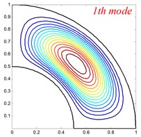
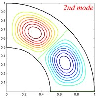
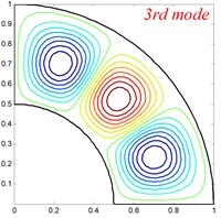
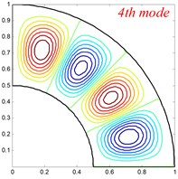
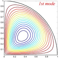
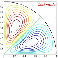
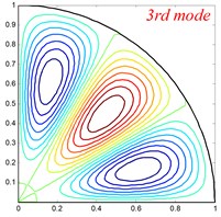
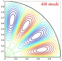
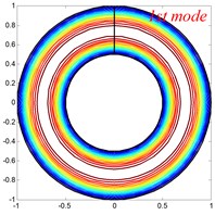
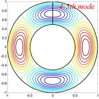
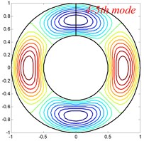
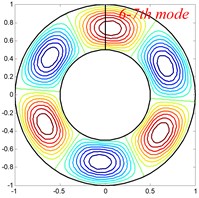
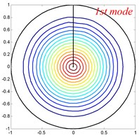
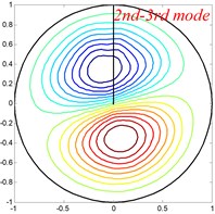
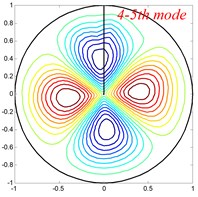
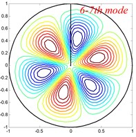
Table 6Comparison of frequency parameters Ω for annular sector plates with different elastic boundary conditions
Method | Mode number | |||||||||
1 | 2 | 3 | 4 | 5 | 6 | 7 | 8 | |||
106 | 106 | present | 0.1621 | 0.1624 | 0.1633 | 0.1654 | 0.1693 | 0.1761 | 0.1867 | 0.2020 |
ABAQUS | 0.1623 | 0.1626 | 0.1635 | 0.1655 | 0.1695 | 0.1762 | 0.1869 | 0.2022 | ||
109 | present | 0.1621 | 0.1624 | 0.1633 | 0.1654 | 0.1694 | 0.1763 | 0.1871 | 0.2025 | |
ABAQUS | 0.1623 | 0.1626 | 0.1635 | 0.1656 | 0.1695 | 0.1764 | 0.1872 | 0.2027 | ||
1012 | present | 0.1621 | 0.1624 | 0.1633 | 0.1655 | 0.1694 | 0.1763 | 0.1871 | 0.2025 | |
ABAQUS | 0.1623 | 0.1626 | 0.1635 | 0.1656 | 0.1695 | 0.1764 | 0.1872 | 0.2027 | ||
106 | 106 | present | 0.1621 | 0.1624 | 0.1633 | 0.1654 | 0.1693 | 0.1761 | 0.1867 | 0.2020 |
ABAQUS | 0.1621 | 0.1624 | 0.1633 | 0.1654 | 0.1693 | 0.1761 | 0.1867 | 0.2020 | ||
109 | present | 0.1624 | 0.1635 | 0.1661 | 0.1706 | 0.1779 | 0.1879 | 0.2017 | 0.2176 | |
ABAQUS | 0.1625 | 0.1637 | 0.1662 | 0.1707 | 0.1778 | 0.1879 | 0.2011 | 0.2175 | ||
1012 | present | 0.1623 | 0.1636 | 0.1663 | 0.1714 | 0.1799 | 0.1925 | 0.2103 | 0.2327 | |
ABAQUS | 0.1626 | 0.1638 | 0.1665 | 0.1715 | 0.1799 | 0.1925 | 0.2101 | 0.2330 | ||
Table 7Comparison of frequency parameters Ω for circular sector plates with different elastic boundary conditions
Method | Mode number | |||||||||
1 | 2 | 3 | 4 | 5 | 6 | 7 | 8 | |||
106 | 106 | present | 0.0148 | 0.0336 | 0.0471 | 0.0578 | 0.0641 | 0.0841 | 0.0979 | 0.1070 |
ABAQUS | 0.0149 | 0.0336 | 0.0470 | 0.0578 | 0.0642 | 0.0845 | 0.0984 | 0.1077 | ||
109 | present | 0.0149 | 0.0340 | 0.0473 | 0.0580 | 0.0643 | 0.0843 | 0.0987 | 0.1073 | |
ABAQUS | 0.0149 | 0.0338 | 0.0472 | 0.0578 | 0.0644 | 0.0848 | 0.0990 | 0.1080 | ||
1012 | present | 0.0149 | 0.0339 | 0.0473 | 0.0580 | 0.0643 | 0.0843 | 0.0986 | 0.1073 | |
ABAQUS | 0.0149 | 0.0338 | 0.0472 | 0.0578 | 0.0644 | 0.0848 | 0.0990 | 0.1080 | ||
106 | 106 | present | 0.0148 | 0.0336 | 0.0471 | 0.0578 | 0.0641 | 0.0841 | 0.0979 | 0.1070 |
ABAQUS | 0.0149 | 0.0336 | 0.0470 | 0.0578 | 0.0642 | 0.0845 | 0.0981 | 0.1077 | ||
109 | present | 0.0295 | 0.0412 | 0.0575 | 0.0759 | 0.0797 | 0.0970 | 0.1080 | 0.1201 | |
ABAQUS | 0.0299 | 0.0410 | 0.0575 | 0.0762 | 0.0802 | 0.0973 | 0.1079 | 0.1209 | ||
1012 | present | 0.0323 | 0.0426 | 0.0588 | 0.0781 | 0.0955 | 0.1001 | 0.1140 | 0.1249 | |
ABAQUS | 0.0324 | 0.0424 | 0.0589 | 0.0784 | 0.0956 | 0.1003 | 0.1140 | 0.1252 | ||
Table 8Comparison of frequency parameters Ω for annular plates with different elastic boundary conditions
Method | Mode number | |||||||||
1 | 2 | 3 | 4 | 5 | 6 | 7 | 8 | |||
106 | 106 | present | 0.0312 | 0.0312 | 0.0312 | 0.0312 | 0.0313 | 0.0315 | 0.0316 | 0.0320 |
ABAQUS | 0.0312 | 0.0312 | 0.0312 | 0.0313 | 0.0313 | 0.0316 | 0.0316 | 0.0321 | ||
109 | present | 0.0372 | 0.0372 | 0.0372 | 0.0373 | 0.0373 | 0.0376 | 0.0376 | 0.0381 | |
ABAQUS | 0.0372 | 0.0372 | 0.0373 | 0.0374 | 0.0374 | 0.0376 | 0.0376 | 0.0382 | ||
1012 | present | 0.0373 | 0.0373 | 0.0373 | 0.0374 | 0.0374 | 0.0376 | 0.0377 | 0.0382 | |
ABAQUS | 0.0373 | 0.0374 | 0.0374 | 0.0375 | 0.0375 | 0.0377 | 0.0377 | 0.0383 | ||
106 | 106 | present | 0.0312 | 0.0312 | 0.0312 | 0.0312 | 0.0313 | 0.0315 | 0.0316 | 0.0320 |
ABAQUS | 0.0312 | 0.0312 | 0.0312 | 0.0313 | 0.0313 | 0.0316 | 0.0316 | 0.0321 | ||
109 | present | 0.0864 | 0.0864 | 0.0864 | 0.0865 | 0.0865 | 0.0867 | 0.0867 | 0.0870 | |
ABAQUS | 0.0865 | 0.0866 | 0.0866 | 0.0867 | 0.0867 | 0.0869 | 0.0869 | 0.0873 | ||
1012 | present | 0.1212 | 0.1212 | 0.1213 | 0.1215 | 0.1215 | 0.1218 | 0.1219 | 0.1225 | |
ABAQUS | 0.1217 | 0.1217 | 0.1217 | 0.1220 | 0.1220 | 0.1224 | 0.1224 | 0.1231 | ||
Table 9Comparison of frequency parameters Ω for circular plates with various elastic boundary supports
Method | Mode number | |||||||||
1 | 2 | 3 | 4 | 5 | 6 | 7 | 8 | |||
106 | 106 | present | 0.0049 | 0.0074 | 0.0074 | 0.0086 | 0.0086 | 0.0108 | 0.0109 | 0.0138 |
ABAQUS | 0.0049 | 0.0074 | 0.0074 | 0.0086 | 0.0087 | 0.0108 | 0.0109 | 0.0138 | ||
109 | present | 0.0053 | 0.0075 | 0.0075 | 0.0088 | 0.0089 | 0.0113 | 0.0115 | 0.0144 | |
ABAQUS | 0.0051 | 0.0075 | 0.0075 | 0.0088 | 0.0090 | 0.0113 | 0.0113 | 0.0146 | ||
1012 | present | 0.0051 | 0.0075 | 0.0075 | 0.0088 | 0.0088 | 0.0113 | 0.0113 | 0.0145 | |
ABAQUS | 0.0051 | 0.0075 | 0.0075 | 0.0088 | 0.0090 | 0.0113 | 0.0113 | 0.0146 | ||
106 | 106 | present | 0.0049 | 0.0074 | 0.0074 | 0.0086 | 0.0086 | 0.0108 | 0.0109 | 0.0138 |
ABAQUS | 0.0049 | 0.0074 | 0.0074 | 0.0086 | 0.0087 | 0.0108 | 0.0109 | 0.0138 | ||
109 | present | 0.0096 | 0.0228 | 0.0228 | 0.0264 | 0.0264 | 0.0319 | 0.0319 | 0.0378 | |
ABAQUS | 0.0100 | 0.0229 | 0.0229 | 0.0264 | 0.0270 | 0.0318 | 0.0320 | 0.0379 | ||
1012 | present | 0.0097 | 0.0236 | 0.0236 | 0.0275 | 0.0275 | 0.0336 | 0.0336 | 0.0400 | |
ABAQUS | 0.0101 | 0.0237 | 0.0237 | 0.0276 | 0. 0276 | 0.0335 | 0. 0335 | 0.0404 | ||
4. Conclusions
As mentioned above, the vibration of orthotropic circular plates, annular plates, and annular, circular sectorial plates was traditionally treated as different boundary value problems, which results in numerous specific solution algorithms and procedures. It is the problem itself that has been an overwhelming task for a new researcher or application engineer to comprehend.
Furthermore, each type of plate usually needs treating separately when different boundary conditions are involved. In order to overcome the above shortcomings, the authors present a unified solution to study the free vibration of the orthotropic circular, annular and sector plate and it breaks through the barriers of different boundary conditions and geometrical shapes. The convergence of the present method is checked through numerical examples and its excellent accuracy and reliability are validated by the comparison with the results obtained by the finite element method. Compared with the most existing methods, the present method has the following highlights:
1) The present method can conduct the vibration analysis for orthotropic circular, annular and sector plates in a unified way.
2) The proposed method is appropriate for general boundary conditions and enables rapid convergence, high reliability and accuracy.
3) The change of the boundary conditions can be easily achieved by only changing the stiffness of the boundary restraint springs along all the edges of plates without involving any change to the solution procedure.
In addition, some new results of the orthotropic circular plates, annular plates, and annular, circular sectorial plates are also reported for the first time, and they may be served as benchmark data for the designers and engineers to avoid the unpleasant, inefficient and structurally damaging resonant.
References
-
Onoe M. Contour vibrations of isotropic circular plates. Journal of the Acoustical Society of America, Vol. 28, Issue 6, 1956, p. 1158-1162.
-
Wang C. M., Thevendran V. Vibration analysis of annular plates with concentric supports using a variant of Rayleigh-Ritz method. Journal of Sound and Vibration, Vol. 163, Issue 1, 1993, p. 137-149.
-
Wang X., Striz A. G., Bert C. W. Free vibration analysis of annular plates by the DQ method. Journal of Sound and Vibration, Vol. 164, Issue 1, 1993, p. 173-175.
-
Mcgee O. G., Leissa A. W., Huang C. S. Vibrations of completely free sectorial plates. Journal of Sound and Vibration, Vol. 164, Issue 3, 1993, p. 565-569.
-
Wang X., Yang J., Xiao J. On free vibration analysis of circular annular plates with non-uniform thickness by the differential quadrature method. Journal of Sound and Vibration, Vol. 184, Issue 3, 1995, p. 547-551.
-
Wang X. W., Wang Y. L. Free vibration analyses of thin sector plates by the new version of differential quadrature method. Computer Methods in Applied Mechanics and Engineering, Vol. 193, Issues 36-38, 2004, p. 3957-3971.
-
Irie T., Yamada G., Ito F. Free vibration of polar-orthotropic sector plates. Journal of Sound and Vibration, Vol. 67, Issue 1, 1979, p. 89-100.
-
Singh Hassan B. S. M. Transverse vibration of a circular plate with arbitrary thickness variation. International Journal of Mechanical Sciences, Vol. 40, Issue 11, 1998, p. 1089-1104.
-
Wong W. O., Yam L. H., Li Y. Y., Law L. Y., Chan K. T. Vibration analysis of annular plates using mode subtraction method. Journal of Sound and Vibration, Vol. 232, Issue 4, 2000, p. 807-822.
-
Wang X. W., Wang Y. L. Re-analysis of free vibration of annular plates by the new version of differential quadrature method. Journal of Sound and Vibration, Vol. 278, Issue 3, 2004, p. 685-689.
-
Houmat A. A sector Fourier p-element applied to free vibration analysis of sectorial plates. Journal of Sound and Vibration, Vol. 243, Issue 2, 2001, p. 269-282.
-
Chen J. T., Chen I. L., Chen K. H., Lee Y. T., Yeh Y. T. A meshless method for free vibration analysis of circular and rectangular clamped plates using radial basis function. Engineering Analysis with Boundary Elements, Vol. 28, Issue 5, 2004, p. 535-545.
-
Seok J., Tiersten H. F. Free vibrations of annular sector cantilever plates. Part 1: out-of-plane motion. Journal of Sound and Vibration, Vol. 271, Issues 3-5, 2004, p. 757-772.
-
Seok J., Tiersten H. F. Free vibrations of annular sector cantilever plates. Journal of Sound and Vibration, Vol. 271, Issues 3-5, 2004, p. 773-787.
-
Aghdam M. M., Mohammadi M., Erfanian V. Bending analysis of thin annular sector plates using extended Kantorovich method. Thin-Walled Structures, Vol. 45, Issue 12, 2007, p. 983-990.
-
Yongqiang L., Jian L. Free vibration analysis of circular and annular sectorial thin plates using curve strip Fourier p-element. Journal of Sound and Vibration, Vol. 305, Issue 3, 2007, p. 457-466.
-
Kim K., Yoo C. H. Analytical solution to flexural responses of annular sector thin-plates. Thin-Walled Structures, Vol. 48, Issue 12, 2010, p. 879-887.
-
Hajabasi M. A., Mirtalaie S. H. Free vibration analysis of functionally graded thin annular sector plates using the differential quadrature method. Proceedings of the Institution of Mechanical Engineers, Part C: Journal of Mechanical Engineering Science, Vol. 225, Issue 3, 2011, p. 568-583.
-
Shi X., Shi D., Li W. L., Wang Q. A unified method for free vibration analysis of circular, annular and sector plates with arbitrary boundary conditions. Journal of Vibration and Control, Vol. 22, Issue 2, 2016, p. 442-456.
-
Li W. L. Free vibrations of beams with general boundary conditions. Journal of Sound and Vibration, Vol. 237, Issue 4, 2000, p. 709-725.
-
Li W. L. Comparison of Fourier sine and cosine series expansions for beams with arbitrary boundary conditions. Journal of Sound and Vibration, Vol. 255, Issue 1, 2002, p. 185-194.
-
Wang Q., Shi D., Shi X. A modified solution for the free vibration analysis of moderately thick orthotropic rectangular plates with general boundary conditions, internal line supports and resting on elastic foundation. Meccanica, 2015, p. 1-33.
-
Shi D., Wang Q., Shi X., Pang F. Free vibration analysis of moderately thick rectangular plates with variable thickness and arbitrary boundary conditions. Shock and Vibration, 2014.
-
Shi D., Wang Q., Shi X., Pang F. An accurate solution method for the vibration analysis of Timoshenko beams with general elastic supports. Proceedings of the Institution of Mechanical Engineers, Part C: Journal of Mechanical Engineering Science, Vol. 229, Issue 13, 2015, p. 2327-2340.
-
Shi D.,Wang Q., Shi X., Pang F. A series solution for the in-plane vibration analysis of orthotropic rectangular plates with non-uniform elastic boundary constraints and internal line supports. Archive of Applied Mechanics, Vol. 85, Issue 1, 2015, p. 51-73.
-
Wang Q., Shi D., Liang Q. Free vibration analysis of axially loaded laminated composite beams with general boundary conditions by using a modified Fourier-Ritz approach. Journal of Composite Materials, 2015, p. 0021998315602138.
-
Wang Q., Shi D., Liang Q., Shi X. A unified solution for vibration analysis of functionally graded circular, annular and sector plates with general boundary conditions. Composites Part B: Engineering, Vol. 88, 2016, p. 264-294.
-
Ye T., Jin G., Chen Y., Ma X., Su Z. Free vibration analysis of laminated composite shallow shells with general elastic boundaries. Composite Structures, Vol. 106, 2013, p. 470-490.
-
Jin G., Ma X., Shi S., Ye T., Liu Z. A modified Fourier series solution for vibration analysis of truncated conical shells with general boundary conditions. Applied Acoustics, Vol. 85, 2014, p. 82-96.
-
Jin G.,Su Z., Shi S., Ye T., Gao S. Three-dimensional exact solution for the free vibration of arbitrarily thick functionally graded rectangular plates with general boundary conditions. Composite Structures, Vol. 108, 2014, p. 565-577.
Cited by
About this article

The authors gratefully acknowledge the financial support from the National Natural Science Foundation of China (No. 51505096), National Natural Science Foundation of China (No. U1430236) and Natural Science Foundation of Heilongjiang Province of China (E2016024).
