Abstract
The article describes the research carried out using a complex numerical model which had been developed applying finite element method (FEM). The supporting structure on which two turbine generators (with a target capacity of approx. 100 kWe) were placed was the object of this study. The calculations were aimed to determine the influence of dynamic properties of the supporting structure on the operation of turbogenerators. Within this study the following tasks have been accomplished: computational modal analysis was performed, the stiffness coefficients of the tested construction were determined and compared with the dynamic properties of the bearings used. This was necessary in order to analyze the dynamic interaction between the rotor and the turbine’s bearings.
1. Introduction
The prototypical ORC installation with a targeted capacity of approx. 100 kWe has been built over the last few years at the Institute of Fluid-Flow Machinery PASci. The core elements of the installation were two independent turbines, which were mounted on the common base frame made from steel profiles. This uncommon supporting structure solution raised serious concerns about the construction stiffness and the values of natural frequencies. The base frame stiffness could have turned out lower than the stiffness of the turbines’ bearings used, which could result in improper operation of the entire ORC installation. Moreover, the shape of the supporting structure indicated that it could have possessed many mode shapes and some of them could have overlapped the natural frequencies of the energy production system. The stiffness of a bearing node can be determined in various ways. In engineering practice, the compliance of a machine foundation is usually a known quantity but there are also the cases described in scientific literature where it was not taken into account in the analysis of a rotating machine. In order to further investigate the dynamic performance of the turbines operating in the ORC installation which was still under construction, dynamic properties of the above-mentioned supporting structure had to be determined. In the course of the research on the frame bearer the method of identification of the model for the supporting structure in a rotating machine was used, described in detail in [1, 2]. The method allowed the numerical determination of dynamic properties of the supporting structure in a system of rotor-bearing-supporting structure type. Subsequently, the model of this structure was verified on the basis of the experimental results [3, 4]. Such a model opens up new research opportunities within the scope of further computer simulations. It can be successfully used for finding diagnostic relations in the framework of the model-based diagnosis, by introducing various types of defects, and then performing computer simulation to get their symptoms [5-7].
2. Research object specification and numerical model
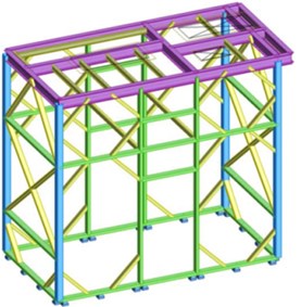
The frame, on which the two turbines and the generator with the electric capacity of 100 kWe were mounted, was the object of this study. The construction was folded using different profiles, marked with different colors in Fig. 1. The square profiles, measuring 120×120×6 mm (RK120×120×6), are colored blue. The rectangular profiles sized 120×60×6 mm (RP120×60×6) and 100×60×5 (RP100×60×5) are colored green and yellow, respectively. The upper part of the structure consists of IPE sections of 200 mm in height (colored violet) and IPE sections of 100 mm in height (colored yellow). The total mass of the frame is about 3363 kg [8]. The upper part of the construction is fitted with a 10 mm welded riffled metal plate that weighs 973 kg. The entire construction is firmly fixed to the floor (using M12 bolts), as shown in Fig. 1.
Fig. 1Visualization of the folded frame showing various profile types
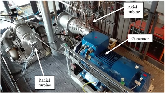
The heaviest components, which are to be mounted on the frame, are the following: two vapor turbines, a generator with belt transmission, an oil storage tank and an oil pump. The axial-flow seven-stage turbine (see Fig. 2) has the rotor shaft which is supported by two types of rolling bearings (radial and angular). Its weight is approximately 240 kg. The asynchronous generator weighing 860 kg is connected to the above-mentioned turbine with a belt transmission, thus creating the first turbogenerator, which was mounted on the additional frame bearer (such as seen in Fig. 2). This frame bearer was made of C120 profiles and was screwed into the main frame with the use of supports made of sheets, measuring 200×250 mm with a thickness of 10 mm. The second turbine with centrifugal radial-flow system weighed 200 kg. The synchronous generator was mounted on the turbine shaft, and the bearing system consisted of two segmented radial bearings and one magnetic thrust bearing.
Fig. 2The ORC turbogenerators with their accessories and measuring devices, placed on the supporting structure
The working medium (low-boiling agent called Octamethyltrisiloxane, also commonly known as MDM) used in the ORC thermal cycle was also successfully applied as a bearing lubricant. This, together with the fact that the generator was situated inside the body, means that this structure was hermetic. The second turbogenerator was also installed on the additional frame bearer made of C120 profiles. The last installation component, which could have affected directly the dynamics of the construction and, indirectly, the turbogenerators, was the oil pump which weighed 450 kg. It was the only element situated below the upper plate, and was mounted directly on the frame. The additional frame bearers for the turbogenerators have a major impact on the mode shapes of the entire frame, as well as on the stiffness of the foundation on which the entire machine was placed. That is why they were taken into account in the numerical model and were treated as one structure.
The entire structure, without taking into account additional elements such as pipeline infrastructure, valves, etc., weighed approx. 6085 kg. The ORC system installation, together with heat exchangers and a regenerator, has been situated on a separate frame. The pipe connections linking turbines or other components attached to the frame naturally have an impact on dynamic characteristics of the machine, but it has been decided that at the present stage of the analysis this impact can be neglected. The pipelines have some elements that are susceptible to thermal expansion (e.g. elongation), which reduces the transmission of vibrations to the entire structure.
Fig. 3Beam finite element model of the supporting structure for ORC turbogenerators (with visible sheathing elements)
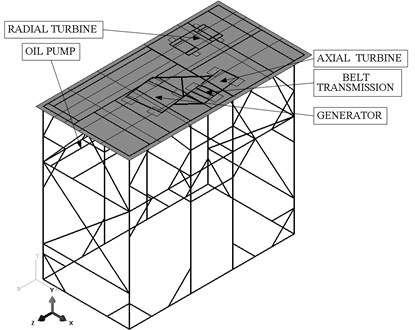
All the above-mentioned elements were included in the model as concentrated mass points at the centre of gravity of each machine and their values corresponded to the actual masses of the devices (Fig. 3). They were connected to the frame model using the wire type finite elements, creating a rigid connection between concentrated mass points. The auxiliary frames were connected to the main frame applying a continuous contact between the mating surfaces (“tie” function). On the other hand, the contact between the framework beams and the main frame’s metal plate was modeled with the functions: “tie” and “rigid body” (surface – nodes/curves). The restraints were created using “displacement/rotation” function, taking away all degrees of freedom, at the points in which the main frame was attached to the foundation [9]. The mesh for finite element analysis was created with adjusting the size of a finite element.
The direction corresponds to the axis lying parallel to the shorter side of the plate as shown in Fig. 3. The direction is perpendicular to the shorter side of the plate, and the line running along the construction height corresponds to the direction.
3. The results of computational modal analysis
The mass of all the devices and the riffled plate was situated on the frame, approximately 4 m above the floor level, and anchored to the frame at several mounting points. The conducted modal analysis gave 200 mode shapes in the frequency range of 0-300 Hz [9]. The first nine mode shapes were related to the four (concentrated) mass points, with all frequency values being close to zero. They were identified as the rotations around the coordinate axes. Those results should be treated as mass points executing rotational motion around their own axes and they do not play any role in practice. The table hereafter (Table 1) lists the frequency values for the first 45 mode shapes of the supporting structure for the ORC system. Looking at the table, it can be noticed that the analyzed structure has numerous natural frequencies which could adversely affect the dynamics of the entire system.
Table 1Natural frequencies corresponding to the first 45 mode shapes obtained during the computational modal analysis
Mode shape no. | Frequency [Hz] | Mode shape no. | Frequency [Hz] | Mode shape no. | Frequency [Hz] |
1 | 6.56 | 16 | 74.66 | 31 | 98.94 |
2 | 15.37 | 17 | 75.61 | 32 | 99.31 |
3 | 21.18 | 18 | 75.87 | 33 | 101.28 |
4 | 34.08 | 19 | 77.65 | 34 | 102.69 |
5 | 35.95 | 20 | 78.01 | 35 | 103.60 |
6 | 38.45 | 21 | 79.87 | 36 | 104.79 |
7 | 44.67 | 22 | 82.47 | 37 | 106.71 |
8 | 57.11 | 23 | 84.68 | 38 | 107.30 |
9 | 59.27 | 24 | 89.75 | 39 | 108.11 |
10 | 61.38 | 25 | 91.49 | 40 | 109.96 |
11 | 61.78 | 26 | 92.35 | 41 | 113.57 |
12 | 64.43 | 27 | 93.02 | 42 | 117.36 |
13 | 68.66 | 28 | 94.49 | 43 | 121.29 |
14 | 72.14 | 29 | 97.88 | 44 | 122.67 |
15 | 73.52 | 30 | 98.39 | 45 | 125.16 |
The nominal rotational speed of the axial-flow turbine is 9000 rpm, which after the conversion of rpm into hertz gives 150 Hz. One of the support structure eigenfrequencies was at 150.02 Hz. Its corresponding mode shape was presented in Fig. 4(a).
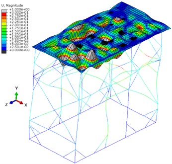
Fig. 4Mode shapes of the supporting structure for the ORC turbogenerators
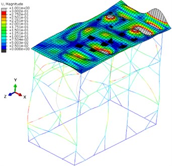
a) 150.02 Hz
b) 234.01 Hz
The auxiliary frames provided significant stiffness at the plate mounting point. The largest displacements occurred at the turbines mounting points and on one edge of the plate. The entire structure made of profiles oscillated in different directions, taking into account the whole analyzed frequency range.
The radial-flow turbogenerator should be resistant against low-amplitude vibrations since it is based on slide bearings which have good damping properties. The rotational speed can be changed between 14 000 rpm and 20 000 rpm (233.3-333.3 Hz) with fixed output power of 80 kWe. This feature of the radial-flow turbo-generator allows to set its operating parameters, in order to prevent any overlap with the natural frequencies of the structure. The exemplary mode shape that appeared at the frequency of 234.01 Hz is presented in Fig. 4(b). It can be observed that the oscillating spots occurred at the spaces of the plate where there are no components of the ORC system. The turbo-generator’s supporting structure also oscillates. The vibration directions of this frame were differentiated according to the mode shape concerned.
4. Measurement of natural frequencies of the turbogenerator
In order to make the results more credible, the measurement of natural frequencies for one of the turbines was conducted. For this measurement, the portable single-channel vibration analyzer was used (Fig. 5). The tested axial-flow turbine was already connected to the whole ORC installation, in consequence the eigenfrequencies (with their corresponding mode shapes) could have changed. The figure below illustrates the characteristics obtained. These results can be regarded as preliminary results since the excitation of the turbine or another element with a large weight to high vibration amplitudes was quite difficult under these conditions. At this point, the turbine mode shapes oscillating only in main directions (-, - and -directions) will be analyzed.
Fig. 5Vibration spectrum obtained after an impact excitation, measured on the axial-flow turbine in the X direction (along the shorter side of the construction)
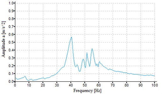
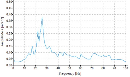
Fig. 6Vibration spectrum obtained after an impact excitation, measured on the axial-flow turbine in the Y direction (along the height of the construction)
The obtained characteristics were presented separately for the three directions, and the values coming from the computational modal analysis are the superpositions of the mode shapes. The comparison of measured eigenfrequencies to the ones received from numerical calculations can be performed using acceleration curves plotted depending on vibration frequency. This is described in more detail in the next part of the article.
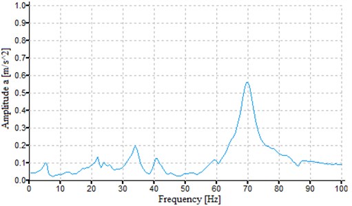
Fig. 7Vibration spectrum obtained after an impact excitation, measured on the axial-flow turbine in the Z direction (along the longer side of the construction)
5. Computational simulation of forced vibration
Simulation analysis of the forced vibration tests was carried out in such a way that the harmonic force with the amplitude of 1000 N was applied to the concentrated masses (that is modeled components of the ORC installation) in the -, - and -directions. This way, the supporting structure was subject to dynamic loads with variable exciting frequency, simulating normal operation of the turbogenerator. It gave the possibility to determine the displacement of the force application point according to the exciting frequency. Next, the dynamic compliance of the structure was found by taking the displacement of the force application point and dividing it by the amplitude of the exciting force. The stiffness of the supporting structure, expressed as the inverse of compliance, was also determined in the three directions. The damping coefficient used for this calculation had the value of 2 %.
5.1. Displacement of the turbogenerators
Fig. 9 presents the displacement graph (in all main directions) for the axial-flow turbine. Additionally, the system’s eigenfrequencies identified by means of simulations were shown in the form of vertical lines (in the range up to 100 Hz). The horizontal axis represents the excitation frequency, and the displacements appear on the vertical axis.
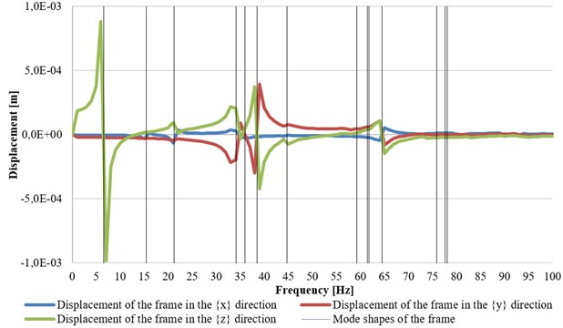
The characteristics of the same type were prepared also for the radial-flow turbogenerator (Fig. 10).
The sudden jump in displacement value and the change of its sign indicate that the excessive vibrations of the supporting structure, called also structural resonance, take place at a given frequency (Fig. 5, Fig. 6). There are also mode shapes not affecting the turbogenerators. The displacement values were similar in both cases. It can be noted that the greatest influence on dynamic performance of the analyzed machines will come from the first and sixth natural frequency of the foundation. The highest values of vibration amplitudes in the direction in the axial turbine occur at the frequency of 38.45 Hz (see displacement plot presented in Fig. 8), which showed good agreement with the measured eigenfrequency value of 40 Hz (Fig. 5). As for the mode shapes of the axial-flow turbine, three of them which were identified in the direction had the following natural frequency values that were quite close to each other: 34.08 Hz, 38.46 Hz, 44.68 Hz (see Table 1). As can be seen in Fig. 6, there are also three maximums with a slightly lower values. The movement of the entire structure (including the turbine) in the direction occurred at the computed frequency of 6.56 Hz, which is in line with the measurement conducted by means of the analyzer (Fig. 8). The difference in the frequency values is only 0.5 Hz. The differences were caused by the fact that the turbine was connected to the heat exchangers using pipelines and valves. The axial-flow turbine was made more rigid in each direction by the presence of the ORC installation. In view of the problems with the vibration excitement, no similar analysis was performed for the second turbogenerator.
Fig. 8The individual x-, y- and z-displacements graphed as a function of the frequency of applied force, with marked eigenfrequencies of the axial turbogenerator
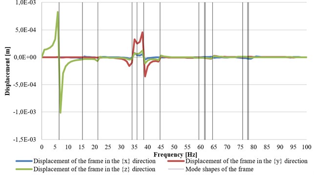
Fig. 9The individual x-, y- and z-displacements graphed as a function of the frequency of applied force, with marked eigenfrequencies of the radial turbogenerator
5.2. Dynamic stiffness of the supporting structure
Figs. 12-14 present the graphs of stiffness of the supporting structure as functions of excitation frequency, obtained for the axial-flow turbine. The stiffness was expressed as the inverse of compliance. Additionally, the lateral stiffness of rolling element bearings (both vertical and horizontal) was presented, corresponding to the planned solution in an axial-flow turbine [10, 11]. The stiffness in the axial direction for that turbine was marked as stiffness in the direction (Fig. 9). For the radial turbogenerator only the obtained values of foundation stiffness were given. The difference in stiffness between the two turbogenerators resulted from various designs of the auxiliary frame. Moreover, the magnetic bearing that was used as thrust bearing has a displacement control system which adjusts the axial clearance between the vanes.
Fig. 10The absolute value of the support stiffness in the X direction
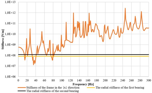
Fig. 11The absolute value of the support’s stiffness in the Y direction
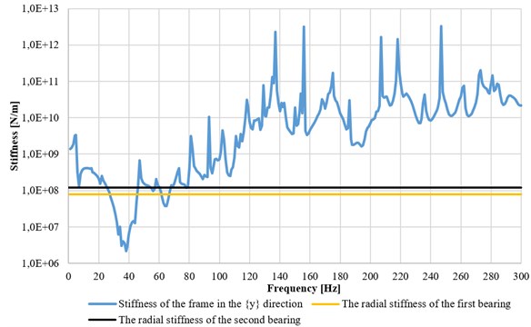
Fig. 12The absolute value of the support’s stiffness in the Z direction
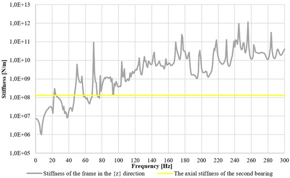
All in all, it may be said that the stiffness in the axial direction is the unknown parameter and its value varies. Only the response time to displacement in the axial direction is very puzzling. The graphs were prepared using a logarithmic scale. The absolute values were presented in the graphs because otherwise at excitation frequencies where the system oscillates with an opposite phase to an excitation force the obtained stiffness values would be less than zero. The stiffness graphs do not look like a typical stiffness characteristic, due to the large number of mode shapes, and the obtained curves were unstable.
Fig. 13Support stiffness in the X, Y and Z directions graphed as function of the frequency of applied force, with marked eigenfrequencies of the axial turbogenerator
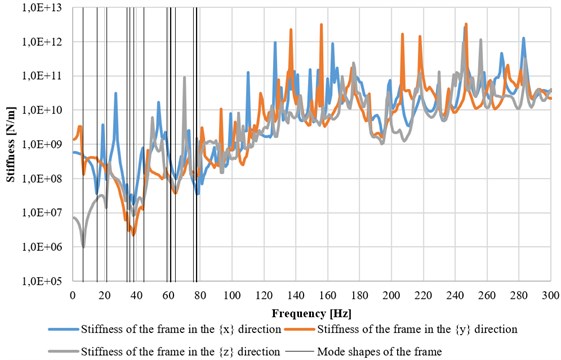
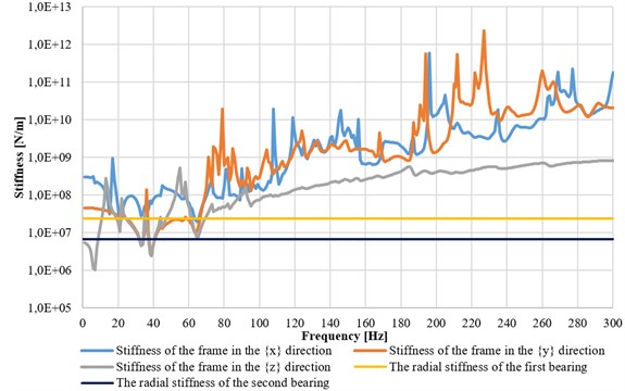
Fig. 14Frame stiffness in the X, Y and Z directions, with marked bearings’ stiffness used in the radial turbogenerator
The foundation stiffness was compared to roller bearings’ stiffness in all directions. It turned out that the foundation of the axial-flow turbine provides the lowest vibration resistance in the low frequency range (up to 80 Hz). The dynamic stiffness of the structure was increasing above this range, which means that the turbine should be capable of stable operation when running with the designed bearing parameters.
The obtained characteristics of the supporting frame for the micro-turbines [12-15] have shown that such a construction was not sufficiently vibration-resistant in the frequency range up to 80 Hz. Moreover, the highest displacements of the entire structure occurred at the frequencies of around 6.5 Hz, 34 Hz and 38 Hz, resulting in the reduction in stiffness value (Fig. 13). The radial-flow turbogenerator provides better dynamic stiffness, as it is based on high-speed externally pressurized bearings – using hydrostatic and hydrodynamic effects (Fig. 14).
6. Conclusions
The article presents the computational simulation results of the dynamic properties of the supporting structure for the ORC installation equipped with vapor-turbine driven generators of the target power capacity of 100 kWe. The loads were applied in such a way as to reflect the excitations coming from the above-mentioned turbogenerators.
Based on the calculation results, the graphs presenting the stiffness of the supporting structure as a function of excitation frequency have been determined. The presented graphs show that the anticipated stiffness of the turbogenerator’s support in the frequency range up to 80 Hz had similar value with the stiffness of the bearings used. It was higher in every direction at 80 Hz and continued to increase along with increasing frequency. It was beneficial in terms of dynamic performance of the rotary system. However, it should be borne in mind that there occurred several lower frequency ranges within which low stiffness of the supporting structure will have the negative impact on the vibration level of the turbo-generator.
Attention should also be paid to several potentially adverse phenomena. The entire supporting structure has a large number of eigenfrequencies, particularly in lower speed ranges, which cause relatively large structural movements. Although rotary systems, both of the turbine and of the generator, are subcritical, but there is a possibility of exciting individual mode shapes of the frame during run-up or coast-down phase. There are several natural frequencies of the frame which are close to the rotational frequency of the axial-flow turbine (150 Hz), and one of them overlaps it perfectly. The turbine operation can therefore excite the vibrations of the supporting structure, and their level depends very much on how the damping in a real unit will be when fully assembled and launched. The rotary system in the second turbogenerator will have more resistance to external factors, because it is equipped with hybrid bearings and a rotational speed adjustment device. These features will allow to find best efficiency point, which means, in particular, the operating point of the turbine at which it is at the maximum efficiency. This operating point will lie somewhere in between the mode shapes of the structure.
Bearing the above in mind, the appropriate diagnostic tests of the assembled system should be performed before starting the turbogenerators (e.g. experimental modal analysis – relatively the simplest method for assessment of the dynamic system properties). The test results produced by use of a harmonic exciter (e.g. the so-called stepped-sinus) can be particularly useful, as they allow for identification of the dynamic properties within a wide range of excitation frequencies. They can indicate possible incorrect presets of some parameters. It is also important to carry out measurements during turbogenerator operation, when the supporting structure is subjected to real operating conditions – during run-up, coast-down as well as when operating at constant speed (at various loads). In case when the machine operates properly at its nominal speed, it is necessary to specify the procedures for run-up and coast-down phases in such a way as to reduce vibration levels coming from the resonances in order to make them as harmless to the machine as possible.
References
-
Żywica G., Rybczyński J. Identification of the model for the supporting structure of a fluid-flow machine. Diagnostics, Vol. 4, Issue 40, 2006, p. 71-76.
-
Żywica G. Modelling of dynamic reaction in system of rotor-bearing-supporting structure type. Machine Dynamics Problems, Vol. 31, Issue 4, 2007, p. 99-109.
-
Żywica G. Simulation investigation of the effect of a supporting structure defect on the dynamic state of the rotor supported on slide bearings. Proceedings of the ASME International Design Engineering Technical Conference and Computers and Information in Engineering Conference, Vol. 1, 2008, p. 1665-1674.
-
Kiciński J., Żywica G. Numerical analysis of defects in the rotor supporting structure. Advances in Vibration Engineering, Vol. 10, Issue 4, 2011, p. 197-204.
-
Cholewa W., Kiciński J. Reverse Diagnostic Models. Technical Diagnostics, Gliwice, 1997.
-
Kiciński J. Modeling and Diagnostics of Mechanical, Aerodynamical and Magnetic Interactions in Energy Turbine Sets. IFFM Publishers, Gdańsk, 2005.
-
Kiciński J. Dynamics of Rotors and Slide Bearings. IFFM Publishers, Gdańsk, 2005.
-
Bagiński P., Żywica G., Kiciński J. Simulation Modal Analysis of the Supporting Structure of a 100 kW Turboset Operating in a Prototypical ORC System at the IFFM PAS Laboratory. Internal Report No. 145/2015.
-
Weiwei X., Kuanmin M., Bin L., Sheng L. Contact stiffness of bolted joint with different material combination in machine tools. Journal of Vibroengineering, Vol. 16, Issue 7, 2014, p. 3281-3293.
-
Żywica G., Kiciński J. Analysis of Dynamical Properties of the Rotor of a Seven-Stage Axial-Flow Steam Micro-Turbine Coupled with an ORC System, Taking into Account Properties of the Supporting Structure. the Assessment of the Risk of Resonance Phenomena at Nominal Speed or during Run Up/Coast Down. IMP PAN, Internal Report No. 494/2014.
-
Żywica G., Breńkacz Ł. Analysis of Dynamical Properties of a 100 kW Micro-Turbogenerator Taking into Account the Belt Transmission and Electric Generator. the Assessment of the Risk of Resonance Phenomena Over the Entire Operational Speed Range. IMP PAN, Internal Report No. 1058/2014.
-
Młyńczak J. Algorithm Determining the Setting Force at Point Machines. Telematics – Support for Transport. Book Series: Communications in Computer and Information Science, Vol. 471, Springer, Heidelberg, 2014, p. 321-330.
-
Kuminek T., Aniołek K., Młyńczak J. A numerical analysis of the contact stress distribution and physical modelling of abrasive wear in the tram wheel-frog system. Wear, Vol. 328, 2015, p. 177-185.
-
Piotrowski B., Gronek A. The design of the test rigs and the turbine disk for the CHP power plant. 2014.
-
The Architectural-Construction Design of the Interchangeable Frame. 2014.
Cited by
About this article

