Abstract
Face gear drives in first-stage gear drives of helicopter main gearboxes occupy several strong points versus traditional spiral bevel gear drives, and are addressed by many scholars. However, face gear vibration suppressions, such as calculation solutions of face gear dynamics associated with tooth profile modifications and influences of tooth profile modifications on face gear dynamic behaviors, are not to be investigated, according to the limited published issues. Thus, in the study, influence mechanisms of two version tooth profile modifications, namely, linear addendum modifications of face gears and arcuate dedendum modifications of pinions, on face gear dynamic base parameters, such as mesh stiffness and static transmission errors, are discussed, and calculation solutions of two version tooth profile modifications are constructed. Meanwhile, an equivalent evaluation solution between linear addendum modifications of face gears and arcuate dedendum modifications of pinions is proposed, and a four degree-of-freedom dynamic model of face gear drives is established. Furthermore, dynamic behaviors of an example case of face gear drives associated with two version tooth profile modifications are simulated. The results indicate dynamic behavior crises of face gear drives would not to be caused by two version tooth profile modifications, and when two version tooth profile modifications are equivalent, the effect of linear addendum modifications of face gears on dynamic mesh force suppressions at whole frequencies is better than that caused by arcuate dedendum modifications of pinions, while, as for mesh frequency, the dynamic mesh force suppression effect caused by arcuate dedendum modifications of pinions is better, and considered dynamic mesh force suppression average values associated with two version tooth profile modifications, arcuate dedendum modifications of pinions are recommended. These contributions would improve modification developments and engineering applications of face gear drives in the future.
1. Introduction
Face gear drives are a kind of intersection gear drives, and addressed by many scholars. There is an extensive body of literatures on face gear drives. Litvin et al. constructed geometry modeling solutions of face gear teeth [1], and discussed tooth contact analysis (TCA) and bending stresses of face gear drives [2; 3]. Barone et. al. assessed the effects of misalignments and tooth profile modifications on TCA of face gear drives [4]. Li et al. proposed a strength calculation solution of face gear drives based on equivalent face gear teeth [5]. Guingand et al. evaluated bending stresses of face gear drives by experiments [6]. Frąckowiak accomplished face gear tooth manufactures by CNC milling machines [7]. David et al. examined tooth surface durability of face gear drives [8]. A team as core of Litvin compiled a design handbook of face gear drives [9], and suggested face gear drives to be employed in first-stage gear drives of helicopter main gearboxes [10], due to insensitive characteristics of manufacture and alignment errors versus spiral bevel gear drives. According to Litvin’s suggestions and operating conditions of first-stage gear drives in helicopter main gearboxes, namely, high speed characteristics, face gear dynamics is focused by researchers. Hu et. al. inspected effects of mesh stiffness on dynamic responses of face gear drives [11]. Jin et al. established a non-linear dynamic model of face gear drives [12]. Yang et al. probed bifurcation characteristics of face gear drives [13, 14]. However, face gear dynamic behavior suppressions are not to be addressed by scholars, and calculation solutions of face gear dynamics associated with tooth profile modifications and influences of tooth profile modifications on face gear dynamic behaviors are not to be investigated, according to the limited published issues. Thus, in the study, influence mechanisms of two version tooth profile modifications, namely, linear addendum modifications of face gears and arcuate dedendum modifications of pinions, on face gear dynamic base parameters, such as mesh stiffness and static transmission errors, are discussed, calculation solutions of two version tooth profile modifications are constructed, an equivalent calculation solution between linear addendum modifications of face gears and arcuate dedendum modifications of pinions, based on a viewpoint of maximum fluctuation values equaled of static transmission errors (STE), is proposed, and a four degree-of-freedom (DOF) dynamic model of face gear drives is established. Furthermore, dynamic behaviors of an example case of face gear drives associated with two version tooth profile modifications are simulated. The results indicate natural frequencies of face gear drives would be reduced by arcuate dedendum modifications of pinions, dynamic behavior crises of face gear drives would not to be caused by two version tooth profile modifications, that is, no any side effects of two version tooth profile modifications on dynamic behaviors of face gear drives would be produced, except vibration suppressions, and when two version tooth profile modifications are equivalent, the effect of linear addendum modifications of face gears on dynamic mesh force suppressions at whole frequencies is better than that caused by arcuate dedendum modifications of pinions, while, as for mesh frequency, the dynamic mesh force suppression effect caused by arcuate dedendum modifications of pinions is better, and considered dynamic mesh force suppression average values associated with two version tooth profile modifications, arcuate dedendum modifications of pinions are recommended. These contributions would benefit to improve developments of tooth profile modifications and engineering applications of face gear drives in the future.
2. Constructed calculation solutions
2.1. Calculation solutions and influence mechanisms of linear addendum modifications of face gears
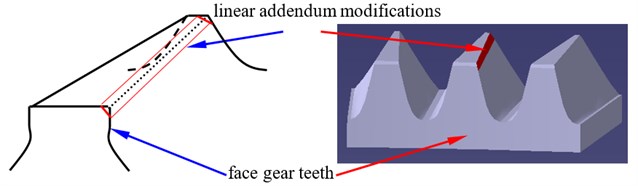
Tooth profile modifications could reduce engagement impacts of face gear drives. Typically, pinions are driving gears, and face gears are driven gears. At engagements, face gear addendum circles would be contacted with pinion dedendum circles. Thus, in order to reduce engagement impacts of face gear drives, two version tooth profile modifications are suggested. One is linear addendum modifications of face gears, namely, addendum straight line modifications of face gears, as shown in Fig. 1.
Fig. 1A sketch of face gear teeth associated with linear addendum modifications
Meanwhile, according to the reference [5], due to point contact transmissions employed by face gear drives, a face gear tooth can be considered as a sequence in which modified involute gears are superimposed along its face width, as shown in Fig. 2.
As illustrated in Fig. 1 and Fig. 2, a linear addendum modification of face gears could be equivalent to that of involute gears, and could be simplified as shown in Fig. 3, according to Ishikawa model [15].
According to the reference [15], each part flexibility of Ishikawa model can be calculated, as listed in Table 1.
Fig. 2A sketch of an equivalent face gear tooth
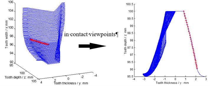
Fig. 3A sketch of an equivalent linear addendum modification of face gear teeth
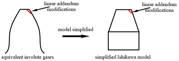
Table 1each part flexibility calculation equations of Ishikawa model
Symbol | Calculation equations |
The symbols ,, ,, and are a bending flexibility of the rectangle part, a bending flexibility of the trapezoid part, a shear flexibility, a contact flexibility, and the flexibilities induced by base rotations of teeth and rotations of wheel bodies, respectively, is a modulus of elasticity, is a Poisson ratio, and are tooth numbers, and are rim diameters, and are reference circle diameters of pinions and face gears, respectively, is a drive ratio, as well as , and , , are an acting angle and the geometry parameters of gears, which can be expressed as [15]:
where subscript , , and express mesh point positions, base circles, dedendum circles, and addendum circles, respectively, is a tooth thickness, is a reference circle radius, is a pressure angle, and is a width of minimum life sections.
As given in Fig. 1 to Fig. 3, face gear addendum thicknesses would be decreased by linear addendum modifications of face gears. Meanwhile, according to Eq. (1), only geometry parameter could be affected by addendum thicknesses, and only two flexibilities, namely, and , which occupy smaller proportions of flexibility sum values based on engineering experiences, would be affected by , according to the flexibility calculation equations, as listed in Table 1. Thus, mesh stiffness of face gear drives is almost not to be impacted by linear addendum modifications of face gears, due to mesh stiffness being a reciprocal of flexibility sum values of face gear drives. However, static transmission errors of face gear drives would be affected, due to a mesh error increase caused by the modification, which is the component of STE and could be equivalent as shown in Fig. 4.
Fig. 4A sketch of equivalent tooth form deviations of linear addendum modifications
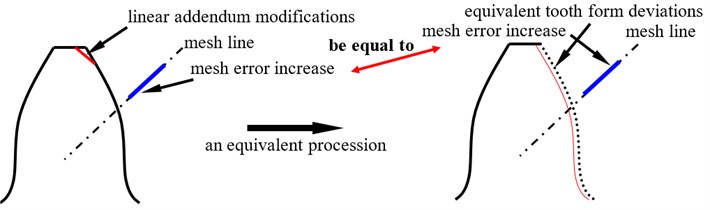
As illustrated in Fig. 4, a mesh error increase caused by linear addendum modifications of face gears could be defined as:
where is a maximum value of linear addendum modifications of face gears, and is a percentage of modification lengths versus base pitches.
2.2. Calculation solutions and influence mechanisms of arcuate dedendum modifications of pinions
The other version tooth profile modification is arcuate dedendum modifications of pinions, as shown in Fig. 5.
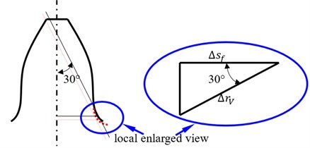
As given in Fig. 5, minimum life sections of pinions would be affected by arcuate dedendum modifications, and the width variation of minimum life sections, as shown in Fig. 6, could be derived by:
where is a width variation of minimum life sections, is a fillet radius maximum variation of pinions caused by arcuate dedendum modifications.
According to the equations, as listed in Table 1, and Eq. (1), tooth flexibilities of pinions would be impacted by minimum life section width changes. Thus, both mesh stiffness and STE would be affected by arcuate dedendum modifications of pinions.
Fig. 5A sketch of pinion teeth associated with arcuate dedendum modifications
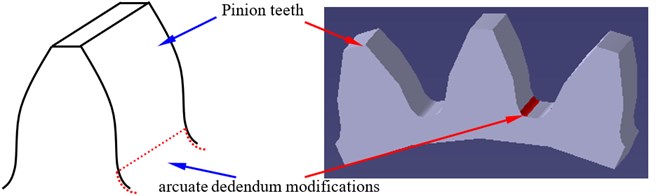
Fig. 6A sketch of variations of minimum life sections of pinions
2.3. An equivalent evaluation solution of two version tooth profile modifications
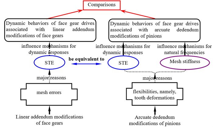
The difference of two version tooth profile modifications on face gear dynamics can be expressed, as shown in Fig. 7.
As illustrated in Fig. 7, in order to asses influences of two version tooth profile modifications on face gear dynamic behaviors, an equivalent evaluation solution of two version tooth profile modifications, based on the viewpoint of maximum fluctuation values equaled of STE, could be defined as:
where is a maximum fluctuation value of STE associated with linear addendum modifications of face gears, is a maximum fluctuation value of STE associated with arcuate dedendum modifications of pinions, is a maximum fluctuation value of STE, is a maximum amplitude, is a minimum amplitude, is a STE, is a comprehensive mesh error, as well as and , which could be calculated according to the equations listed in Table 1, are tooth deformations of face gears and pinions, respectively.
Fig. 7A diagram of the difference between two version profile modifications
2.4. Four DOF dynamic model
In order to compare linear addendum modifications of face gears with arcuate dedendum modifications of pinions on dynamic behaviors of face gear drives, a four DOF dynamic model of face gear drives is formulated, as shown in Fig. 8.
Fig. 8A four DOF dynamic model of face gear drives
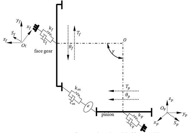
In Fig. 8 subscript and express face gears and pinions, respectively, is a torsion degree, is a bending degree, is a torsion, is a bending stiffness, is a bending damping, is a mesh stiffness, is a mesh damping, and is a shaft angle.
As given in Fig. 8, the mathematic equations of the dynamic model could be derived by:
where is a quality, is a base circle radius, is a moment of inertia, and could be deduced as:
3. Simulation and analysis
3.1. STE simulation and analysis
In order to evaluate dynamic behavior differences of face gear drives associated with two version tooth profile modifications, geometry parameters, material parameters, operating conditions, and modification parameters of linear addendum modifications of face gears, which are determined by the reference [16] and working experiences, of an example case of face gear drives are listed in Table 2.
Table 2Parameters of an example case
Names | Values | Units | |
Geometric parameters | Modulus | 2.5 | mm |
Pressure angle | 22.5 | ° | |
Tooth number of pinions | 23 | – | |
Tooth number of face gears | 77 | – | |
Shaft angle | 90 | ° | |
Addendum coefficient | 1 | – | |
Clearance coefficient | 0.25 | – | |
Operating conditions | Power | 50 | kW |
Input rotation speed | 4000 | r/min | |
Material characteristics | Modulus of elasticity | 210000 | MPa |
Poisson ratio | 0.3 | – | |
Addendum modifications | Maximum modification value | 15 | μm |
Percentage of modification lengths versus base pitches | 25 | % |
According to the parameters listed in Table 2, the equations listed in Table 1, Eq. (2) and Eq. (4), STE without any modifications and that associated with linear addendum modifications of face gears are simulated, as shown in Fig. 9.
In the case of Fig. 9, the amplitudes of STE associated with linear addendum modifications of face gears versus engagement-in-and-out positions are less than those without any modifications, but the phenomenon is opposite versus pitch positions. According to Eq. (4), the STE maximum fluctuation values, as shown in Fig. 9, are calculated in Table 3.
Table 3STE maximum fluctuation values in Fig. 9
maximum fluctuation values | Unit | |
Without any modifications | 366.74 | μm |
With linear addendum modifications of face gears | 361.8 |
A maximum fluctuation value difference between two STE simulation results could be defined as:
where subscript 1 and 2 express two STE simulations, respectively.
Fig. 9STE simulations of the example case
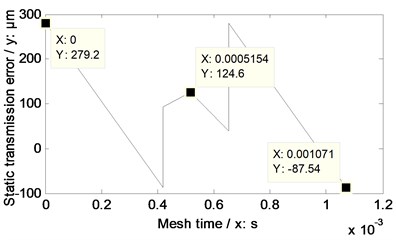
a) Without any modifications
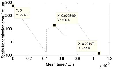
b) With linear addendum modifications of face gears
According to the results listed in Table 3 and Eq. (7), the maximum fluctuation value difference between without any modifications and with linear addendum modifications of face gears of the example case of face gear drives is 1.35 %.
According to the proposed equivalent evaluation solution of two version tooth profile modifications, namely, Eq. (4), and the simulated STE maximum fluctuation value associated with linear addendum modifications of face gears, an arcuate dedendum modification value of pinions of the example case, and a STE and the STE maximum fluctuation value associated with the modification are calculated and simulated, as shown in Table 4 and Fig. 10, respectively.
Table 4A Modification value and STE maximum fluctuation value associated with the modification
Values | Unit | |
Arcuate dedendum modification of pinions | 30 | μm |
STE maximum fluctuation with arcuate dedendum modifications of pinions | 361.9 | |
Maximum fluctuation value difference between two version tooth profile modifications | 0.0276 | % |
Fig. 10STE simulation associated with arcuate dedendum modifications of pinions
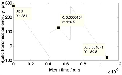
In the case of Fig. 10, the amplitudes of STE associated with arcuate dedendum modifications of pinions versus engagement-in-and-out positions is greater than that associated with linear addendum modifications of face gears, while, the amplitudes of STE simulation results of two version tooth profile modifications versus pitch positions are the same.
3.2. Mesh stiffness and natural frequency simulation and analysis
Mesh stiffness and natural frequencies of face gear drives associated with linear addendum modifications of face gears are equal to those without any modifications, due to mesh stiffness of face gear drives not being impacted by linear addendum modifications of face gears.
According to the parameters listed in Table 2 and the equations listed in Table 1, the mesh stiffness of the example case of face gear drives without any modifications and associated with two version tooth profile modifications are simulated, as shown in Fig. 11.
Fig. 11Mesh stiffness simulations of the example case
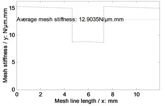
a) Without modifications / With linear addendum modifications
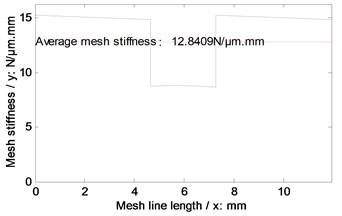
b) With arcuate dedendum modifications
Introducing the mesh stiffness, as given in Fig. 11, into Eq. (5), the natural frequencies of the example case of face gear drives associated with two version tooth profile modifications are simulated, as shown in Fig. 12.
Fig. 12Natural frequency simulations of the example case
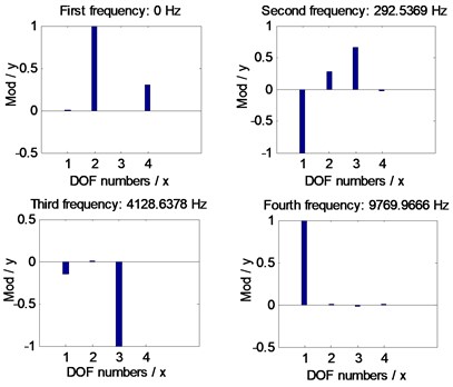
a) Without modifications / With linear addendum modifications
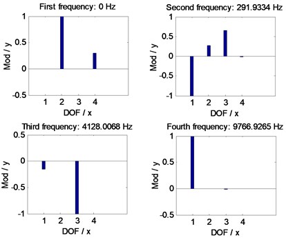
b) With arcuate dedendum modifications
In the case of Fig. 11 and Fig. 12, the average mesh stiffness and natural frequencies of the example case of face gear drives associated with arcuate dedendum modifications of pinions is less than those with linear addendum modifications of face gears, due to minimum life section width reductions caused by arcuate dedendum modifications of pinions.
3.3. Simulation and analysis of relationships between accelerations and velocities
The relationships between accelerations and velocities of the example case of face gear drives without any modifications and associated with two version tooth profile modifications are simulated, as shown in Fig. 13, by introducing the STE simulation results, as shown in Fig. 9 and in Fig. 10, into Eq. (5).
As illustrated in Fig. 13, whatever linear addendum modifications of face gears or arcuate dedendum modifications of pinions would not cause dynamic behavior crises of face gear drives, that is, except vibration suppressions, not any side effects of dynamic behaviors of face gear drives could be produced by such two version tooth profile modifications.
Fig. 13Relationships between accelerations and velocities of the example case simulated
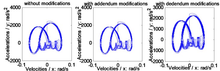
a) On the pinion
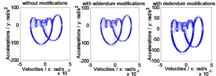
b) On the face gear
3.4. Dynamic mesh force simulation and analysis
In order to evaluate the effects of two version tooth profile modifications on dynamic mesh force suppressions of face gear drives, the dynamic mesh forces of the example case of face gears without any modifications and associated with two version tooth profile modifications are simulated, as shown in Fig. 14.
In the case of Fig. 14, the suppressions of two version tooth profile modifications on dynamic mesh forces of face gear drives are effective. Meanwhile, the dynamic mesh force suppression effect differences of two version tooth profile modifications of the example case of face gear drives could be expressed as curves, which could be defined as amplitude differences between one of tooth profile modifications and without any modifications versus frequencies, as shown in Fig. 15.
According to Fig. 15, an average value of suppressions could be defined as:
where is an average value of suppressions, is an amplitude of suppression curves versus frequencies, is a number of frequencies.
Fig. 14Dynamic mesh forces of the example case simulated
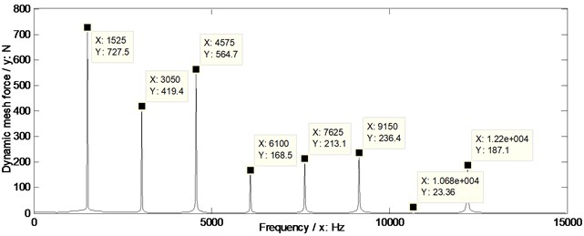
a) Without any modifications
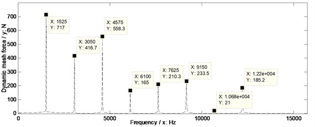
b) With linear addendum modifications of face gears
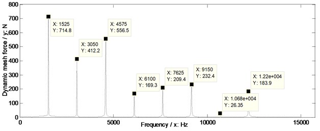
c) With arcuate dedendum modifications of pinions
Fig. 15Suppression effect comparisons of two version tooth profile modifications of the example case
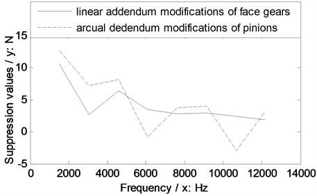
According to the results, as shown in Fig. 15, the average values of suppressions of two version tooth profile modifications of the example of face gear drives are calculated as listed in Table 5.
Based on the limited simulation results in the issue, as shown in Fig. 15, when two version tooth profile modifications are equivalent, the suppression effect of the linear addendum modification of face gears on dynamic mesh forces of face gear drives is better than that caused by arcuate dedendum modifications of pinions at whole frequencies. While, the suppression effect of the linear addendum modification of face gears on dynamic mesh forces of face gear drives is worse than that caused by arcuate dedendum modifications of pinions at the mesh frequency. Considered the suppression average values of two version tooth profile modifications on dynamic mesh forces of the example case of face gear drives, and dynamic mesh force suppression effects at the mesh frequency, the arcuate dedendum modification of pinions is recommended for face gear drives.
Table 5Average values of suppressions of the example case
Average values | Unit | |
With linear addendum modifications of face gears | 4.13 | N |
With arcuate dedendum modifications of pinions | 4.40 |
4. Conclusions
In the study, three important works could be extracted as follows:
1) The calculation solutions of two version tooth profile modifications, namely, linear addendum modifications of face gears and arcuate dedendum modifications of pinions, are constructed, and influence mechanisms of two version tooth profile modifications on dynamic behaviors are discussed.
2) An equivalent evaluation solution of two version tooth profile modifications is proposed, based on the viewpoint of STE maximum fluctuation values equaled.
3) Dynamic behaviors of an example case of face gear drives associated with two version tooth profile modifications are simulated. The results indicate two version tooth profile modifications would not generated any side effects of dynamic behaviors, except vibration suppressions, and linear addendum modifications of face gears is better than arcuate dedendum modifications of pinions at whole frequencies, while, the assessment is opposite at the mesh frequency. In addition, considered dynamic mesh force suppression average values of two version tooth profile modifications, and suppression effects at the mesh frequency, which is the most important frequency of gear drives, the arcuate dedendum modification of pinions is recommended.
These contributions would benefit to improve developments of face gear modifications and engineering applications of face gear drives in the future.
References
-
Litvin F., Bossler R., Chen Y.-J., Zhang Y., Wang J.-C. Design and geometry of face-gear drives. Journal of Mechanical Design, Vol. 114, Issue 4, 1992, p. 642-647.
-
Litvin F. L., Fuentes A., Howkins M. Design, generation and TCA of new type of asymmetric face-gear drive with modified geometry. Computer Methods in Applied Mechanics and Engineering, Vol. 190, Issue 43, 2001, p. 5837-5865.
-
Litvin F. L., Fuentes A., Zanzi C., Pontiggia M. Design, generation, and stress analysis of two versions of geometry of face-gear drives. Mechanism and Machine Theory, Vol. 37, Issue 10, 2002, p. 1179-1211.
-
Barone S., Borgianni L., Forte P. Evaluation of the effect of misalignment and profile modification in face gear drive by a finite element meshing simulation. Journal of Mechanical Design, Vol. 126, Issue 5, 2004, p. 916-924.
-
Zhengminqing Li, Hao Wu, Rupeng Zhu Influence predictions of geometric parameters on face gear strength. Advances in Mechanical Engineering, Vol. 7, Issue 3, 2015, p. 1-7.
-
Guingand M., De Vaujany J.-P., Jacquin C.-Y. Quasi-static analysis of a face gear under torque. Computer Methods in Applied Mechanics and Engineering, Vol. 194, Issue 39, 2005, p. 4301-4318.
-
Frąckowiak P. Modelling and cutting a face-gear with straight line on CNC milling-machine. Manufacturing Engineering, Vol. 9, Issue 3, 2010, p. 19-21.
-
David G. Lewicki, G. F. H., Robert R. Filler, Stephen C. Slaughte, Jason Fetty RDS-21 face-gear surface durability tests. Forum 63 sponsored by the American Helicopter Society International (AHS), Virginia, 2007.
-
Litvin F. L., Egelja A., Tan J., Chen D., Heath G. Handbook on Face Gear Drives with a Spur Involute Pinion. DTIC Document, 2000.
-
Litvin F., Bossler R., Chen Y.-J., Lewicki D., Heath G., Wang J.-C. Application of face-gear drives in helicopter transmissions. Journal of Mechanical Design, Vol. 116, Issue 3, 1994, p. 672-676.
-
Hu Z. H., Tang J. Y., Chen S. Y., Lei D. C. Effect of mesh stiffness on the dynamic response of face gear transmission system. Journal of Mechanical Design, Vol. 135, Issue 7, 2013, p. 1-7.
-
Jin G., Zhu R., Bao H. Nonlinear dynamical characteristics of face gear transmission system. Journal of Central South University (Sci Technol), Vol. 5, Issue 41, 2010, p. 1807-1813, (in Chinese).
-
Yang Z., Wang S.-M., Fan Y.-S., Liu H.-X. Bifurcation charactristics of face-gear transmission system. Journal of Harbin Institute of Technology, Vol. 3, Issue 43, 2011, p. 107-110, (in Chinese).
-
Yang Z., Wang S.-M., Fan Y.-S., Liu H.-X. Vibration characteristics of face-gear transmission system with parametric excitation. Journal of Chongqing University, Vol. 35, Issue 1, 2011, p. 26-35, (in Chinese).
-
Shi J. L., Ma X. G., Xu C. L., Zang S. J. Meshing stiffness analysis of gear using the Ishikawa method. Applied Mechanics and Materials, Vol. 401, 2013, p. 203-206.
-
Song Lemin Gear Tooth Surfaces and Strengths. National Defend Industry Press, Beijing, 1987, p. 18-230, (in Chinese).
Cited by
About this article

The authors are grateful for the financial support provided by the National Natural Science Foundation of China under No. 51105194 and No. 51375226, and the Fundamental Research Funds for the Central Universities under No. NS2015049. In addition, the authors declare that there is no conflict of interests regarding the publication of this article.
