Abstract
A novel transmission using the multistage face gears as the core component is used to realize variable speed with differential gear shifting, there are multiple face gears superimposed on the radial direction, meshing with planetary wheel at the same time, which achieves different outputs speed through braking different face gears. In order to solve the interference problems caused by asynchronous meshing motion between several face gears and the same cylinder gear, this study mainly focuses on the meshing theory study based on the double crown surfaces in tooth profile and tooth orientation. The surface structure of straight tooth and double crown are constructed according to the related surface equations, the corresponding interference conditions are obtained by comparison, every single stage face gear model is designed and assembled. This study shows that the double crown configuration surface structure can easily improve contact characteristics compared with straight tooth surface structure of face gear. In addition, the double crown configuration surface structure can improve the distribution and direction of contact path. This study is expected to establish a new tooth surface model, which can provide the best machining parameters for the face gears.
1. Introduction
The core component of the novel multistage face gears transmission is the planetary gear train meshed by multistage face gears and cylindrical gear. The face gear driving is a new type of power transmission technology and contains many advantages such as big transmission ratio, small gear axial force and insensitiveness to the axial installation error, excellent distributary feature, all of which can optimize the size and weight of the transmission system greatly with higher reliability. Since face gear was developing continuously, Ref. [1] carried out a systematic and meticulous research on the face gear from the initial of the mesh geometry principle. After that, Ref. [2] also had an in-depth and extensive research based on the related results of face gear driving. Besides, Ref. [3-5] researched in terms of meshing principle or movement characteristics of face gear. Based on the results in geometry design method, transmission error, contact theory and meshing performance, etc., this study aims to optimize the meshing equation, crown surface configuration technology and structure design of multistage face gears by theoretical analysis and software simulation, which can improve contact features and avoid motion interference. The feasibility of double crown configuration is verified through the successful trial produced by the samples.
2. Meshing principle of the novel transmission system
The space structure of multistage face gears and cylindrical gear belongs to the orthogonal mesh, the elastic deformation caused by tooth surface stress in the process of meshing may deviate the mesh point trajectory from the theoretical mesh curve. In addition, the contact between face gears and cylindrical gear is difficult to be synchronized due to the tooth number differences, which leads to the edge contact interference between two levels and exists a big stress concentration, so it is easy to cause a mutual interference problem in the transmission process.
According to the relative motion relation,face gear pairs are described with four coordinate systems, the intersection point between cylindrical gear rotation axis and the face gear rotation axis are the origin of coordinates, which is shown in Fig. 1.
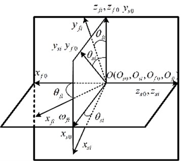
In order to ensure the correctness of the relative position and relative movement in coordinate transformation, it is needed to set up a transformation matrix from cylindrical gear coordinate system to the face gear coordinate system, Ref. [6], shown in Fig. 2.
Fig. 1The coordinate system of face gears
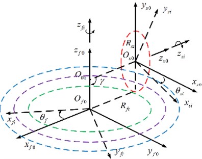
Fig. 2The transformation coordinate system of the face gears
Setting as the vertical section, the tooth face equation of gear shaper cutter involute is obtained:
In Eq. (1), is the base radius of cylindrical gear, is the modulus, is tooth number, is pressure angle. is the axial parameters of one point in cylindrical gear tooth surface. is angle parameters of one point on the cylindrical gear involute. is the angle parameters from alveolus symmetrical line to involute starting point. , is involute function of the pressure angle , .
The conjugate surfaces between two gears refer to a pair of teeth surface that satisfy the meshing motion and must be continuously tangent under the given motion pattern at contact points, Ref. [7]. Conjugate surface can be obtained from one to the other through the envelope principle in the given motion pattern of the two gears.
By meshing equation, the tooth surface equation of face gear as follows:
In Eq. (2), . The tooth surface equation corresponding to multistage face gears can be acquired when choosing different face gears , , as in .
The difference of normal curvatures of a pair of conjugate surfaces at one point of contact along any tangent lines is called the induced curvature of the direction. It reflects the degree of closeness of the two conjugate surfaces in the meshing, which is the important factor to determine the size of contact, Ref. [8]. Assumption that the radius of normal curvature at any point of tooth surface along the direction is . Two different solutions and of radius of principal curvature can be obtained from solving the above equation, so and are two principal curvatures:
Reference to the calculation analysis of induced normal curvature, we define the common normal direction as the space directed by the gear tooth entity. It is known from Table 1:
1) The main curvature of the face gear outer radius along the length of tooth is smaller, the inner radius’s main curvature is significant changes, but the value is much smaller to indicate that the tooth surface is relatively flat.
2) The larger principal value of the induced normal curvature is much bigger than the smaller principal value, and the numerical value is determined mainly by the principal curvature of the cylindrical gear.
3) If there is no curvature interference in two teeth surfaces, the induced normal curvature of and must be negative in any direction.
Table 1The curvature parameters of meshing point of face gear conjugate surface
Mesh point | Angle of cylindrical gear | Main curvature of cylindrical gear | Main curvature of face gear | Induced principal curvature | Induced curvature | |||
1 | 0.1000 | –0.5263 | 0 | –0.3231 | 0.0725 | –0.2032 | –0.0725 | –0.2019 |
2 | 0.1349 | –0.3901 | 0 | –0.2555 | 0.0696 | –0.1347 | –0.0696 | –0.1310 |
3 | 0.1698 | –0.3099 | 0 | –0.2102 | 0.0666 | –0.0998 | –0.0666 | –0.0952 |
4 | 0.2047 | –0.2571 | 0 | –0.1776 | 0.0634 | –0.0795 | –0.0634 | –0.0756 |
5 | 0.2396 | –0.2196 | 0 | –0.1529 | 0.0600 | –0.0668 | –0.0600 | –0.0642 |
6 | 0.2745 | –0.1917 | 0 | –0.1334 | 0.0566 | –0.0583 | –0.0566 | –0.0574 |
7 | 0.3094 | –0.1701 | 0 | –0.1176 | 0.0530 | –0.0525 | –0.0530 | –0.0528 |
8 | 0.3443 | –0.1528 | 0 | –0.1043 | 0.0494 | –0.0485 | –0.0494 | –0.0492 |
9 | 0.3793 | –0.1388 | 0 | –0.0930 | 0.0457 | –0.0458 | –0.0457 | –0.0457 |
10 | 0.4491 | –0.1172 | 0 | –0.0743 | 0.0384 | –0.0429 | –0.0384 | –0.0384 |
3. Double crown profile configuration of face gear
The purpose of double crown configuration is to improve the meshing contact area between cylindrical gear and face gear in the position of face gear tooth surface to avoid the phenomenon in face gear, such as stress concentration, partial load and interference. In order to obtain the precise crown surfaces in tooth profile and tooth orientation, the double crown surface configuration of face gear is reconstructed from the straight tooth surfaces reconfiguration of cylindrical gear.
The tooth profile crown is a parabolic reconstruction from tooth addendum direction to tooth root direction, Refs. [9]. The cylindrical gear tooth profile crown is composed of approximate parabola, with that the central of tooth thickness is parabolic virtual center, is radius, is vertex position parameter of tooth profile parabola, is surface parameters in the direction of tooth profile. is profile parabola deformation, is profile parabola coefficient.
The equation of the parabolic crown surface of any tooth profile as follows:
Introducing the transformation of generating gear coordinate system, so the surface equation of generating gear as follows:
The tooth orientation crown configuration is to gradually reduce the thickness of the tooth thickness toward both ends of the gear tooth, introducing a virtual cutter gear, and then assuming that the cutter can realize cylindrical gear tooth orientation configuration with a parabolic trajectory along the tooth length. Supposing that the orientation projection crown is composed of parabolic and mirror curves, with that the central of tooth thickness is parabolic virtual center, is radius, is surface parameters in the direction of tooth profile . is profile parabola deformation, is profile parabola coefficient.
The parabola silhouette in tooth orientation direction is the transverse silhouette of the generating gear, that is . So, the lateral section silhouette of virtual cutter is:
The surface equation of cylindrical gear double crown profile configuration can be obtained from the coordinate transformation relation between the virtual cutter and the double crown cylindrical gear as follows:
In Eq. (7), is the parabolic vertex position parameters.
According to the coordinate transformations and envelop relationships, the double crown surface equation of face gears is derived:
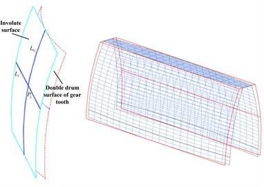
It is difficult to construct the model accurately with single 3D drawing software because of the complexion about the double crown surfaces configuration of face gear. Based on Matlab software for mediation, this study can calculate the point coordinates of the tooth surface more accurately, and then import the corresponding coordinate value into 3D software, so that can carry out the complete surface structure modeling of face gear. The configuration effect is shown in Fig. 3-4.
Fig. 3Drum configuration surface crowing a) of tooth profile, b) of longitudinal tooth
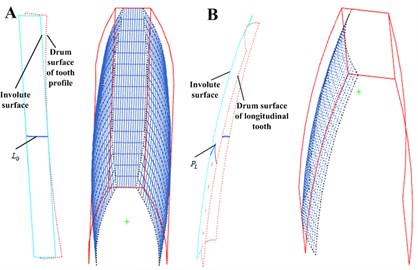
Fig. 4Double drum configuration surface crowing of gear tooth
4. NC machining brief analysis about crown surface of face gear
Compared with the common gear hobbing or forming machining method, the NC machining is more suitable for the development of single, small batch production and new products. In addition, it can also process the complicated surface. In this paper, the machining of face gears is only used for sample development and experimental research, which belongs to small batch or single unit production. In order to improve the processing efficiency and ensure the quality of processing, it is divided into two working procedure, roughing and finish machining. For example, flat end milling cutter is used in rough machining, as shown in Fig. 5(a, b). And ball end milling cutter is used in finish machining, as shown in Fig. 5(c).
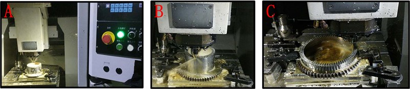
The face gears samples can be processed by CARVER 5400. Starting from the blank workpiece, after 3 processing of ‘Firstly roughing’, ‘Angle clearing’ and ‘Shiny processing’, and carrying out the surface treatment with nitrification. In the same way, all the required multistage face gears are processed separately, as shown in Fig. 6.
Fig. 5Cutter path of cavity milling for: a) firstly roughing, b) angle clearing, and c) cutter path of contour milling for shiny processing
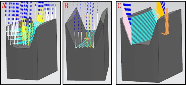
Fig. 6Milling machining: a) of level 1 face gear sample, b) of level 2 face gear sample, c) of level 3 face gear sample
5. Conclusions
The multistage face gears as the core component of a novel transmission realize variable speed with differential gear shifting. The study solves the problem of the meshing of multistage face gears that lays the foundation for the following research:
1) Setting up a multistage face gears meshing coordinate system to obtain the relation of each coordinate by the space coordinate transformation principle, and then the cutter tooth surface equation and the parametric equation of relative speed of contact points are derived. Thus, the parametric equations of multistage face gears are derived based on the conjugating theory.
2) Setting up a judging equation of surface interference, then studying the limit conditions of multistage face gears such as motion interference, and therefore obtaining the range of tooth surface equation. But it is more complicated to derive the tooth surface equation of face gear directly. Therefore, the tooth surface equation of the double crown configuration can be derived by the crown reconstruction of the cutter, and the tooth surface equation of the face gear is obtained through the enveloping surface.
3) A series of coordinate points of crown surface are constructed by MATLAB, and then the 3D entity and assembly model of multistage face gears are obtained by UG 3D modeling function to realize the visualization of multistage face gears.
4) This study briefly describes the design analysis method and process manufacturing method of a novel multistage transmission sample, which are prepared conditions for subsequent experimental studies.
References
-
Lin C., Cai Z. Q. Modeling of dynamic efficiency of curve-face gear pairs. Proceedings of the Institution of Mechanical Engineers Part C-Journal of Mechanical Engineering Science, Vol. 230, Issue 7, 2016, p. 1209-1221.
-
Liu D. W., Wang G. H., Ren T. Z. Transmission principle and geometrical model of eccentric face gear. Mechanism and Machine Theory, Vol. 109, 2017, p. 51-64.
-
Chung T.-D., Chang Y.-Y. An investigation of contact path and kinematic error of face-gear drives. Journal of Marine Science and Technology, Vol. 13, Issue 2, 2005, p. 97-104.
-
Ming X. Z., Gao Q., Yan H. Z., Liu J. H., Liao C. J. Mathematical modeling and machining parameter optimization for the surface roughness of face gear grinding. International Journal of Advanced Manufacturing Technology, Vol. 90, Issues 9-12, 2017, p. 2453-2460.
-
Saribay Z. B. Tooth geometry and bending stress analysis of conjugate meshing face-gear pairs. Proceedings of the Institution of Mechanical Engineers Part C-Journal of Mechanical Engineering Science, Vol. 227, Issue 6, 2013, p. 1302-1314.
-
Lin C., Wu X. Y. Calculation and analysis of contact ratio of helical curve-face gear pair. Journal of the Brazilian Society of Mechanical Sciences and Engineering, Vol. 39, Issue 6, 2017, p. 2269-2278.
-
Saribay Z. B., Bill R. C., Smith E. C., Rao S. B. Geometry and kinematics of conjugate meshing face-gear pairs. Journal of the American Helicopter Society, Vol. 62, Issue 3, 2017, p. 1-10.
-
Zhao Y. P., Zhang Y. M. Computing method for induced curvature parameters based on normal vector of instantaneous contact line and its application to Hindley worm pair. Advance of Mechanical Engineering, Vol. 9, Issue 10, 2017, p. 1-15.
-
He Z. Y., Lin T. J., Luo T. H., Deng T., Hu Q. G. Parametric modeling and contact analysis of helical gears with modifications. Journal of Mechanical Science and Technology, Vol. 30, Issue 11, 2016, p. 4859-4867.
About this article

