Abstract
Kitesurfing is a relatively new phenomenon with rising popularity worldwide – a recently developed extreme watersport considered a high-risk injury sport. It combines elements of several other sports, in particular, sailing, surfing, windsurfing, wakeboarding, and snowboarding. The main purpose of authors’ research in the present paper is to use a vision-based system for measuring a kitesurfer’s body movements in order to analyze the group of activated muscles during take-off and basic freestyle trick. The authors put a special emphasis on the handle pass trick, as it is very effective and, at the same time, one of the most destructive tricks for the kitesurfer’s shoulder joint. Another issue examined in this paper was how to perform kitesurfing tricks in laboratory conditions in order to measure kinematics in natural environmental.
1. Introduction
Like any sports discipline kitesurfing involves risk of injury. Freestyle kitesurfing is one of the most traumatic sports sub-disciplines and, at the same time, the most popular one in Poland [1]. Freestyle competitions are held in strong winds, with small, fast kites, and without high waves. Heats consist in making better tricks than competitors, which leads to generating newer and more difficult maneuvers. Unfortunately, it often leads to injuries. The authors of this article analyzed various freestyle maneuvers and followed injury statistics among Polish top kitesurfers. Thanks to the analysis and further investigation of the most critical maneuvers we can better customize the training plan, modify certain behaviors or deliberately avoid the manoeuvres causing most injuries. Before proposing a hypothesis on which behaviors and which maneuvers are destructive to human body structures which particular emphasis on the shoulder joint, the authors selected two movements that were then examined in connection with injuries to the rotator cuff area. The first is the take-off maneuver. It is a basic maneuver requiring no special skills from the surfer [2]. The person who launches the kite is lying on his/her back on the water, with the feet in the board’s foot straps and keeps the kite in the zenith position. The kite is controlled with a control bar held in the hands (Fig. 1) and is attached to the harness (the surfer’s belt Fig. 2) with two or three (depending on the type of kite) lines used to move the traction force onto the surfer (power lines). In order to launch, that is to generate the traction force under the kite’s arc, the surfer gently inclines the kite in the direction opposite to the presumed direction of the surf and then suddenly tilts the kite (passing through the zenith) in the direction where he/she is planning to surf. The force generated this way enables the surfer’s body to emerge from the water together with the board and also produces enough speed to surf on a non-floating board on the water surface. During the launch, surfing on the tack and during simplest maneuvers the surfer keeps the power lines attached to the harness through the chicken-loop. It is possible due to the structure of the handlebar which has a hole right in the middle, through which the surfer can put the middle lines and attach them temporarily to the harness. This provokes a switch of the mail traction force of the kite onto the surfer’s body through the harness and at the same time allows disburdening the shoulders and using only the handlebar to control the kite. As a basic trick, it serves as a reference for subsequent measurements.
Fig. 1Control bar [3]
![Control bar [3]](https://static-01.extrica.com/articles/17099/17099-img1.jpg)
Fig. 2Hernes [4]
![Hernes [4]](https://static-01.extrica.com/articles/17099/17099-img2.jpg)
Handle pass was the second examined freestyle trick. It is an advanced trick, which is a base for a number of maneuvers performed during the competitions. The main difficulty of this maneuver is to put the control bar behind his/her back during a jump. While performing this trick the surfer unfastens the handlebar from the harness. Therefore, the whole force required to lift his/her own body and well as the equipment from the water is put directly onto the surfer’s shoulder girdle. Handle pass it is a complex maneuver to perform, involving many upper body muscles (abdominals, back muscles, shoulder girdle and arms). There are presented four most important phases of the maneuver in Fig. 3. A surfer starts the take-off trick by unfastening chicken-loop (a part attaching the main flying lines to the trapeze, that is to the pelvic harness of the surfer) from the harness hook. In this situation, the entire energy generated by the kite is transferred through the control bar to the shoulders of the surfer. The surfer performs a rotated jump as illustrated in the left part of the figure. During the flight, with continuous rotation of the body, the kitesurfer puts the control bar behind his back from one hand to the other as shown in the middle part of the figure. The last step is landing on the front edge of the board. After fastening the chicken-loop back to the harness hook, the surfer continues sailing on the tack, or performs another jump. While putting the control bar from one hand to another behind the back, the surfer often suffers a rotator cuff injury. It is a group of tendons attached to muscles covering most of the surface of the shoulder joint [5].
Fig. 3Selected stages recorded during the performance of handle pass trick [6]
![Selected stages recorded during the performance of handle pass trick [6]](https://static-01.extrica.com/articles/17099/17099-img3.jpg)
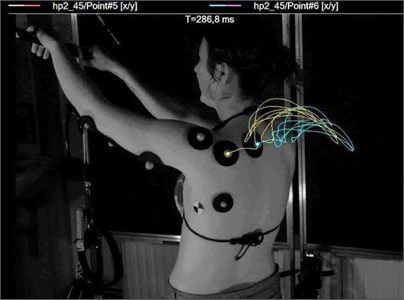
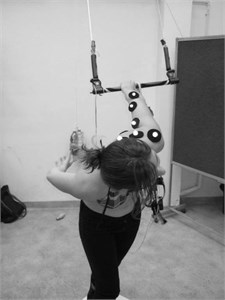
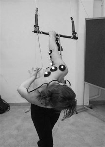
The authors reproduced in laboratory conditions the movement performed during putting the control bar, which is under load, behind the back. The vision-based technique of computing the trajectory of selected points on the kitesurfer’s body was conducted. These points were responsible the location of, respectively (Fig. 4): 1 – elbow appendix, 2 – further attachment of arm triceps muscle, 3 – closer attachment the lateral head of triceps muscle, 4 – base of humerus, 5 – the place of the trapezius muscle fiber intermediates, 6 – trailers trapezius muscle for teenagers squamous spine. The aim of the study was to record the work of individual muscle structures during take-off and handle pass maneuver with handling the control bar by a kitesurfer and to assess their repeatability employing a vision system based on high-speed cameras.
2. Description of the experiment
The measurement setup consisted of a control bar attached to the ceiling in order to retain the angle of deflection from the vertical line, observed while swimming. The load of the loose ends of the flying lines imitated the thrust of the kite during swimming on the tack.
Fig. 4View of the measurement setup and the markers location on the body of the surfer: a) experimental setup and markers placements over competitor’s body, b) vision-based measurements system: HSC – High Speed Cameras, HL – Halogen Lamps
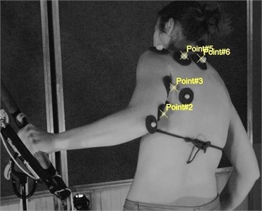
a)
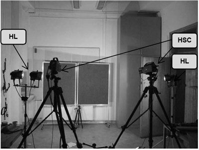
b)
In order to determine parameters needed to describe the competitor’s body motion (related to the activated groups of muscles) laboratory tests were conducted. Vision-based experimental setup (Fig. 4(b)) was composed of two Phantom v9.1 high speed camera with 2 MPix resolution (1632×1200 pixels) equipped with Carl Zeiss 35 mm lenses, a lighting system (set of halogen lamps) and TEMA Automotive motion analysis software. The software is equipped with tools to track markers and advanced post-processing tools. The developed vision system was calibrated (internally and externally) in compliance with procedures of Tema software.
Internal camera calibration was carried out by means of a calibration target in the form of the calibration planar board with chessboard pattern (Fig. 5). External camera calibration was performed using relative camera orientation procedure implemented in TEMA software. Internal and external camera calibration results are presented in Table 1 and Table 2 respectively. Lens distortion coefficients were estimated in TEMA’s planar target lens calibration procedure (Fig. 5). Distortion coefficients were necessary for the removal of optical distortions from the captured images before the measurement was carried out [7].
Generally, internal camera parameters are composed of focal length and principal point coordinates. Lens distortions estimated during camera calibration encompassed radial and tangential distortion coefficients (Table 1). External camera parameters deal with position and orientation between two cameras coordinate systems (Table 2, Fig. 6). For the purpose of the measurement noise estimation, standard deviations were calculated for 100 image sequences acquired by the stereo system. The mean value of measurement noise level was amounted to 0.067 mm.
Table 1Results of the internal camera calibration procedure
Left camera | Right camera |
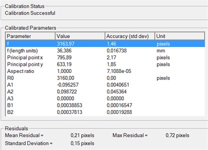 | 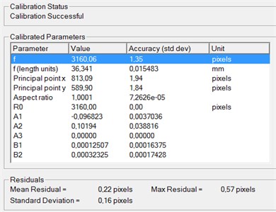 |
where: 1) the terms involving the coefficients: A – radial distortion, B – tangential distortion; 2) the terms related to residuals: Mean/Max Residuals – mean/ maximum difference between tracked points and reference model points | |
Table 2Results of the external camera calibration procedure and the reference coordinate system attached to the left camera
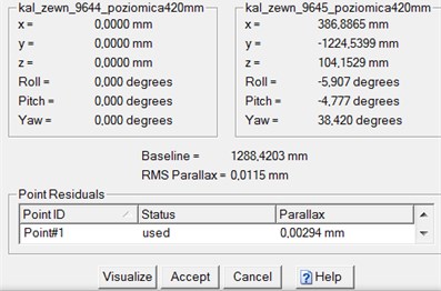 | 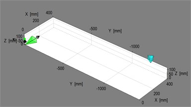 |
where: coordinates: , , position of the origin of the reference coordinate system of the right camera with respect to the left camera; Roll, Pitch, Roll – angels determined the orientation of the right camera coordinate frame with respect to the left one. | |
Fig. 5Planar calibration target
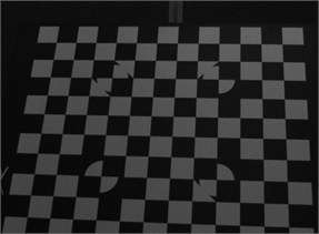
Fig. 6Exemplary setting of correlation method

Image sequences were acquired with the frequency of 300 Hz, with exposure time 500 ms and recording time 10.5 sec. Homemade ball-shaped markers were stuck on selected group of muscles of competitor body on the skin (Fig. 4(a)). These places corresponded to the activated group of muscles. The image correlation method was employed to track markers (Fig. 6). As a result of tracking process displacement and trajectory motion of characteristic kitesurfer’s points were investigated.
3. Results
As a result of multiple repetitions of the manoeuvre, functioning of individual muscle structures could be observed. The same change of distance between markers was notated each iteration of the maneuvers, which corresponded to the function of the observed muscles.
Fig. 7Repetitiveness of the movement trajectory obtained under laboratory conditions
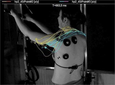
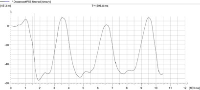
A visual analysis also allowed unequivocal determination of the moment of increased performance of the observed zones of muscles. Regularity and repetitiveness of the change of distance between the pointed heads of muscles prove that these muscle structures work more intensively while the surfer passes the handlebar behind his/her back. There are shown changes of distance between the two markers corresponding to the attachments of the triceps arm muscle during three muscular contractions caused by triple repetition of the maneuver of putting the control bar behind the back of the surfer in Fig. 7. The changes of distance between the heads of muscles (muscle flexibility) are individual and the distances hereby presented are not pathological. At every repetition of the maneuver a contraction of the forearm triceps muscle could be observed during the limb adduction phase as well as while straightening again the forearm holding the passed handlebar. In the very moment of passing the handlebar behind the back the load is being abruptly switched from one shoulder to another in a pathological shoulder position (the arm abducted, put over the sagittal plane of the body, the elbow put backward and abducted deep behind the surfer’s back together with the wrist). In the moment of passing the handlebar to the receiving hand and putting the shoulder again in a frontal position a group of muscles is involved, including the quadriceps with its deep muscles, the supraspinatus and infraspinatus as well as the deltoid muscles. This is undoubtedly the moment when most injuries occur.
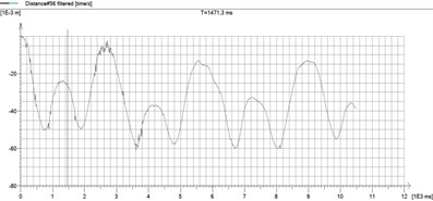
The averaged pick to pick value of displacement was about 30 mm. There are shown the change of distance between markers describing the observed head of the quadriceps during the same maneuver in Fig. 9. The averaged pick to pick value of displacement was about 14 mm. The shapes function presented in Fig. 8 and Fig. 9 of the displacement points are similar to the course of the periodic function, which testifies achieved good repeatability of measurement.
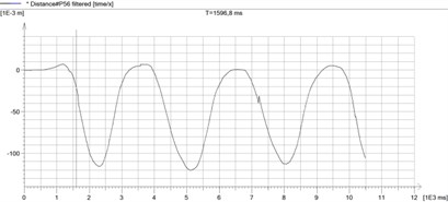
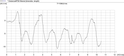
There are presented results of the change of distance between the two markers corresponding to the attachments of the triceps arm muscle for the next three measurement series and the rate of change of the length of the muscle in Fig. 10. The figures show that pick to pick value of every simple displacement at each repetition was between 27-28 mm. 14 measuring series were carried out, each contains a three-fold repeat of the full motion. The measurements were carried out one day, at the same load which reproduced optimal wind condition. Results for trapezius muscle fiber intermediates show in Fig. 11. The presented results recorded with respect to each of the three axes ( / time – left top, / time – right top, with / time – left down), and generated plot (right down).
Fig. 8The recorded repeatable change of distance between the points 2-3 (lateral head of the triceps of the forearm)
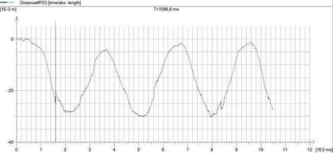
Fig. 9The recorded repeatable change of distance between the points 5-6 (trapezius muscle fiber intermediates) during three consecutive movements
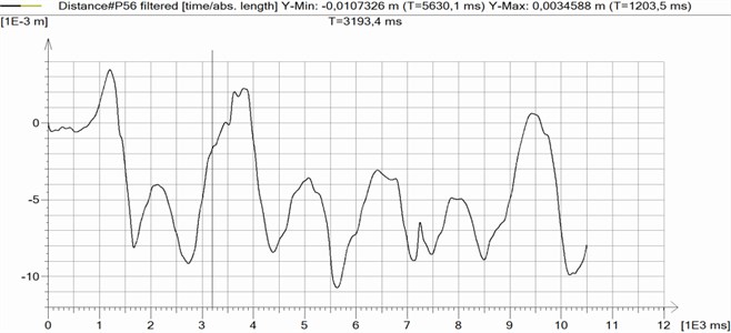
Fig. 10Change of distance between two markers for the three measurement series (1st- left top, 2nd – right top, 3th – left down) and change of velocity (1st series – right down)
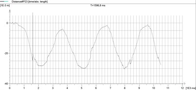
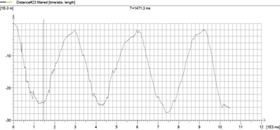
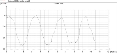
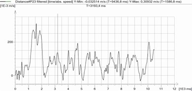
Fig. 11Results recorded with respect to each of the three axes (x / time – left top, y / time – right top, with / time – left down), and generated xyz plot (right down)
Depending on individual predispositions and the surfer’s skills, the angle of limb abduction during the handle pass trick might vary. The authors also analyzed the angle between the surfer’s back and his/her forearm (Fig. 12). However, it is an individual feature and a result of the surfer’s level of expertise, therefore a broader spectrum of subjects should be examined in order to draw reliable conclusions. Nevertheless, the surfers intuitively feel (through pain stimulus) which position is the most comfortable for them and it seems that the more they lean and the closer to the back they pass the handlebar from one hand to the other, the smaller the risk of injury is.
Fig. 12Attempt of passing the handlebar with the different angle of deviation between the arm and the back
There are presented attempts of passing the handlebar with the different angle of deviation between the arm and the back (and at the same time the spinal axis) in Fig. 12. Both the extent of surfer’s body inclination and the way of arm abduction have an impact on the way the shoulder structures (both muscles and ligaments) work. It is impossible to determine which position (which angle of deviation of the arm, inclination, rotation of the shoulder joint) is optimal if the analysis is carried out on a single subject. An analysis of the muscle work through EMG signal recording would give a wider picture (relation between the angle of deviation and the muscle contraction strength). Definite conclusions cannot be drawn because too few subjects have been analyzed.
4. Summary
Repeatable results reproducing the complex movement of a kitesurfer performing freestyle tricks were obtained by use of the presented post. In order to achieve high measurement resolution, the vision system architecture was developed and its configuration was arranged. In the literature, there are no reported uses of a vision system for measuring kitesurfer body to analyze the group of activated muscles [8-13]. For this reason, the measurement method presented in this paper can be regarded as a new approach for estimating kitesurfer body movements. Thanks to the developed vision system, by correlating the collected material describing the work force measurement of individual muscles by the use of EMG, the authors will propose a modification of the movement in order to change the angle of the force likely to endanger the correct work of muscles. Using the available models of the distribution of forces in the selected areas of the upper limb and creating their own models for an unusual position of the body during performing the described tricks, the authors will be able to pass the obtained knowledge to the coaches and therapists who care about the health of top kitesurfers.
References
-
Grzeczka A. Experimental modal analysis of kitesurf boards. 1st Conference – Achievements of Students’ Scientific Technical Universities, STUKNUT, 2015, (in Polish).
-
Grzeczka A. The theory and technique of sailing on kitesurfing. Conference on Technical and Scientific Issues in Competitive Sailing Sports, 2013, (in Polish).
-
http://Kiteschop.pl, 2016.
-
http://24surf.pl, 2016.
-
Sobotta – Atlas of Human Anatomy, Elsevier Urban and Partner. Wrocław 2012, (in Polish).
-
http://www.flickr.com, 2015.
-
Kohut P., Kurc K., Szybicki D., Cioch W., Burdzik R. Vision-based motion analysis and deflection measurement of a robot’s crawler unit. Journal of Vibroengineering, Vol. 1, Issue 8, 2015, p. 4112-4121.
-
Nebas T., Heller B. A smartphone based system for kite and board measurements in kitesurfing. The Conference of the International Sports Engineering Association, Procedia Engineering, Vol. 72, 2014, p. 477-482.
-
Lundgren L., Brorsson S., Osvalder A. L. Injuries related to kitesurfing. World Academy of Science, Engineering and Technology, Vol. 53, 2011, p. 1132-1136.
-
Lundgren L., Olandersson S., Hilliges M., Osvalder A. L. Biomechanics of extreme sports – a kite surfing scenario. 39th Nordic Ergonomic Society (NES) Conference, Lysekil, Sweden, 2007.
-
Valsecchi M., Saggin B., Tarabini M. Whole Body Vibration in Kitesurfing. Master’s Thesis, Milan, Italy, 2010.
-
Bourgois J. G., Boone J., Callewaert M., Tipton M. J., Tallir I. B. Biomechanical and physiological demands of kitesurfing and epidemiology of injury among kite surfers. Sports Med, Vol. 44, 2014, p. 55-66.
-
Grzeczka A., Kohut P., Kłaczyński M., Wittbrodt E., Uhl T. Vision-based motion analysis of a kite surfer. Vibroengineering Procedia, Vol. 6, 2015, p. 302-305.
About this article

This article was written under the substantive supervision of prof. Wittbrodt and prof. Uhl. Kitesurfing, as a field, motion analysis and selection of the manoeuvres causing most injuries – Anna Grzeczka. Piotr Kohut was responsible for vision-based measurement system and measurement methodology. Maciej Kłaczyński participated in the data analysis and data collection. Analysis of loads and the construction of experimental setup – Anna Grzeczka and Maciej Kłaczyński.
