Abstract
The aim of this study was to improve the reverse impact characteristics of large-flow pilot operated check valves, meanwhile reduce oscillation, cavitation and unloading time. Three different main poppets were selected, and the impact pressure and flow were set as 30 MPa and 1000 L/min, respectively. The cavitation phenomenon was explored based on the analysis of gas-liquid two-phase flow by Fluent software, and then experimental verification was performed. Meanwhile, the dynamic characteristics of pilot operated check valves were analyzed by the impact test system. The simulation results showed that the fluid pressure clearly decreased while flowing through the poppet area. The sudden decrease of flow area at the orifice port of the poppet resulted in an increase in flow-velocity, because the cavitation area appears on the side of the main poppet. A stepped throttling structure could effectively reduce the cavitation area, preventing the generation of cavitation. The experimental results showed that the pressure oscillation of a stepped main poppet significantly reduced during the process of unloading, at 28.41 MPa; with a flow gradient of 4.86×10⁵ L/min2; unloading time significantly reduced, for 711 ms; indicating it opened more rapidly and dynamic characteristics was superior. It can be concluded that the stepped throttling structure could effectively reduce the pressure oscillation of a pilot operated check valve during the process of unloading, improve response speed, enhance the impact properties, and reduce cavitation. This verified the correctness of the simulation and the rationality of the cavitation index.
1. Introduction
Compared with conventional mineral hydraulic oil, a water-based emulsion (a mixed emulsion typically composed approximately 95 % water and 5 % oil) has a large number of advantages, such as being environmentally-friendly, its low cost, the wide variety of sources, safety, and its low maintenance cost. It has been more widely used in food, fire control, high pressure cleaning, reactors, mining and other industries [1-3]. Thus, the water-based medium hydraulic transmission has become one of the new directions of development in the field of fluid power transmission and control [4-6]. For the water-based component, a large number of studies have been conducted [7-10]. The designed water-based hydraulic control valve has basically reached the pressure range of 1-32 MPa, and has entered the practical stage on the basis of theoretical research [11, 12]. Thus, the water-based emulsion pilot operated check valve is the main control component in the hydraulic system, and the application is quite extensive.
The operating mode of the pilot operated check valve is divided into two types of motion: forward and reverse directions. It acts as an ordinary check valve when operating in the forward direction. When operating in the reverse direction working, it is able to maintain the system pressure, and the work components can be unloaded through the opening. This requires good dynamic characteristics and a strong flow capacity.
However, at present, the rated working pressure in water-based hydraulic system is in excess of 30 MPa, and the flow rate is greater than 1000 L/min. The pilot operated check valve often works in a high-pressure state. In particular, when a pressure shock occurs, it generates a large impact flow caused by the external load. This leads to a serious cavitation [13-15] phenomenon, poor reliability and unstable dynamic characteristics. These problems seriously affect the safety and reliability of the pilot operated check valve and associated system.
Limited research has been conducted on impact characteristics and cavitation under the working condition of high-pressure large-impact [16], although a number of studies have been conducted on pilot-operated check valves [9, 11].
For these reasons, this study focused on main poppet design for large-flow water-based emulsion pilot operated check valves, and flow field cavitation simulation was conducted. Then, experimental verification was conducted using a high-pressure large-flow impact experimental system. Following this, the cavitation index was discussed, and the correctness of simulation and the rationality of cavitation index were verified.
2. The principle of pilot operated check valve
Fig. 1 is a structure diagram of a large-flow water-based emulsion pilot operated check valve. It consists of a valve body, main poppet, pilot poppet, valve sleeve, control piston, return spring, and other components. The main poppet and pilot poppet are pressed onto the seat by springs. The valve port of large-flow pilot operated check valve in this position is closed.
Fig. 1Structure of a large-flow pilot operated check valve: 1. Valve body, 2. Control piston, 3. Valve seat, 4. Control piston return spring, 5. Valve sleeve, 6. Poppet return spring, 7. Pilot poppet, 8. Main Poppet
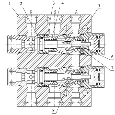
When the pilot operated check valve is in the unloading condition, the control ports will be passed by the controlling liquid, and control piston 2 moves to the right under the action of the controlling liquid. Firstly, pilot poppet 7 is opened. The high-pressure emulsion in the system overflows from the small gap between pilot poppet 7 and main poppet 8, so as to realize system pressure unloading. As the pilot poppet opens further, the system pressure decreases at a constantly and finally the secondary poppet 8 is opened by the control piston 2. A large amount of high-pressure emulsion overflows through the gap between the secondary poppet 8 and valve seat 3, so as to realize system flow unloading. The opening state of the poppets and the direction of flow are shown in Fig. 2.
As shown in Fig. 2(a), when the pilot poppet opens, the high-pressure emulsion in the system overflows from the small gap between pilot poppet and main poppet, so as to realize system pressure unloading. As shown in Fig. 2(b), when the main poppet opens, the emulsion overflows from the gap between the main poppet and the valve seat, so as to realize system flow unloading.
Fig. 2Valve poppet opening state
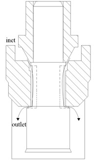
a) Pilot poppet opened
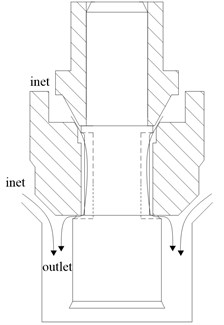
b) Main poppet opened
3. Structural design
In order to enhance the dynamic characteristics and reduce the cavitation, a multistage throttle structure is adopted, and three different kinds of main poppet are designed, as shown in Fig. 3. Type I is for a stepped three-step throttle structure, II for a stepped three-step throttle structure, and III for mutant type throttle structure. (In theory, the more the number of throttle structures, the more beneficial to reduce the vibration. However, in the practical application it is difficult to achieve this requirement.)
Fig. 3Different main poppets
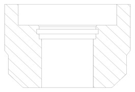
a) Main poppet I
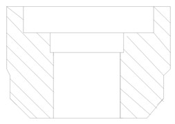
b) Main poppet II
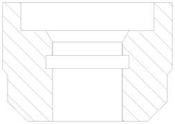
c) Main poppet III
4. Flow field simulations
4.1. Flow field model
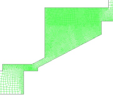
The grid generated by the ICEM software is generated using the unstructured grid mesh as the calculation domain, as shown in Fig. 4. In order to describe the process of cavitation, the following assumptions are made: the liquid-phase medium behaves as an incompressible fluid, the gas-phase medium behaves as a compressed fluid, the flow process is a constant temperature adiabatic process, the flow medium is an emulsion with a density of 1010 kg/m3, and the viscosity is that of water. The turbulence model is adopted a realizable - model. The flow field is initialized by the inlet pressure, the discretization equations set up by finite volume method, and pressure is coupled by first order up wind. The inlet boundary condition is set as the pressure-inlet, for 30 MPa; the outlet boundary condition is set as the pressure-outlet, for 5 MPa; the remaining boundaries are set as the wall; the reference pressure set to zero, and the wall condition as no slip. The work pressure of a large-flow pilot operated check valve is far greater than the force of gravity, thus the influence of gravity is ignored.
Fig. 4Grid model
4.2. Governing equation
The calculation of cavitation flow uses the Mixture model of Fluent software. Under this model assumption, the liquid and cavitation bubbles phases are coupled strongly and satisfy the local equilibrium condition within the scope of the smaller space length scale. Therefore, these phases can be approximated as a uniform fluid, which means that the following governing equations can be used:
1) Continuity equation. Mixture fluid phase:
Cavitation bubbles phase:
2) Momentum conservation equation:
3) Energy conservation equation:
where is the density of the mixed fluid; and the densities of the bubbles phase (emulsion vapor) and liquid phase (emulsion liquid), respectively; velocity vector for the mixed fluid; and the volume fractions for the bubbles and liquid phase, respectively; the generation rate for the emulsion vapor; the condensation rate for the emulsion vapor; the fluid static-pressure; and the energy for the bubbles phase and liquid phase, respectively; the temperature of the fluid; and the effective thermal conductivity.
In order to describe the process of cavitation, whereby the bubbles generating and breaking, and are derived by the Rayleigh-Plesset equation:
where is bubble radius; the pressure inside the bubble; the viscosity; and the surface tension.
4.3. Grid independence analysis
The numerical simulations are conducted on three different grid sizes. Results of the pilot poppet opened completely are shown in Table 1. Increasing the grid number over 18000 does not result in a significant change in pressure and velocity. Thus, the 18000 grid should be selected for the numerical simulation.
Table 1Grid independence analysis
Grid numbers | Maximum pressure /Pa | Minimum pressure /Pa | Maximum velocity /(m/s) | Minimum velocity /(m/s) |
10000 | 30006322 | 3540 | 205.4122 | 0 |
18000 | 29998766 | 3539.99 | 195.515 | 10.29 |
37000 | 29998850 | 3539.99 | 198.615 | 10.45 |
4.4. Gas-liquid two phase flow simulation
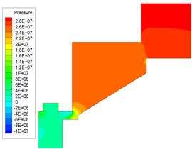
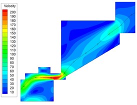
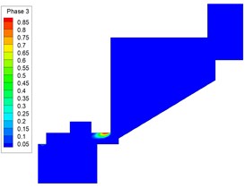
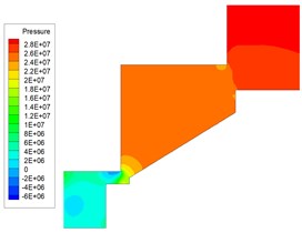
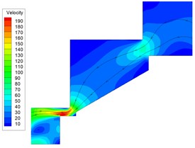
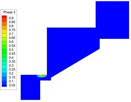
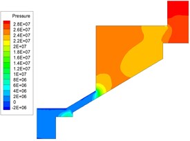
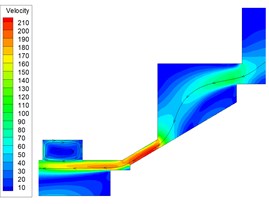
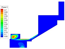
The cavitation simulation results of main poppet I, II and III are shown in Fig. 5, 6, and 7, respectively.
As shown in Fig. 5 for the main poppet I, the fluid pressure is 21 MPa before throttling, and after throttling the pressure at the head of the pilot poppet is 15 MPa, which then gradually decreases. The cavitation region is small and is located near the corner side of the main poppet. A larger flow-velocity appears in the center of the throttling zone. The volume of gas phase increases significantly at the corner of the throttling outlet.
Fig. 5Two-phase flow simulated result for main poppet I
a) Pressure nepho
b) Velocity vector
c) Gas phase volume fraction
Fig. 6Two-phase flow simulated result for main poppet II
a) Pressure nephogram
b) Velocity vector
c) Gas phase volume fraction
As shown in Fig. 6 for the main poppet II, the fluid pressure is 19 MPa before throttling, and after throttling the pressure at the head of pilot poppet is 10 MPa. As can be seen from the gas-liquid phase volume fraction, the cavitation region appears near the corner side of the main poppet, similar to that of the main poppet I, which has a limited effect on the overall flow channel.
As shown in Fig. 7 for the main poppet III, the fluid pressure is 15 MPa before throttling, and after entering throttling the pressure is in an approximate range of 0-1 MPa. As can be seen from the gas phase volume, cavitation occurs alongside the main poppet near the sealing surface.
On comparison of the simulation results of Fig. 5, Fig. 6 and Fig. 7, it can be seen that the cavitation area of the stepped multistage throttling structure is minimal, and it is located away from the sealing pair. The cavitation region of the mutant type throttle structure (main poppet III) is relatively larger. Thus, from the viewpoint of reducing cavitation, the stepped multistage throttling structure is preferable. This is mainly because the stepped throttling structure allows the pressure difference to be distributed across the throttle orifices, which reduces the pressure difference of a single throttle orifice, thus reducing the generation of cavitation.
Fig. 7Two-phase flow simulated result for main poppet III
a) Pressure nephogram
b) Velocity vector
c) Gas phase volume fraction
5. Experimental and discussions
5.1. Experimental method
The hydraulic schematic diagram of an accumulator pressurized cylinder experimental system is shown in Fig. 8.
Firstly, the right of the pressurized cylinder fills with emulsion through the emulsion pump station, pushing the pressurized cylinder piston to the left. Secondly, the accumulator charging reaches the preset pressure through the oil pump station. Then, the pilot valve opens the cartridge valve, the emulsion in the accumulator is rapidly released, and a high pressure forms in the right of the pressurized cylinder. Finally, through emulsion pump station to open the tested-valve.
Fig. 8Principle diagram of experimental system: 1. Oil source, 2. Check valve, 3. Accumulator, 4. Cartridge valves, 5. Pilot valve, 6. Pressure cylinder, 7. Pressure sensor, 8. Displacement sensors, 9. Tested valves, 10. Emulsions pump station, 11. Reversing valve
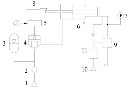
After completion of the accumulator impact, the loading process ends. The values of the pressure and displacement sensors are recorded. Thus, the flow of the tested check valve is:
where is the rodless cavity area of the pressurized cylinder. Then, the pressure, and flow versus time curves are obtained.
5.2. Impact characteristics
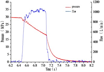
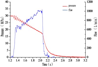
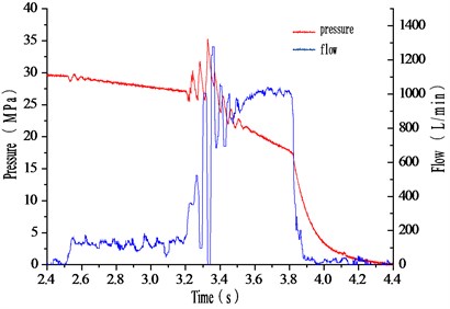
Experimental research was conducted on the influence of the main poppet on the impact characteristics. The impact and control pressure are set at 30 MPa and 14 MPa, respectively, and the impact characteristics curves for different main poppets are as shown in Fig. 9. The timing starts from the point where the pressure begins to decline. The unloading time is that from when the flow started rising to when it dropped to zero.
Flow gradient = peak flow in rapid rising phase /time.
Fig. 9Impact characteristics curves for different main poppets
a) Main poppet I
b) Main poppet II
c) Main poppet III
From the aspect of pressure, the effect of main poppet I, with the lower fluctuation peak and shorter time, has an advantage over that of main poppets II and III. From the aspect of flow, the influence of the difference in the main poppets is significantly higher than that for pressure. The dynamic characteristics testing data of the different main poppets are shown in Table 2.
According to Table 2 and Fig. 9, under impact conditions, the unloading time of main poppet I is the shortest, the flow gradient is the highest, and the pressure oscillation peak is the smallest. Because the flows of main poppets II and III are always in the stage of rising or oscillating without a stable range, their flow gradients can be ignored.
Table 2Dynamic characteristics testing data of different main poppets
No. | Peak pressure /MPa | Peak flow / (L/min) | Flow gradient / (105 L/min2) | Unloading time / ms |
Poppet I | 28.41 | 1078 | 4.86 | 711 |
Poppet II | 30.03 | 1019 | 898 | |
Poppet III | 35.29 | 1277 | 1454 |
It can be concluded that, in terms of impact characteristics, the stepped multistage throttling structure is better than that the mutant type structure. Multistage throttle structures could result in a rapid flow-velocity decline, and a pressure rise, however, the mutant type multistage throttling structure results in a flow-velocity rebound after decline, which leads to drastic oscillation. The stepped structure is characterized by a gradual decrease across the whole flow channel, so the change of flow and pressure are smooth and stable, and thus there will be no drastic oscillation.
5.3. Cavitation characteristics verification
The generation of cavitation is closely associated with the inlet pressure, and the occurrence of cavitation will be accompanied by a change in energy and power. Thus, the cavitation characteristics of a pilot operated check valve could be investigated through the impact pressure power spectrum:
where is the autocorrelation function defined in the mathematical expectation; and the power spectral density of function . However, the energy changes of the whole phase need to be investigated by the cavitation index:
where is the frequency of the impact pressure; the power spectrum values corresponding to frequency. According to Eq. (8), the cavitation index could be calculated as shown in Table 3.
Table 3Cavitation index of different main poppets
No. | Poppet I | Poppet II | Poppet III |
9285000 | 8503272.14 | 9898928.57 |
As can be seen from Table 3, the cavitation index of main poppet III is the largest, which means that is has the highest degree of cavitation, followed by main poppet I. Visibly, the cavitation index is not directly associated with all the parameters of the impact characteristics, but is identical to that of the flow field simulation, This verifies the validity of the simulation, and also illustrates that adopting the cavitation index of impact pressure to illustrate the degree of cavitation is reasonable.
6. Conclusions
This study designed the main poppets for a high-pressure, large-flow emulsion pilot operated check valve, and then conducted a cavitation simulation. On this basis, the experimental verification was carried out by the impact test system. It is concluded that this is the optimal structure in these three structures. The simulation results showed that the stepped throttling structure could effectively reduce the cavitation area, preventing the generation of cavitation. The experimental results showed that the impact characteristics of the stepped main poppet throttling structure is optimum during the process of unloading. However, it has less pressure oscillations, faster unloading time, superior dynamic characteristics, and a lower cavitation index. This indicates that the stepped throttling structure could effectively reduce the pressure oscillation of pilot operated check valves during the process of unloading, as well as improve the response speed, enhance the impact properties, and reduce the cavitation. This demonstrated that the stepped main poppet throttling structure is an optimal result, which is consistent with the simulation results that verified the correctness of the simulation and the rationality of the cavitation index.
References
-
Scheffcls G. Developments in Water Hydraulics. Hydraulics and Pneumatics, Vol. 12, 1996, p. 33-34.
-
Koskinen K. T., Vilenius M. J. Water hydraulics-a versatile technology. Journal of the Japan Hydraulics and Pneumatics Society, Vol. 29, Issue 7, 1998, p. 13-19.
-
Suzuki K., Akazawa S., Nakao Y. Development of cam-drive type proportional valve for water hydraulics. International Journal of Automation Technology, Vol. 6, Issue 4, 2012, p. 450-456.
-
Suzuki K., Urata E. Development of a direct pressure-sensing water hydraulic relief valve. International Journal of Fluid Power, Vol. 9, Issue 2, 2008, p. 5-13.
-
Suzuki K., Urata E. Development of a water hydraulic pressure-compensated flow control valve. International Journal of Fluid Power, Vol. 9, Issue 3, 2008, p. 25-33.
-
Park S. H., Kitagawa A., Kawashima M. Water hydraulic high-speed solenoid valve. Part 1: development and static behaviour. Proceedings of the Institution of Mechanical Engineers. Part 1: Journal of Systems and Control Engineering, Vol. 218, Issue 5, 2004, p. 399-409.
-
Liu Lei, Zhang Desheng, Zhao Jiyun Design and research for the water low-pressure large-flow pilot-operated solenoid valve. Strojniski Vestnik – Journal of Mechanical Engineering, Vol. 60, Issue 10, 2014, p. 665-674.
-
Majdic F., Velkavrh I., Kalin M. Improving the performance of a proportional 4/3 water-hydraulic valve by using a diamond-like-carbon coating. Wear, Vol. 297, Issues 1-2, 2013, p. 1016-1024.
-
He Zhi-kai Simulation Analysis of Prop Pilot Operated Check Valve and Research on Visualization of Flow Field. Taiyuan University of Technology, 2012.
-
Majdic F., Pezdirnik J., Kalin M. Experimental validation of the lifetime performance of a proportional 4/3 hydraulic valve operating in water. Tribology International, Vol. 44, Issue 12, 2011, p. 2013-2021.
-
Wang Hui, Li Ji-yang Fluid-solid coupling analysis of large flow hydraulic controlled check valve on hydraulic support. Journal of Liaoning Technical University (Natural Science), 2014, p. 623-626.
-
Tang Bing, Lu Kun, Hao Yan-wen, et al. Numerical simulation of flow field in hydraulic cone valve for water medium. Journal of Lanzhou University of Technology, Vol. 33, Issue 4, 2007, p. 54-58.
-
Ou Guo Fu, Rao Jie, Zhang Li-te, et al. Numerical investigation of cavitation erosion/solid particle erosion in high differential pressure control valves in coal liquefaction. Tribology, Vol. 33, Issue 2, 2013, p. 155-161.
-
Ji Hong, Fu Xin, Yang Hua-yong The research on the effects of runner shape for overflow valve cavitation noise. Chinese Journal of Mechanical Engineering, Vol. 38, Issue 8, 2002, p. 19-22.
-
Liu Y. S., Huang Y., Li Z. Y. Experimental investigation of flow and cavitation characteristics of a two-step throttle in water hydraulic valves. Proceedings of the Institution of Mechanical Engineers, Part A: Journal of Power and Energy, Vol. 216, Issue 1, 2002, p. 105-111.
-
Yi D., Lu L., Zou J., et al. Interactions between poppet vibration and cavitation in relief valve. Proceedings of IMechE Part C: Journal of Mechanical Engineering Science, Vol. 229, Issue 8, 2015, p. 1447-1461.
Cited by
About this article
This work is supported by Specialized Research Fund for the Doctoral Program of Higher Education (20130095110012), Postgraduate Research Innovation Plan Project in Jiangsu Province (KYLX_1378) and the Priority Academic Program Development of Jiangsu Higher Education Institutions (PAPD).
