Abstract
In this study, an innovative adaptive variable camber compliant wing, with skin that can change thickness and tailing edge morphing mechanism that is designed based on a new kind of artificial muscles, is designed. Consisted of a compliant base plate and seamless and continuous compliant skin with the artificial muscles embedded in, this trailing edge morphing mechanism is extremely light in weight and efficient in reconfiguration of the wing sectional profile. To demonstrate the feasibility of this design, a simulative experiment of this kind of artificial muscles was designed and carried out. A demonstrative wing section with simulative driving skin mechanism and the compliant skin was manufactured. The demonstration wing section shows that the trailing edge morphing mechanism designed and simulative driving skin work good, with a –30°/+30° trailing edge morphing achieved. Targeting this innovative design, an airfoil design approach, employing CST parametric methodology, XFOIL and Multi-Objective Particle Swarm (MOPS) optimizer, is developed for the preliminary design of this innovative wing. A new selector is introduced to facilitate the searching process and improve the robustness of this method. The results show that this method is capable of designing airfoils for this special wing in a quick and effective way.
1. Introduction
Morphing wing technologies have been widely studied recently due to the demands for safe, affordable and environmental compatible aircrafts. Power consumption, noise emission and overall aircraft environmental impact can be significantly reduced with enhanced flight performance by morphing technologies. In addition, morphing wing technologies were also proved to be useful in increasing the critical flutter velocities [1, 2] and improving wing aeroelastic efficiency [3].
Several morphing concepts, such as Mission Adaptive Wing in 1980s [4], Smart Wing Program in 1990s [5], Mission Adaptive Compliant Wing in 2000s [6] and a very recent Variable Camber Compliant Wing (VCCW) concept by the Air Force Research Laboratory (AFRL) [7, 8], have been proposed. Other advantages of morphing wing technologies have also been verified by wind tunnel tests and flight tests in the above programs and other researchers’ work.
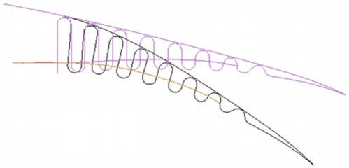
Yokozeki et al. [9] developed a variable geometry morphing airfoil using corrugated structures to actuate a flexible seamless flap by a wire system in the leading part of the structure, through comparison between experimental results of morphing trailing edge and that of a hinged wing, showing great potential in the improvement of lift coefficient (Seen in Fig. 1(b)). By introducing variable torsion, through rotate ribs around a fixed aluminum rod, to a wing made of carbon fiber skin (except for the trailing edge) that is stiff in torsional direction, Vos et al. [10] developed a warp controlled wing twist without relying on extremely powerful actuators. This wing demonstrates that sufficient control of the rolling motion of aircraft and maximization of the lift-to-drag ratio can be achieved through active wing twist. Superior aerodynamic performance of seamless skin variable camber wing due to morphing leading edge and trailing edge and span wise wing twist has been demonstrated by Joo et al.’s VCCW concept through wind tunnel testing (seen in Fig. 1(a)) [7, 8].
Fig. 1a) The VCCW concept and the corrugated structure design
a)
b)
It can be easily discovered through the more recent studies above that the newly proposed morphing mechanisms are generally consisted of seamless and continuous skin made of carbon fiber or composite material and actuators that drive the deformation of the skins. Though those wings are lighter in weight compared with the hinged morphing mechanisms that made of aluminum or steel to retain structure strength due to stress concentration, the whole morphing structures are still too “heavy” in the weight of skin and driving mechanisms for a compliant wing aircraft, especially for high altitude long endurance UAVs that may operate for days even months (such as solar-powered UAVs by Google and Facebook for providing free Wi-Fi access). However, development in the field of artificial muscle may provide some visionary solutions to this problem [11-13].
Artificial muscles, especially the Pneumatic Artificial Muscles (PAMs), are not new in aerospace applications. Many studies on application of artificial muscles in aerospace, such as driving flaps or driving morphing mechanisms, has been carried out [14, 15]. However, these designs suffer some performance, scalability and cost problems due to the restrictions of the artificial muscles. Such as the application of electro-thermally driven shape-memory metal, which can provide fast contraction and large strokes, is restricted by the expense and its hysteretic feature that makes it difficult to control. Polymeric electric field–driven electro-strictive rubbers and relaxor ferroelectrics are attractive because of their large strokes and high efficiencies but would be difficult to deploy as muscle-like fibers because of the high required electric fields.
However, very recently, Carter et al. [11] developed a new kind of fast, scalable, non-hysteretic, long-lift tensile muscles made of fishing line and sewing thread. A contraction of 49 %, lift loads over 100 times heavier than can human muscle of the same length and weight, and 5.3 kilowatts of mechanical work per kilogram of muscle weight, which is similar to that produced by a jet engine, have been demonstrated. Experimental results show that this kind of muscles can hold a weight of 0.91 to 295 kg, which is totally sufficient enough to drive a morphing mechanism of a variable camber compliant wing. The tensile actuation of this kind of artificial muscles by thermal control is shown in the following Fig. 2.
Fig. 2Thermal contraction of the artificial muscles
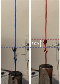
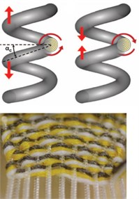
Fig. 3Conceptual design of the adaptive variable camber compliant wing
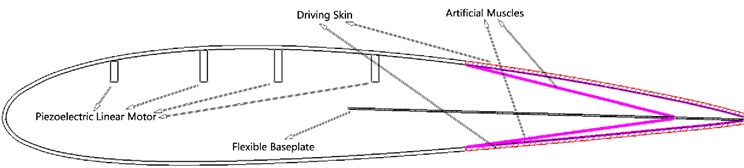
In this study, based on this new kind of artificial muscles, a new concept named Driving Skin, which integrates driving mechanism made of artificial muscles with compliant skin to provide actuation force for morphing mechanism so as to reduce overall weight of the whole wing and enhance aerodynamic force resistance of morphing part, is proposed. An innovative wing with this driving skin and compliant skin that can change wing thickness is designed. Consisted of a compliant base plate, seamless and continuous compliant driving skin, this trailing edge morphing mechanism (hereinafter refers to as driving skin mechanism) is extremely light in weight and efficient in reconfiguration of the wing profile. The conceptual design is shown in Fig. 3. To demonstrate the feasibility of this design, a simulative experiment of this kind of artificial muscles was designed and carried out. A demonstrative wing section with simulative driving skin mechanism and the compliant skin was fabricated shown in Fig. 4. Not like the span twist around a rod that results in different angle-of-attack of the airfoil profiles along the wing span in other studies, this wing is capable of achieving roll control and gust load alleviation to optimize cruise and maneuver conditions by different thickness distribution and trailing edge morphing.
As this variable camber compliant wing can adapt to current flight conditions by changing thickness and the driving skin mechanism, the airfoil may vary under different flight conditions according to different requirements. Therefore, aerodynamic performance of numerous airfoils under specific flight conditions needs to be investigated in the preliminary design. While currently there is no such a method for this new wing, a new airfoil design method that employs CST parametric methodology, XFOIL and Multi-Objective Particle Swarm (MOPS) optimizer, is developed for the preliminary design of this innovative wing. A new selector is introduced to facilitate the searching process and improve the robustness of this method.
Fig. 4Fabricated demonstration wing section
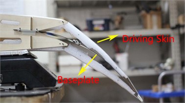
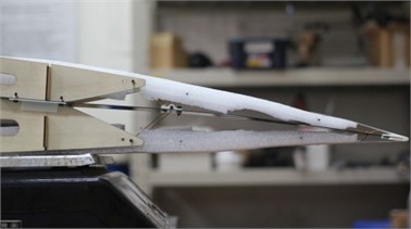
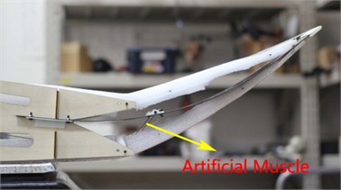
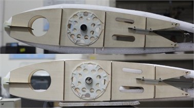
In the Fig. 4, the demonstration wing section that simulates the function of artificial muscles and driving skin is presented. Ropes are used and drew by the white 3D-printed disc that rotates around a carbon hollow tube, to simulate the contraction, thus the function of artificial muscles. The white foams that contains ropes inside are used to simulate driving skin, for both deformation and bearing aerodynamic force. As for this demonstration wing section, the drawing ropes will deform the baseplate, simulating the function of artificial muscles, to achieve trailing edge morphing as shown in the pictures. The detailed design will be explained in other paper and here only gives a simple illustration as it is not the primary concern in this paper.
2. Method development
Inspired by the urgent demand of aerodynamic performance of numerous airfoils in the preliminary design of variable camber compliant wing, this quick airfoil design method that takes into account a cambering trailing edge and changing airfoil thickness is capable of fast giving airfoils with optimum performance at both design point and off-design points.
2.1. Airfoil description
One of the most important things in design and optimization of an airfoil is the parameterization of airfoil, which determines not only the accuracy of airfoil description but also the speed. There are many ways in the parametric description of the airfoil geometry, such as free from deformation (FFD) method based on NURBS spline curve, Bezier Curve method, etc. M. Kulfan and E. Bussoletti [16, 17] proposed a “shape function” and a “class function” to describe the geometry of an airfoil, in which the “shape function” provides the ability to directly control key geometry parameters such as leading edge radius, trailing edge boat tail angel and closure to a specified aft thickness, while the “class function” generalizes the method for a wide variety of geometries; the “shape function” and “class function” methodology, which is also called the Class-Shape-Transformation (CST)methodology, can describe a 2D airfoil with a handful of control points. Lane et al. [18] pointed out that, compared to Bezier curves, the CST methodology describes airfoil with less parameters due to appropriate class functions that are similar to airfoil profiles. Guan et al. [19] studied the description accuracy of several methodologies such as Bezier Curve method, Hicks-Henne method and PARSEC, finding that the CST methodology is featured with less control parameters and higher accuracy, which is the reason that it is chosen in this study. In the CST methodology, the “class function” is used to define the basic geometry of an airfoil, from it all geometries optimized are derived; the “shape function” is used to modify the basic geometry to obtain needed geometry. In this study, as XFOIL was used to investigate the aerodynamic performance of optimized airfoils, the chord of airfoil investigated is set to be 1. For both upper and lower surfaces, the airfoil with chord of 1 can be stated as:
where, is the “class function” that defines an airfoil with round nose and sharp trailing edge, in which is for providing a round nose and is required to ensure a sharp trailing edge; is the thickness of trailing edge, and is used to control the trailing edge thickness; is the “shape function”, representing a general function that describes the middle section shape of airfoil.
Usually, Bernstein Polynomial is used as basic function of the “shape function” to describe an airfoil, because it needs less parameter in describing airfoil compared with Bezier Curve method and other methods. The Bernstein polynomial of order () can be defined as:
where, the coefficients factors are binominal coefficients defined as:
Thus, an airfoil that uses Bernstein Polynomial of order n to describe can be stated as:
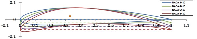
The order n in the Bernstein Polynomial determines the accuracy of the description, but it does not say the higher the better. It was discovered that a Bernstein Polynomial of order 5 is sufficient to describe the airfoil NACA2410 accurately, while Bernstein Polynomial of order larger than 12 starts to compromise accuracy of the description. To reduce computational cost and keep the basic shape of the airfoil from being greatly changed, in which case the improvement of aerodynamic performance is resulted by change of angle of attack rather than the optimized airfoil itself, middle points of the control points of both upper and lower surfaces were used as control points instead, which halve the number of control points and hence reduce much computational cost. The parametric geometry of NACA2410 with Bernstein Polynomial of order 5 and the control points are shown in Fig. 5.
Fig. 5Comparison between original geometry and parametric geometry of NACA2410
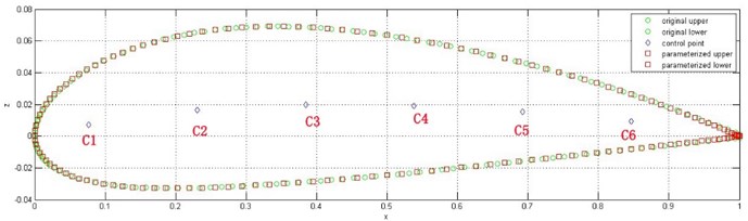
In the Fig. 5, the green dote line is the original geometry and the red dote line is the parametric geometry; the blue diamond-shaped dots in the middle are control points to be used in airfoil design. The parametric geometry shows a very good accuracy in the description of the original airfoil. To simulate the morphing process, only the 1st, 5th and 6th control points (defined as C1, C5, C6) in the Fig. 3 were used in the design process. When reviewing factors that affect the endurance of aircraft, the relative thickness, leading edge (controlled by C1), trailing edge (controlled by C5 and C6) and trailing edge thickness of airfoil should be taken into consideration, thus, relative thickness coefficient for controlling thickness at corresponding control points, trailing edge thickness and position of trailing edge of upper surface were also taken in to account as parameters. Therefore, in the design, the geometry of the whole optimized airfoil is a function of C1, C5, C6, , and . As the endurance parameter is determined by the geometry of airfoil, the function of can be presented as:
From Eq. (5) we can see that, taking endurance of aircraft as objective, only 6 parameters are needed for the airfoil design, which may significantly reduce computation cost. The reason why the thicknesses at corresponding control points were not manipulated individually lays to the fact that by doing so the computational cost will be dramatically increased, while the aerodynamic performance of design airfoils shows no commensurate improvement. Compared with other airfoil design or optimization methods that take hours, even days and weeks, this method only take about 60 minutes to obtain a satisfactory result.
In the demonstrative design stated later in this paper, the leading edge morphing is restrained as wind tunnel testing shows that XFOIL is unable to accurately estimate the morphing leading edge part [7]. To achieve a subtler control of both leading edge and trailing edge, Bernstein Polynomial of larger order may be applicable in the design, which will not be discussed in this paper.
2.2. Selection of solver and optimizer
As development of this method is driven by the needs of airfoils for a variable camber compliant wing for low speed high altitude long endurance application, XFOIL was chosen as the solver to evaluate the aerodynamic performance of optimized airfoils because of its fast calculation and accuracy for low speed applications [20].
Multi-Objective Particle Swarm optimization (MOPS)was chosen as optimizer in the airfoil design, it mimics the social behavior of animal groups such as flocks of birds or fish shoals. The process of finding an optimal design point is likened to the food-foraging activity of these organisms. Particle swarm optimization is a population-based search procedure where individuals (called particles) continuously change position (called state) within the search area. In other words, these particles “fly” around in the design space looking for the best position. The detailed explanation of this optimizer is shown in the reference [21].
Compared to the genetic algorithm adopted by many other researchers in airfoil design or optimization, the MOPS optimizer showed a much better performance in both searching speed and final output for optimum objectives in this method, which may provide some inspiration for other to use it in their research.
2.3. Introduction of a new selector
During the design process, as the optimizer changes variable parameters for thousands or even tens of thousand times to find an optimum result, a large number of deformed airfoils, for which XFOIL is unable to calculate or fails to converge at some of the off-design points, may be generated, resulting in a larger computation cost and poor off-design performance of the airfoil.
In the investigation, it was discovered that there were many airfoils generated with very good values at design point but poor geometry and poor off-design point performance, which means solely taking design objective as selector will compromise the robustness of the airfoil obtained. Therefore, in addition to the objective, as which maximum endurance parameter was taken in this investigation, optimizer should be “informed” what is a good airfoil, to help it identify acceptable airfoils.
To solve this problem and improve the robustness of this method, a new selector is introduced. It was found in the investigation that airfoils generated with good geometry and good off-design performance are prone to achieve convergence in XFOIL, therefore, after the new airfoil is generated, performance estimation through XFOIL will be carried out at many design points, such as at different angle-of-attacks, different Mach numbers or different Reynolds numbers. Then, MATLAB codes will automatically obtain the number of design points that has been converged and compare it with total number of design points, the ratio of number of converged design points to total number of design points (hereinafter refers to the Convergence Ratio) will be taken as a performance robustness indicator of the airfoil, making it a very good objective and selector for the optimizer. As it can be seen, the convergence ratio ranges from 0 to 1; 0 represents totally unacceptable airfoil, which will consume a very large portion of computation time, while 1 represents airfoil a very good airfoil that will be quickly evaluated by XFOIL; the larger the ratio is, the better performance robustness the airfoil will have. In this investigation, 61 design points in total were evaluated, with a convergence ratio of 1 was taken as objective and 0.90 as lower limit. This selector has shown great improvement in the selection of airfoils with robust off-design performance.
As for this method, endurance parameter, lift coefficient, drag coefficient, lift-to-drag ratio, maximum lift coefficient and momentum coefficient can be taken as both objectives and constraints at different Mach numbers, different Reynolds numbers and given lift coefficients. Control parameters of baseline airfoil can be automatically calculated and output. After input the control parameters into the optimizer and set the upper and lower limits of control parameters as well as objectives and constraints, the codes will automatically perform the searching process and output the best result at the end of search. This method can be possibly used to optimize natural laminar flow (NLF) airfoils and identify the transition location, which will not be discussed in this paper but may be studied in future research as it is not of a great concern right now.
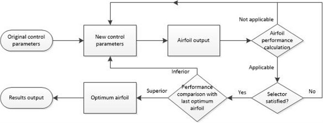
The Fig. 6 shows the procedure of airfoil design. For each iteration after the original airfoil, the control parameters listed in Eq. (5) will be changed and correspondingly a new airfoil will be obtained. The performance of the new airfoil will be calculated at and off design point, totally 61 cases, with results output automatically. If the Convergence Ratio is larger than 0.9 in this iteration, the endurance parameter of the new airfoil will be compared with that of last optimum airfoil. If the new one is superior in the comparison, then the old one will hence be replaced by the new one. At the end of the iteration, the most optimum airfoil will be taken as final result.
Fig. 6Procedure of preliminary design of airfoils
3. Airfoil design and discussion
Before manufacturing, the internal structure and external profile of beams and ribs should be determined. To do so, the airfoil profiles at all operation conditions should be known to decide the minimum thickness of external profile, the internal structure can then be determined. Therefore, preliminary airfoil design determines not only the aerodynamic performance, but also the overall structure of the variable camber compliant wing.
3.1. Design objective
The original purpose of this study was to develop a wing for high altitude long endurance UAV, so the airfoil for cruise flight conditions was taken as primary target. Many efforts have been put into this work by other researchers, most of them taking lift-to-drag (L/D) ratio as objective in their airfoil design or optimization efforts. But in this study another objective was taken as follows.
When reviewing the laws of flight physics, for battery powered UAVs with fixed weight, it is clear that the power required for constant level flight depends on flight velocity and drag force :
As a function of flight velocity, air density (a function of flight altitude), area of the wing planform , and the coefficient of drag , the drag force of aircraft can be stated as:
The minimum flight velocity is a strong requirement to ensure the minimum lift force for maintaining flight altitude. As a function of air density, flight velocity, coefficient of lift and area of the wing planform, the lift force of aircraft can be stated as:
where, is the weight of aircraft and is the acceleration due to gravity. Since the lift force must be equal to the gravity force of aircraft in cruise flight, the flight velocity of aircraft in cruise flight can be deduced:
Inserting Eq. (8) and Eq. (6) into Eq. (5) yields the power required for cruise flight of aircraft:
As limited by payload of aircraft, the battery or fuel of propeller-driven long endurance aircraft is strictly limited in weight. Assuming that the energy output of aircraft by batteries or fuel for cruise flight is a constant value of , the endurance of an aircraft in cruise flight can be deduced:
where, , , and are fixed values for a certain aircraft in cruise flight, the , which is called endurance parameter , offers the best aircraft endurance, and it was taken as design objective in this investigation. Increasing the endurance parameter improves endurance of the aircraft, though in most times the maximum occur at the same design point with the lift-to-drag ratio, sometimes it is not, and so is a more accurate indicator of aircrafts’ endurance.
3.2. Airfoil designed for cruise flight
In this study, the lift coefficient was taken as for the high altitude long endurance application, noting that the airfoils designed in this study is only for a uniform wing, and the wing twist and thickness distribution were not taken into account, which needs to be further studied in the future.
Usually, normal long endurance aircrafts are optimized for operating at one flight state due to the fact that a wing with fixed profile achieves optimum aerodynamic performance under certain conditions. However, this wing can operate at multiple flight states by changing the profile of the wing, so airfoils for three cruise flight states, assuming the in cruise flight operates at , were designed in this study to determine the basic profile. The flight conditions, objectives and constraints taken in this study are shown in the following.
Flight conditions: , and (1) 1×10⁶; (2) 1.5×10⁶; (3) 2×10⁶.
Objectives: : maximize; convergence ratio: 1.
Constraints: convergence ratio 0.95.
The airfoils designed and their aerodynamic performances are shown in the following figures, noting that the airfoils preliminarily designed take no consideration of structure and weight issues.
Fig. 7Airfoils designed at cl=1.2 and Ma=0.15 under different Reynolds numbers
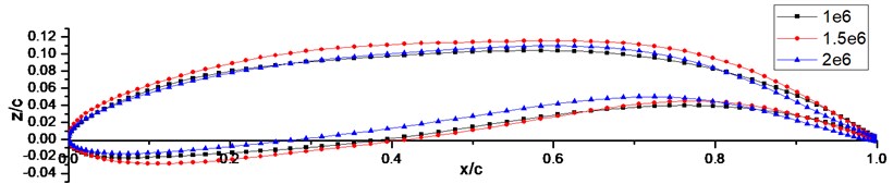
From the Fig. 7 we can see that the trailing edges start to bend at approximately 75 % of chord, cambering the airfoil to provide better aerodynamic performances. From Fig. 3 we know that in the design process the trailing edge was freed at about 70 % of chord according to C5 stated above, so an initial bending at approximately 60 % of chord was expectable. However, the three airfoils all start to bend at 75 % of chord and tell us that this a better option for increasing endurance parameter, which is also supported by an investigation stated in Fig. 8, verifying this method’s effectiveness in designing airfoil. Through this preliminary design, the thickness distribution and internal structure of the adaptive variable camber compliant wing can be preliminary determined.
3.3. Aerodynamic performance of the airfoils and discussion
As the main objective of this preliminary airfoil design is to find an airfoil with superior performance that satisfies structural requirements for internal mechanisms, namely the thickness distribution along the chord line, the aerodynamic performance of the obtained 2-D airfoils were only numerically studied at this stage. More complex aerodynamic performance study of 3-D wings, numerically or experimentally, may be carried out in future study.
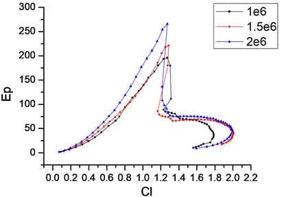
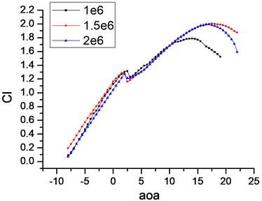
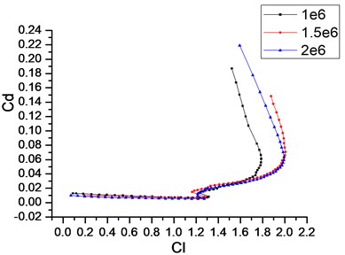
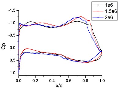
Fig. 8Aerodynamic performance of the three airfoils designed
a)
b)
c)
d)
The above figures show the basic aerodynamic performance of the three airfoils. From Fig. 8(a) we can see that, the maximum endurance parameters of the three airfoils designed all occur at approximately , which is exactly the operating condition specified in the design process, then the endurance parameters come into a sharp decrease, indicating that the airfoils designed are the optimum when operate at this given condition. From Fig. 8(b) we can see that in addition to a maximum endurance parameter at design point, the three airfoils all have very good off-design performance in lift coefficient and post stall, with two of them have up to approximately 2, showing a good resistance to changing flight conditions and good post stall performance even without changing profile. The Fig. 8(c) shows that even lift coefficients of the three airfoils continue to increase after a small drop at , the drag coefficients begin to increase significantly, and that is the reason why the endurance parameters encounter a sharp decrease. The pressure coefficient distribution in Fig. 8(d) shows that the airflow velocities at the lower surface decrease slowly and then increase at the trailing edge part. The pressure of airfoils at upper surface maintains at the leading half part, slowly drops due to acceleration of airflow velocity, and then encounters a sharp increase at approximately 85 % of chord, which is due to the transition of airflow from laminar flow to turbulent flow. It means that the airfoils designed have laminar flows attached on more than 80 % of the upper surface at operation conditions, which is a phenomenon seen in natural laminar flow (NLF) airfoils. The pressure differentiation between upper surface and lower surface also indicates that the higher lift performance of the airfoil designed is mainly due to the cambered trailing edge, which also demonstrates that the variable camber compliant wing has great potential in aviation application for long endurance, because larger lift coefficient can also mean smaller wet surface of aircraft of certain weight, thus parasite drag can be reduced.
3.4. Further application of the method
The performance of the three airfoils designed above shows not only the aerodynamic gaining of the adaptive variable camber wing, which adapts itself according to different flight conditions to achieve optimum performance, but also the effectiveness of this airfoil design method. From Fig. 6 we can see that the airfoils start to morph at about 75 % of chord, another investigation was carried out to demonstrate that this bending is in compliance with optimum performance requirement rather than constraints of control points.
Under same constraints on the control points and thickness ratio, another airfoil that also took endurance parameter as objective but without specifying lift coefficient was designed. The airfoil designed operates at 0.15 and 1.5×10⁶, and its shape and aerodynamic performance (refers to as free in the figures), together with that of the airfoil above (refers to as 1.2) and baseline airfoil NACA2410, is show in Fig. 8 and Fig. 9, all operate at the same flight conditions.
Fig. 9Airfoils design at Cl=1.2 and free of lift constraint
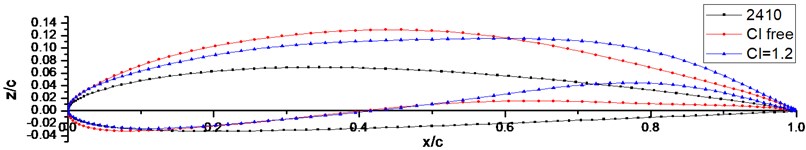
Fig. 10Aerodynamic performance comparison of the three airfoils
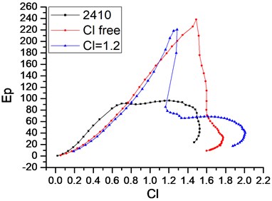
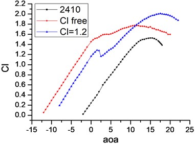
From Figs. 9-10 we can clearly see that the airfoil designed without giving specific lift coefficient starts to bend at approximately 55 % of chord, which is in compliance with the expectation; and its higher maximum endurance parameter occurs at approximately 1.5. Both airfoils designed have much better aerodynamic performance compared with the baseline airfoil. This study demonstrates that this method is capable of designing airfoils with optimum performance operates at specific given flight conditions, which is very helpful in the preliminary airfoil design of an adaptive variable camber compliant wing aircraft.
In application of this method, it was found that the method is very convenient and efficient for airfoil design and optimization of not only variable camber compliant wing aircraft, but other aircrafts with fixed profiles. A subtler control of trailing edge or leading edge morphing is achievable by increasing the order of Bernstein Polynomial, but it is strongly recommended that the order should not exceed 12. Increasing order of Bernstein Polynomial to gain a more accurate control of airfoil profile should take into consideration the performance compliant skin and driving skin developed in changing the profile.
4. Conclusions
In this study, an adaptive variable camber compliant wing, which can change thickness and morph trailing edge with driving mechanism made of a new kind of artificial muscles embedded in skin, is designed. A demonstration wing section that simulates the effect of this design was fabricated, which shows a very good performance. Targeting this innovative wing, a preliminary airfoil design method is developed. Employing CST parametric methodology, XFOIL and Multi-Objective Particle Swarm (MOPS) optimizer, this method is effective and efficient in designing airfoils for the adaptive variable camber compliant wing, showing a promising application prospect.
References
-
Courchesne S., Popov A. V., Botez R. M. New aeroelastic studies for a morphing wing. Proceedings of the 48th AIAA Aerospace Sciences Meeting Including the New Horizons Forum and Aerospace Exposition, Washington, DC, 2010.
-
Grigorie T. L., Popov A. V., Botez R. M., et al. Controller and aeroelasticity analysis for a morphing wing. AIAA Atmospheric Flight Mechanics (AFM) Conference, 2011.
-
Sabri F., Meguid S., Lakis A. Modeling flutter response of a flexible morphing wing for UAV. 53rd AIAA/ASME/ASCE/AHS/ASC Structures, Structural Dynamics and Materials Conference, 20th AIAA/ASME/AHS Adaptive Structures Conference 14th, 2012.
-
Decamp R., Hardy R. Mission adaptive wing advanced research concepts. 11th Atmospheric Flight Mechanics Conference, 1984.
-
Kudva J., Appa K., Martin C. A., et al. Design, fabrication, and testing of the DARPA/Wright Lab smart wing wind tunnel model. Proceedings of the AIAA 38th Structures and Structural Dynamics Conference, Kissimmee, Florida, 1997.
-
Hetrick J. A., Osborn R. F., Kota S., et al. Flight testing of mission adaptive compliant wing. 48th AIAA/ASME/ASCE/AHS/ASC Structures, Structural Dynamics, and Materials Conference, Structures, Structural Dynamics, and Materials and Co-located Conferences, 2007.
-
Marks C. R., Zientarski L., Culler A., et al. Variable camber compliant wing-wind tunnel testing. 23rd AIAA/ASME/AHS Adaptive Structures Conference, 2015.
-
Joo J. J., Marks C. R., Zientarski L., et al. Variable camber compliant wing-design. 23rd AIAA/ASME/AHS Adaptive Structures Conference, 2015.
-
Yokozeki T., Sugiura A., Hirano Y. Development and wind tunnel test of variable camber morphing wing. 22nd AIAA/ASME/AHS Adaptive Structures Conference, 2014.
-
Vos R., Gurdal Z., Abdalla M. Mechanism for warp-controlled twist of a morphing wing. Journal of Aircraft, Vol. 47, Issue 2, 2010, p. 450-457.
-
Haines C. S., Lima M. D., Li N., et al. Artificial muscles from fishing line and sewing thread. Science, Vol. 343, Issue 6173, 2014, p. 868-872.
-
Ware T. H., McConney M. E., Wie J. J., et al. Voxelated liquid crystal elastomers. Science, Vol. 347, Issue 6225, 2015, p. 982-984.
-
Chen P., Xu Y., He S., et al. Hierarchically arranged helical fibre actuators driven by solvents and vapours. Nature Nanotechnology, Vol. 10, 2015, p. 1077-1083.
-
Yerkes N. T., Wereley N. M. Pneumatic artificial muscle activation for trailing edge flaps. 46th AIAA Aerospace Sciences Meeting, Reno, NV, 2008.
-
Woods B. K. S., Bubert E., Kothera C. S., et al. Design and testing of a biologically inspired pneumatic trailing edge flap system. AIAA Structures, Structural Dynamics, and Materials Conference, Schaumberg, IL, 2008.
-
Kulfan B. M., Bussoletti J. E. Fundamental parametric geometry representations for aircraft component shapes. 11th AIAA/ISSMO Multidisciplinary Analysis and Optimization Conference, 2006.
-
Kulfan B. M. Universal parametric geometry representation method. Journal of Aircraft, Vol. 45, Issue 1, 2008, p. 142-158.
-
Lane K. A., Marshall D. D. A surface parameterization method for airfoil optimization and high lift 2D geometries utilizing the CST methodology. AIAA Paper, Vol. 1461, 2009, p. 5-8.
-
Guan X., Li Z., Song B. A study on CST aerodynamic shape parameterization method. Acta Aeronautica et Astronautica Sinica, Vol. 33, Issue 4, 2012, p. 625-633.
-
Drela M., Youngren H. XFOIL 6.9 User Primer. http://web.mit.edu/drela/Public/web/xfoil_doc.txt, 2001.
-
Nakamura M., Izui K., Nishiwaki S., et al. A multi-objective particle swarm optimization incorporating design sensitivities. Proceedings of the 11th AIAA/ISSMO Multidisciplinary Analysis and Optimization Conference, Virginia, 2006.
Cited by
About this article

