Abstract
Ball screw feeding system has wide application in machine tools, and its dynamic research is very important. The drive screw can be seen as a rotating Timoshenko beam under the pre-tension force. Considering the bearing stiffness, the boundary condition of the screw is spring supported. Also, considering the contact deformation between the screw and the worktable and the worktable moving, the screw is added an intermediate moving spring-mass system. Using boundary conditions and continuity conditions, the lateral and longitudinal frequency equations of the screw feeding system are derived considering the effect of gyroscope, the pre-tension force, the bearing stiffness, the contact between the worktable and the screw and the moving of the worktable. The effect of the system parameters on the natural frequency is studied. The diameter, the pre-tension force, the bearing stiffness, the contact stiffness and the rotational speed of the screw have effect on the vibration frequency and the frequency varies when the worktable moves along the screw from the left to the right end. This work supplies a base for designing the drive system to avoid resonance and to improve the stability of the system.
1. Introduction
Ball screw feeding system has wide application in machine tools. With increasing of the feeding velocity and machining precision, the vibration of the feeding system becomes more and more important, and gets attention from researchers.
Yang et al. [1] structured the dynamic model of screw-workbench system based on the Tinoshenko beam theory account of lateral shear of beam. Feng et al. [2] analyzed the modal and dynamic response of the feeding screw using Ansys. Li et al. [3] used FEA method to do the modal analysis and studied the un-damped free vibration of the leading screw, and got the intrinsic frequency and the vibration model. Jun [4] analyzed ball screw feeding system’s static and dynamic characteristic of a CNC lathe, and got the natural frequency and vibration mode of the feeding system. Dong et al. [5] presented a method to model and design servo controllers for flexible ball screw drives with dynamic variations and proposed a mathematical model describing the structural flexibility of the ball screw drive containing time-varying uncertainties and disturbances with unknown bounds. Feng et al. [6] examined the relationship between the ball screw preload variation and detected vibration signals. Wang et al. [7] took the form of a hollow screw shaft structure containing multiple tuned mass dampers to achieve the lateral multi-mode vibration control of the screw shaft, considering the time-varying vibration characteristics of the ball screw caused by the continuous movement of the nut.
In the screw drive system, the screw is slender, and it can be seen as Timoshenko beam. The worktable moves with the screw rotation, and its mass is much larger than the screw, so the worktable can be seen as a moving mass. Considering contact stiffness between the worktable and the screw, the screw drive system is a rotating beam with moving spring-mass system. Tang et al. [8] derived exact frequency equations of the Timoshenko beam for various boundary conditions. Arboleda-Monsalvea et al. [9] analyzed the stability and free vibration of a Timoshenko beam-column with generalized end conditions subjected to constant axial load, and used intermediate flexural connection to model the crack of the beam. You et al. [10] analyzed natural frequencies, modes and critical speeds of axially moving beams on different supports based on Timoshenko model, and derived the governing differential equation of motion from Newton’s second law. Azama et al. [11] analyzed the dynamic responses of a Timoshenko beam subjected to a moving mass and a moving sprung mass, also derived governing differential equations for beam vibration. Dehestani et al. [12] presented an analytical-numerical method to determine the dynamic response of beams carrying a moving mass, and investigated the influences regarding the speed of the moving mass on the dynamic response of beams. Ghayesh et al. [13] investigated the nonlinear forced vibrations and stability of an axially moving Timoshenko beam with an intra-span spring-support. Lin [14] utilized the numerical assembly method (NAM) to determine the exact natural frequencies and mode shapes of the multi-span Timoshenko beam carrying a number of various concentrated elements including point masses, rotary inertias, linear springs, rotational springs and spring-mass systems. Lee et al. [15] analyzed the dynamic contact problem of a tensioned beam with clamped-pinned ends when the beam contacts a moving mass-spring system, derived the dynamic contact equations using constraints and equations of motion for the beam and moving mass and then discretized using the finite element method. The above research focused on the lateral vibration, but also the longitudinal vibration existed. Cortés et al. [16] studied the longitudinal vibration behaviour of a damped rod.
Zhang et al. [17-20] also studied the vibration and dynamic response of the screw feeding system in consideration of the bearing stiffness, the contact deformation of the feeding system, but neglected the moving of the worktable. In present work, the frequency equation of the screw feeding system under elastically supported is derived, considering the effect of gyroscope, the pre-tension force, the bearing stiffness, the contact stiffness of the system and the intermediate moving spring-mass. Effects of the system parameters on the screw’s lateral and longitudinal frequency are discussed.
2. Lateral vibration frequency equation of the screw feeding system
Using separation of variables, the lateral vibration displacement of the beam can be written as:
From the Ref. [20], considering the shear deformation, rotary inertia and the pretention force, the mode shape of the Timoshenko beam can be expressed as:
where:
If is an imaginary, and replace and , respectively.
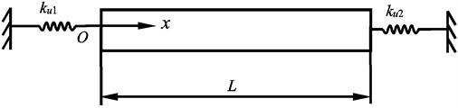
The dynamic modal of the screw feeding system is shown in Fig. 1. To consider the contact deformation, the bearings at both ends of the screw are expressed by spring stiffness coefficients. The worktable and the screw connect at point . The contact deformation between the screw and the worktable is also expressed as spring stiffness coefficients, so an intermediate spring-mass system of the screw is added. And also, the contact deformation between the worktable and the guide way is considered using spring stiffness coefficients.
Fig. 1The dynamic model of the screw feeding system lateral vibration
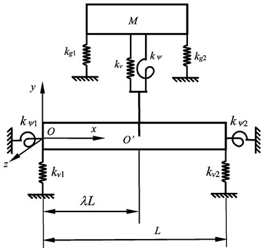
The screw and the worktable contact at the point and the distance between the contact point and the left end of the screw is . So, the screw is made of two segments. The lateral vibration mode shape of the screw can be written as:
where - are coefficients of the lateral vibration mode shape yet to be determined.
The bearings at both ends of the screw are expressed by spring’s stiffness, so the screw is spring supported at both ends, and the boundary conditions of the lateral vibration are:
The screw continues at contact point , and the compatibility conditions at point can be expressed as:
where “–” expresses the left side of the contact point , and “+” expresses the right side of the contact point .
The vibration of the worktable includes the vibration in direction and rotation around the axis, which equations are:
Letting:
Substituting Eqs. (1), (3), (8) and (9) into Eqs. (4-7), these equations can be arranged as:
For the non-trivial solution, the coefficient matrix must be singular, so the frequency equation is:
3. The longitudinal vibration frequency equation of the screw feeding system
From Ref. [21], the longitudinal vibration displacement of the rod is written as:
The longitudinal vibration mode shape of the rod is expressed as:
where .
Fig. 2The dynamic model of the screw feeding system longitudinal vibration
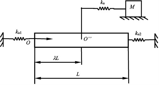
The longitudinal vibration dynamic model of the screw feeding system is shown in Fig. 2. Considering the bearing’s stiffness, the screw is spring supported at the both ends. Considering the contact deformation between the ball screw and the moving worktable, the screw is added with an intermediate moving spring-mass system. The distance between the contact point and the left end of the screw is . The longitudinal vibration mode shape of the screw is:
where - represent four integration constants yet to be determined.
Both ends of the screw subject to elastic supports, so the boundary conditions of the screw are:
The screw continues at the contact point , and the compatibility conditions are:
According to the Newton’s second law, the vibration equation of the worktable is:
Setting:
By putting Eqs. (12), (14), (18) into the Eqs. (15-17), equations about - and can be got, and written as:
For non-trivial solution, the coefficient matrix must be singular and one can get longitudinal frequency equation:
4. Calculation and analysis
4.1. Lateral vibration frequency
4.1.1. The lateral vibration frequency of the beam without intermediate spring-mass system
If the worktable and the contact deformation between the worktable and the screw are not considered, the screw can be seen as Timoshenko beam, which supporting modal is shown in Fig. 3.
From Ref. [21], the first order lateral frequency of the classic Euler- Bernoulli beam under simply supported at both ends is:
If is the first order natural frequency of the Euler-Bernoulli beam under freely supported at both ends, and is the first order natural frequency of the Euler-Bernoulli beam under clamed supported at both ends, the expression of both are:
Fig. 3The supporting model of the beam lateral vibration
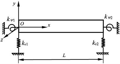
If the lateral stiffness of bearing is enough large but the rotation stiffness around axis is zero, the beam can be seen as simply supported; If the lateral stiffness and rotational stiffness of the bearing are close to zero, beam can be seen as freely supported; If the lateral stiffness and rotational stiffness of the bearing are both enough large, the beam can be clamped supported. Letting 0, 0, 0, 0, 0, Eq. (11) reduces to 4×4 orders. Letting 2.07×10¹¹ Pa, 8.3×10¹⁰ Pa, 7.85×10³ kg·m-3, 1000 mm, 10 mm, 20 mm, 40 mm respectively, the lateral vibration frequency is calculated. Letting 1000 N·μm-1, the frequency is written as when the frequency is written as when 1000 N·μm-1, 1000×106 N·rad-1, the frequency is written as . The comparison between the result from Eq. (11) and Euler- Bernoulli beam is listed in Table 1.
Table 1The frequency comparison between the Euler- Bernoulli beam and Timoshenko beam
10 mm | 1.2670×10² | 2.8722×10² | 1.2669×10² | 2.1872×10² | 2.8710×10² |
20 mm | 2.5341×10² | 5.7444×10² | 2.5329×10² | 4.3714×10² | 5.7329×10² |
40 mm | 5.0682×10² | 1.1489×10³ | 5.0569×10² | 8.7186×10² | 1.1355×10³ |
From Table 1, one can see that , and calculated from this paper, are close to the vibration frequency of the Euler-Bernoulli beam under simply, freely and clamed supported at both ends, respectively. But the vibration frequency of Timoshenko beam is slightly lower than that of the Euler-Bernoulli beam, moreover the larger the diameter is, the greater the influence of rotary inertia and shear deformation is, and the greater the difference between the both is.
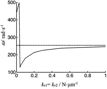
The lateral vibration frequency of beam is calculated as a function of the radial supporting stiffness of the bearing which is shown in Fig. 4. From Fig. 4 one can see that the frequency varies when the radial supporting stiffness of the bearing increases. When and tend to infinity, the frequency is close to that under the simply supported.
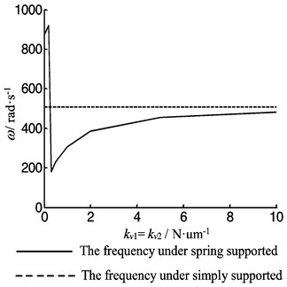
Letting 1000 N·μm-1, Fig. 5 is the first order lateral vibration frequency as function of the rotational stiffness of the bearing when 10 mm, 20 mm, 40 mm respectively. The frequency increases with an increasing of the beam’s diameter due to the inertia. When 0, the frequency is close to that under simply supported and with rotational stiffness gradually increasing, the lateral vibration frequency increases to that under clamed supported ( and are listed in Table 1).
Fig. 4The first order lateral frequency of the beam as function of the radial stiffness of the both bearing
a)10 mm
b)20 mm
c)40 mm
Fig. 5The first order frequency of the beam as a function of the rotational stiffness of the both bearing
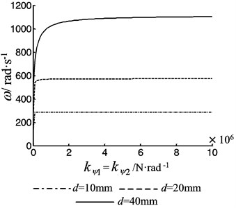
Fig. 6The first order frequency of the beam as function of the pretention force
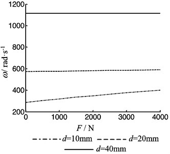
Fig. 6 is the first order lateral vibration frequency as function of the pre-tension force . The vibration frequency increases with an increasing of the pre-tension force due to the increasing of the lateral stiffness. The smaller the diameter of the screw is the lager the effect of the pre-tension force is.
Fig. 7 is the first order lateral vibration frequency as function of the rotational speed of the beam. One can see that the vibration frequency increases with an increasing of rotational speed due to the gyroscopic effect. So, the lager the diameter of the screw is the lager the effect of rotational speed is.
4.1.2. The lateral vibration frequency of the screw feeding system with intermediate spring-mass system
The lateral vibration of the screw feeding system is simulated by Ansys. The element type of the screw and the worktable are Beam188 and Mass21 respectively, and the contact stiffness of the lead screw and the worktable is neglected, and the boundary condition at the two ends is clamped. In Eq. (11), the stiffness of the bearing and the contact stiffness between the worktable and the screw are all 200 N·μm-1. When the worktable is at different position, the calculation results of Ansys are compared with the results of this paper written in Table 2. Because the stiffness of Ansys model is larger, the frequency of the system increases.
Table 2The lateral vibration frequency comparison of the system between Ansys and this paper
Ansys | 1394 | 1633 | 1394 |
Eq. (11) | 1162 | 1418 | 1162 |
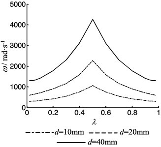
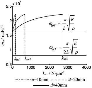
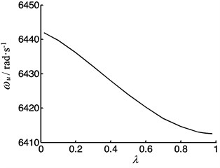
Assuming the intermediate supporting stiffness of the screw 200 N·μm-1, 200×106 N·rad-1, the bearings’ stiffness 200 N·μm-1, 200×106 N·rad-1, when the worktable moves along the screw, the lateral vibration frequencies of the screw feeding system are shown in Fig. 8 according Eq. (11). From Fig. 8, one can see that the vibration frequency of the system increases as its diameter increases, and the frequency varies when the worktable moves. When the worktable moves along the screw from the left end to the right end, the frequency is symmetrical about the midpoint of the screw. When the worktable is at middle of the screw, the lateral frequency is biggest. The vibration frequencies of the system with different bearings’ stiffness are shown in Fig. 9. When the two bearings’ stiffness are not same, the frequency is not symmetrical, and the larger the diameter of the screw is, the more obvious asymmetry of the frequency is.
Fig. 7The first order frequency of the beam as function of the rotational speed
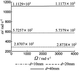
Fig. 8The vibration frequency of the feeding systems a function of position coefficient of the worktable
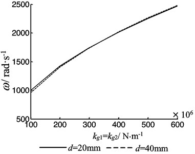
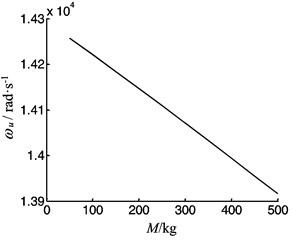
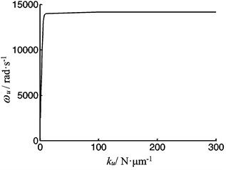
Letting 0.5, Fig. 10 shows the vibration frequency of the system depends on intermediate stiffness. From Fig. 10, one can see that when the intermediate stiffness increases, the frequency increases. Fig. 11 shows that the frequency of the system depends on the mass of the worktable, and Fig. 12 shows the frequency of the system depends on the contact stiffness between the worktable and the guide way. One can see that the frequency decreases with the mass increasing, and increases with the contact stiffness increasing between the worktable and the guide way.
Fig. 9The vibration frequency of the feeding system as a function of the bearings stiffness
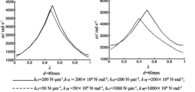
Fig. 10The vibration frequency of the feeding system as function of the intermediate support stiffness
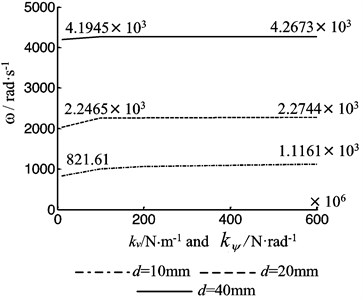
Fig. 11The vibration frequency of the feeding system as function of the worktable mass
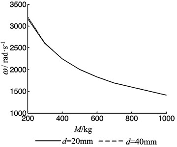
Fig. 12The vibration frequency of the feeding system as function of contact stiffness between the worktable and the guide way
4.2. The longitudinal vibration frequency
4.2.1. The longitudinal vibration frequency of the rod without the intermediate spring-mass system
Without considering the worktable, the longitudinal vibration of the screw system can be simplified as a rod with spring supported which is shown in Fig. 13. The bearing’s supporting of the rod’s both ends can be simplified as two kinds, one is clamped when the bearing’s axial stiffness is big enough, and the other is free when the bearing’s axial stiffness is small enough.
When the supporting of rod’s both ends is clamed or free, the longitudinal vibration frequency equation all are:
Fig. 13The longitudinal vibration supporting model of the rod
In this paper, letting 0, 0, Eq. (20) reduces to 2×2 orders, which is the longitudinal frequency equation of the rod under spring supported at both ends. Letting 2.07×10¹¹ Pa, 8.3×10¹⁰ Pa, 7.85×10³ kg·m-3, 1000 mm, the frequency of longitudinal vibration is calculated. Letting the bearing’s supporting stiffness of the screw both ends is same, and the diameter 10 mm, 20 mm, 40 mm respectively, the first order longitudinal vibration frequency with the axial supporting stiffness of both ends bearings is shown in Fig. 14. When bearing stiffness of both ends is 0, the vibration frequency is under freely supported at both ends. With the increasing of bearing stiffness, longitudinal vibration frequency of the rod increases first, but fells sharply at a certain critical stiffness , and then gradually increases to reach the natural frequency under clamed supported at both ends. Fig. 14 shows that the bearing supporting can be simplified as freely supported at both ends if the bearing stiffness is smaller than the critical stiffness , and can be simplified as clamed supported at both ends if the bearing stiffness is more than the critical stiffness . The critical stiffness of is related to the diameter of the rod and increases with the rod diameter increasing. The bearing supporting stiffness on both ends should be reasonable according to the diameter of the rod to avoid the vibration instability.
Fig. 14The vibration frequency of the rod as function of the both bearing stiffness
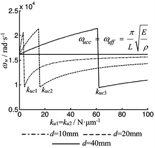
Fig. 15The vibration frequency of the rod as function of the bearing stiffness when ku2= 0
When the rod’ length or the temperature variety is larger, it is often used to be under clamed supported at one end and freely supported at the other end, in which the vibration frequency equation is:
Letting 0, the vibration frequency with the axial supporting stiffness of one end bearings is calculated from this paper shown in Fig. 15. When 0, the vibration frequency is under freely supported of both ends. With the increasing of the vibration frequency increases gradually, and fells sharply to the frequency under clamed supported at one end at a critical stiffness . From Fig. 15, one can see that if the screw is under freely supported at one end, only when the other end supporting stiffness is greater than the critical stiffness , it can be seen as clamed supporting.
From Eqs. (23-24) one can see that, if the stiffness of the bearing is not considered, the longitudinal vibration frequency of the rod does not change with the diameter of the screw. But from Fig. 14-15 one can see that, if considering the stiffness of the bearing, the frequency of the longitudinal vibration of the rod varies with the diameter.
4.2.2. The longitudinal vibration frequency of the screw feeding system with the intermediate spring-mass system
Using Ansys to simulate the longitudinal vibration of the screw feeding system, the element types of the screw and the worktable are Link180 and Mass21 respectively, and the contact stiffness of the screw and the worktable is neglected, and the boundary condition at the two ends is clamped. According Eq. (20), the stiffness of the bearing is 1000 N·μm-1, and the contact stiffness between the screw and the worktable is 300 N·μm-1. The calculation results of ANSYS and this paper are shown in Table 3.
Table 3The longitudinal vibration frequency comparison of the system between Ansys and this paper
Ansys | 1.2526×10⁴ | 1.2466×10⁴ | 1.2526×10⁴ |
Eq. (20) | 1.4207×10⁴ | 1.4147×10⁴ | 1.4207×10⁴ |
Considering the worktable moving and the contact deformation between the worktable and the screw, the longitudinal vibration frequency is calculated according the Eq. (20). Letting 1000 N·μm-1> , the frequency depends on the position coefficient is shown in Fig. 16. The frequency varies when the worktable moves along the screw. When the worktable moves along the screw from the left end to the right end, the frequency is symmetrical about the midpoint of the screw. When the worktable is at the middle of the screw, the frequency is lowest.
Fig. 16The vibration frequency of the feeding system as a function of position coefficient of the worktable under clamed-clamed supported
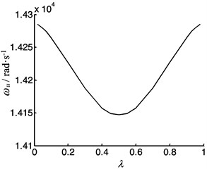
a)20 mm
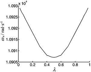
b)40 mm
If the screw is long or the temperature varies large, the screw is often under clamed-freely supported. So, letting 3000 N·μm-1 and 0, the frequency depends on the position coefficient is shown in Fig. 17. The vibration frequency decreases when the worktable moves along the screw from the left end to the right end.
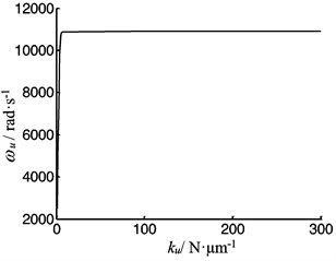
Fig. 18 shows that the longitudinal vibration frequency of the system depends on the mass of the worktable, and the frequency decreases with the mass increasing. Fig. 19 shows the frequency of the system depends on the contact stiffness between the worktable and the screw. The frequency increases with the contact stiffness increasing, but when the contact stiffness is large enough, the frequency almost remains unchanged with the contact stiffness increasing.
Fig. 17The vibration frequency of the screw feeding system as a function of position coefficient of the worktable under clamed-free supported
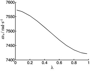
a)20 mm
b)40 mm
Fig. 18The vibration frequency as function of the worktable mass
a)20 mm

b)40 mm
Fig. 19The vibration frequency as function of the contact stiffness between the screw and the worktable
a)20 mm
b)40 mm
5. Conclusions
Through the above analysis, the following conclusions are obtained:
1) The diameter, the pre-tension force and the rotational speed have effect on the lateral vibration frequency of the beam, and when the diameter, the pre-tension force or the rotating speed increases, the frequency increases.
2) The lateral vibration frequency varies when the worktable moves along the screw from the left end to the right end, and the frequency is biggest when the worktable is at the middle of the screw. If the bearings stiffness of the both ends is same, the frequency is symmetrical about the midpoint of the screw; and if the bearings stiffness is not same, the frequency is not symmetrical. The larger the diameter of the screw is, the more obvious asymmetry of the frequency is.
3) The longitudinal vibration frequency of the rod varies with the bearings stiffness, and there is a critical stiffness . The critical stiffness is related to the diameter of the rod and increases with the rod diameter increasing. The bearing supporting stiffness of both ends should be reasonable in order to avoid the vibration instability.
4) The longitudinal frequency of the screw feeding system varies when the worktable moves along the screw. When the screw is under clamed-clamed supported, the frequency is symmetrical about the midpoint of the screw. When the worktable is at the middle of the screw, the frequency is lowest. But when the screw is under clamed-freely supported, the longitudinal vibration frequency decreases when the worktable moves along the screw from the left end to the right end.
5) The mass of the worktable and the contact stiffness of the system have effect on the longitudinal frequency of the system. The frequency decreases with mass of the worktable increasing and increases with the contact stiffness increasing.
References
-
Yang Yong, Zhang Weimin, Zhao Hongpu Dynamic characteristics of ball screw system. Journal of Vibration Measurement and Diagnosis, Vol. 33, Issue 4, 2013, p. 664-772, (in Chinese).
-
Feng Shuli, Li Duanneng, Niu Jinlei, Zhou Xinyun Analysis of vibration and scheme of vibration reducing and acceleration for long-span ball screw. Machine Tool and Hydraulics, Vol. 42, Issue 17, 2014, p. 61-64, (in Chinese).
-
Li Fangfang, Jia Ping, Ning Huaiming Modal analysis of a certain type screw based on ANSYS software. Machinery Design and Manufacture, Vol. 11, 2010, p. 61-62, (in Chinese).
-
Jun Wan Analysis of Static and Dynamic Characteristic of Ball Screw Feeding System based on ANSYS. Journal of Mechanical Transmission, Vol. 34, Issue 5, 2010, p. 68-70, (in Chinese).
-
Dong Liang, Tang Wen Cheng Adaptive back stepping sliding mode control of flexible ball screw drives with time-varying parametric uncertainties and disturbances. ISA Transactions, Vol. 53, 2014, p. 110-116.
-
Feng Guohua, Pan Yilu Investigation of ball screw preload variation based on dynamic modeling of a preload adjustable feed-drive system and spectrum analysis of ball-nuts sensed vibration signals. International Journal of Machine Tools and Manufacture, Vol. 52, 2012, p. 85-96.
-
Wang Min, Zan Tao, Gao Xiangsheng, Li Songwei Suppression of the time-varying vibration of ball screws induced from the continuous movement of the nut using multiple tuned mass dampers. International Journal of Machine Tools and Manufacture, Vol. 107, 2016, p. 41-49.
-
Tang A. Y., Wu J. X., Li X. F., Lee K. Y. Exact frequency equations of free vibration of exponentially non-uniform functionally graded Timoshenko beams. International Journal of Mechanical Sciences, Vol. 89, 2014, p. 1-11.
-
Arboleda-Monsalvea Luis G., Zapata-Medinab David G., Aristizabal-Ochoa J. Dario Stability and natural frequencies of a weakened Timoshenko beam-column with generalized end conditions under constant axial load. Journal of Sound and Vibration, Vol. 307, 2007, p. 89-112.
-
You Qitang, Li Qunchen, Yang Xiaodong Natural frequencies, modes and critical speeds of axially moving Timoshenko beams with different boundary conditions. International Journal of Mechanical Sciences, Vol. 50, 2008, p. 1448-1458.
-
Eftekhar Azama S., Mofidb M., Afghani Khoraskanic R. Dynamic response of Timoshenko beam under moving mass. Scientia Iranica Transactions A: Civil Engineering, Vol. 20, Issue 1, 2013, p. 50-56.
-
Dehestani M., Mofid M., Vafai A. Investigation of critical influential speed for moving mass problems on beams. Applied Mathematical Modeling, Vol. 33, 2009, p. 3885-3895.
-
Ghayesh Mergen H., Amabili Marco Nonlinear vibrations and stability of an axially moving Timoshenko beam with an intermediate spring support. Mechanism and Machine Theory, Vol. 67, 2013, p. 1-16.
-
Lin Hsien-Yuan On the natural frequencies and mode shapes of a multi-span Timoshenko beam carrying a number of various concentrated elements. Journal of Sound and Vibration, Vol. 319, 2009, p. 593-605.
-
Lee Kyuho, Cho Yonghyeon, Chung Jintai Dynamic contact analysis of a tensioned beam with a moving mass-spring system. Journal of Sound and Vibration, Vol. 331, 2012, p. 2520-2531.
-
Cortés Fernando, Elejabarrieta María Jesús Longitudinal vibration of a damped rod. Part I: Complex natural frequencies and mode shapes. International Journal of Mechanical Sciences, Vol. 48, 2006, p. 969-975.
-
Zhang Huiduan, Tan Qingchang, Pei Yongchen The dynamic analysis of the worktable of machines. Machine Tool and hydraulics, Vol. 36, Issue 9, 2008, p. 68-71, (in Chinese).
-
Zhang Huiduan, Tan Qingchang, Pei Yongchen The axial vibration analysis of the cutter’s work point of machine Worktable. Journal of Beijing University of Technology, Vol. 34, Issue 1, 2008, p. 1132-1138, (in Chinese).
-
Zhang Huiduan, Tan Qingchang, Li Qinghua Dynamic analysis of the machine drive screw. Transaction of the Chinese Society for Agricultural Machinery, Vol. 40, Issue 9, 2009, p. 222-226, (in Chinese).
-
Zhang Huiduan Dynamic analysis of the machine drive system. Journal of Mechanical Science and Technology, Vol. 29, Issue 12, 2015, p. 5205-5215.
-
Zhang Y. M. Mechanics of Mechanical Vibrations. Technology Publications, Jilin, 2000, (in Chinese).
About this article

The author would like to thank the Henan Polytechnic University for financially supporting the part of the work under Contract B2011-92.
