Abstract
The finite volume and volume of fluid (VOF) methods are used to simulate the two-dimensional nonlinear parametric sloshes in the U-shaped and the circular tanks. An experiment is simultaneously conducted to observe and measure the responses of two-dimensional nonlinear parametric sloshes. The natural frequencies and the nonlinear steady-state amplitude-frequency responses are respectively acquired and compared by numerical and experimental methods. The numerical results have a good agreement with the experimental values. Because the viscous damping is automatically considered in the numerical simulations, the steady-state wave amplitudes of parametric resonance (sloshing) are well predicted. The finite volume and VOF techniques aided by Fluent Code can be a practical tool for the engineers to analyze the long-time nonlinear parametric sloshing in arbitrary-shape tanks.
1. Introduction
Liquid parametric sloshing, known also as Faraday waves, has been a long standing subject of interest [1, 2]. Parametric sloshing refers to the motion of the liquid free surface due to the periodic restoring force acting on free surface. The 1/2 sub-harmonic (or principle) parametric resonance will generate when the liquid container is vertically excited at a frequency close to twice the natural frequency of the free surface, leading to the exponential increase of the wave amplitude. This resonance phenomenon was first experimentally observed and studied by Faraday [3].
Parametric sloshing exists in many engineering fields. In aerospace engineering, parametric sloshing of liquid fuel has significant influences on the management and stability of a space vehicle because the additional sloshing forces and torques can interact with the control system through a feedback loop [4, 5]. In ocean engineering, the violent sloshing is often encountered in an oil tanker or Liquefied Natural Gas container under the actions of sea waves [6, 7]. The contained fluid in the ship might experience a parametric resonance (sloshing) due to the vertical excitation of see waves. In the water-transmission engineering, the parametric sloshing of water may occur in the long-span aqueduct bridges (such as the suspension aqueduct bridge) because of the wind vortex-induced vibration. The parametric sloshing of water may have a negative effect on structural safety of the aqueduct bridge. Theoretical prediction of the parametric sloshing response is very important to the related engineering designs.
The linear theory of parametric sloshing is capable of determining the stability boundaries of the free surface. The instabilities of (linear) parametric sloshing were fully studied by Benjamin and Ursell [8], Abramson [9], Dodge et al. [10], Woodward and Bauer [11], Kumar [12], as well as Li and Wang [13] etc.
When parametric resonance (sloshing) occurs, the wave amplitude on the free surface will not increase infinitely but turn into a steady-state oscillation or a limit-cycle motion due to the nonlinear effect of free surface motion. The nonlinear theory of parametric sloshing can predict the steady-state response and uncover complex free-surface dynamic behaviors of fluid. Frandsen [14] used a fully non-linear finite difference method for studying a two-dimensional sloshing in the rectangular tank which was moved both horizontally and vertically. Horsley and Forbes [15] studied the time-periodic solutions about the sub-harmonic resonance based on both the full and weakly nonlinear theories. Kolukula and Chellapandi [16] employed a fully nonlinear finite element method to analyze the response of the plane free-surface. Wang et al. [17] used the SPH method to simulate the non-linear parametric sloshing. Faltinsen et al. [18] developed an analytical multidimensional modal method to calculate the long-time stead-state nonlinear sloshing in a rectangular tank. Faltinsen and Timokha [19, 20] further extended the multimodal approach to the liquid sloshes in the circular and spherical tanks.
There are still some problems that need to be solved in the theoretical simulations of nonlinear (parametric) sloshing. A general drawback of certain numerical methods is the limited ability to perform (long-time) stead-state simulations. The long time simulations are needed to obtain statistical estimates for the engineering designs. The linear damping ratio is usually introduced in the analytical methods (e.g. the multimodal method [18-20]) for estimating the damping effect of nonlinear sloshing. It is known that the fluid damping plays an important role in stead-state resonance responses. So, it is difficult to accurately evaluate the nonlinear resonance responses by using the linear damping ratio, which is obtained under the condition of (linear) small-amplitude slosh. In fact, the sloshing damping, which almost always exceeds analytical predictions [21, 22], depends on the viscous dissipation at the rigid boundary of the tank, the viscous dissipation on the free surface and the viscous damping in the interior fluid. Most of the existing studies focus on the parametric sloshing in the rectangular tanks. The parametric sloshing in the irregular (non-rectangular) tank has been seldom studied due to mathematical difficulties.
The present work is the prophase study on the water parametric sloshing caused by vortex-induced vibration in the long-span aqueduct bridges. We use the finite volume and VOF methods (Fluent Code) to simulate the non-linear parametric sloshing in the U-shape and circular tanks, since the U-shaped and circular section aqueducts are often adopted in the long-span water transmission bridges. The fluid domain is modeled by using a finite volume approximation, and the air–water (free) interface is tracked using a volume of fluid (VOF) technique. The nonlinear parametric sloshes in the two irregular tanks are simultaneously observed and measured in an experiment. The wave-height, natural frequencies and stead-state amplitude-frequency responses are respectively acquired and compared by numerical and experimental methods. The purpose of this paper is to establish a practical numerical approach for simulating nonlinear parametric sloshing. The advantages of this method are that it is applicable to the arbitrary shape tanks, and it can be used to simulate the long-time stead-state resonance responses and complex damping effect of the viscous fluid in large-amplitude sloshing.
2. Numerical analysis
2.1. Finite volume method for fluid motions
The continuity and momentum equations of a fluid are respectively presented as follows [23]:
where is the velocity vector of fluid; is the pressure of fluid; and are respectively the density and dynamic viscosity of the fluid; is the source term. A finite volume approach is used to discretize and integrate the governing equations of fluid flow over solution domain which was subdivided into a finite number of small control volumes. The finite volume approach can guarantee the conservation of a fluid property in a finite control volume. For example, a general flow variable may be a velocity component or enthalpy within a finite control volume. If a general variable is introduced, the conservative form of Eqs. (1-2) can be written in the following form [23]:
where is the diffusion coefficient, is the generalized source term. The Eq. (3) is the so-called transport equation for property . By setting equal to different variable and selecting appropriate values for the diffusion coefficient and source term, we can obtain continuity and momentum equations. For the two-dimensional parametric sloshing, the variables and parameters of the Eq. (3) are presented in Table 1.
Table 1The variables and parameters of the Eq. (3)
Conservation equation | |||
Mass | 1 | 0 | 0 |
-momentum | |||
-momentum | |||
Note: and are respectively the horizontal and vertical components of the velocity ; and are respectively the acceleration of gravity and the vertical exciting acceleration | |||
The integration of Eq. (3) over a control volume yields:
Applying Gauss divergence theorem, we rewrite Eq. (4) as follows:
where is the unit vector normal to surface element ; is the entire bounding surface. The flow variable can be expressed as a balance between the various processes tending to increase or decrease it. So, we have:
The Eq. (6) proves the conservation of a fluid property for a finite control volume at specific times. Because a two-dimensional sloshing model is only discussed in this study, the control volume is degenerated into the control area, and the area integral into the boundary line integral.
2.2. Volume of fluid (VOF) technique for tracking free surface
The free surface was tracked by using a volume of fluid (VOF) technique. The concept of VOF was first proposed by Hirt and Nichols [24]. This method is shown to be more flexible and efficient than other methods for treating the complicated free boundary deformations. A new variable, i.e. the volume fraction which represents the fractional volume of the cell occupied by specified fluid, is introduced. A unit value of would correspond to a cell full of specified fluid, while a zero value would indicate that the cell contained no specified fluid [24, 25]. The air and water phases can be defined by the variable . The interface between air and water is an averaged fractional volume of a mixture of the phases. is defined as:
The time dependence of is governed by the equation [24, 25]:
The key issue using the VOF method is the discretization of the Eq. (8). Several discrete methods have been proposed by many researchers such as Hirt and Nichols [24], Noh and Woodward [26], Ubbink [27] and Youngs [28].
The density and dynamic viscosity are the mixture values, which can be expressed as [29]:
where and are respectively the water density and air density; and are the water and air dynamic viscosity, respectively. It assumes that the velocities of the two phases are continuous across the interface. Substituting Eq. (9) into Eqs. (1-2), we can obtain the velocity and pressure by using the finite volume method.
2.3. Numerical test model
The two irregular tanks, as shown in Fig. 1, are used for present study. The tanks are filled with water. The bottom (inner) radius of U-shape tank is 100 mm with the water depth of 115 mm. The inner radius of circular tank is 125 mm with the water depth of 160 mm. The coordinates oxy is fixed to the tank. The axis is in the plane of free surface, and y axis points vertically upwards through the midpoint of the free surface.
Fig. 1Two numerical test models (unit: mm)
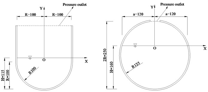
The finite volume and explicit VOF techniques in the Fluent Code are employed to simulate nonlinear parametric sloshing in the tanks. The two tanks are both excited by a vertical acceleration , in which and are respectively the amplitude and frequency of the sinusoidal excitation. The top boundaries of the tanks are defined as the pressure outlets (), as shown in Fig. 1. The rest boundaries of the tanks are defined as no slip walls. Quadrilateral structured meshing is done for the given control volume to reduce the accumulated error. The effect of the surface tension is not included in the numerical model. The model and parameter settings for the Fluent Code are presented in Table 2.
Table 2Model and parameter settings for the fluent code
Model and parameter | Setting |
Solver type model | Pressure-Based Multiphase, VOF |
Spatial discretization pressure | PRESTO |
Viscous model | RNG - |
Tracking free surface method | Geo-Reconstruct |
Water Viscosity (kg/m-s) | 0.001 |
Water Density (kg/m3) Air Viscosity (kg/m-s) Air Density (kg/m3) | 998.2 1.789×10⁻⁵ 1.225 |
Y-Gravity (m/s2) Time step size (s) | –9.81 0.005 |
3. Experimental investigation
In our previous study [13], a two-dimensional parametric sloshing experiment was conducted for a fluid in the rectangular, circular and U-shaped tanks. The previous experiment was only for the stability analyses of parametric sloshing, which belongs to the scope of linear parametric sloshing. In present experimental study, we focus on the stead-state responses of liquid, which fall into the scope of the non-linear parametric sloshing.
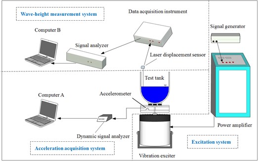
The present test devices, being same as the preceding experiment [13], are illustrated in Fig. 2. The experimental devices consist of three systems, i.e. an excitation system, an acceleration acquisition system and a wave-height measurement system. A sinusoidal signal is respectively produced and amplified by the signal generator and the power amplifier, and then transmitted to the vibration exciter. The vibration exciter exerts a vertical sinusoidal acceleration on the tank. The vertical acceleration signal of the tank is respectively collected, analyzed and recorded by the accelerometer, the dynamic signal analyzer, and computer-A. A laser displacement sensor is fixed on the rigid tank to measure the wave height on the liquid free surface. The light signal is captured by the laser displacement sensor and the data acquisition instrument, and then analyzed and recorded by the signal analyzer and computer-B, respectively.
Fig. 2Experimental diagram
The test tanks, made of Plexiglas, are constructed as the flat-shape containers so as to simulate the two-dimensional sloshing. The height and width of the filled water are same as the numerical models shown in Fig. 1. The water is dyed white so that the liquid free surface can reflect the light that the laser sensor emits. The principal parametric sloshes (resonances) in the U-shaped and circular tanks can be respectively aroused by the vibration exciter in the unstable domains, which were discussed in details in [13].
4. Comparison between numerical and experimental results
4.1. The natural frequency
When the forcing frequency of the vertical acceleration is about twice the th natural frequency of fluid, the principal (sub-harmonic) parametric slosh of mode can be excited by the vertical acceleration. After the excitation is stopped, the free-attenuation responses of wave-height in mode j can be numerically and experimentally obtained, respectively, and the natural frequencies can be calculated by using FFT. The measured locations of wave height for the two tanks are shown in Tables 3 and 4 (see Fig. 1). The numerical solutions and experimental values of the first four natural frequencies for the two tanks are respectively presented in Tables 3 and 4, in which the measured frequencies were obtained in the previous study [13]. The maximum relative errors of the frequencies between numerical and measured values are within 1.6 % accuracy. The numerical solutions agree well with the experimental results. It is shown that the Fluent Code (finite volume and VOF techniques) can accurately calculate the natural frequencies of sloshing fluid in the irregular tanks.
Table 3The I-IV natural frequencies (U-shape tank)
Numbers of mode | Fluent code (Hz) | Measured (Hz) [13] | Measured location of wave height (mm) | Error values (%) |
I | 1.85 | 1.85 | –85 | 0.00 |
II | 2.70 | 2.74 | 0.0 | 1.48 |
III | 3.40 | 3.38 | –33.0 | 0.73 |
IV | 3.90 | 3.90 | 0.0 | 0.05 |
Table 4The II-IV natural frequencies (Circular tank)
Numbers of mode | Fluent code (Hz) | Measured (Hz) [13] | Measured location of wave height (mm) | Error values (%) |
II | 2.49 | 2.53 | 0.0 | 1.6 |
III | 3.10 | 3.09 | –40.0 | 0.10 |
IV | 3.60 | 3.58 | 0.0 | 0.33 |
4.2. Stead-state amplitude-frequency responses
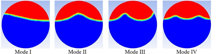
The principal parametric sloshes (resonances) of the first four modes in the U-shaped and circular tanks can be respectively aroused in the unstable domains. The full time-history responses of the wave height of the first four resonances are respectively simulated and measured by the numerical and experimental methods. The measured locations of wave height for the two tanks are same as those in Section 4.1, as shown in Tables 3 and 4. Fig. 3 and 4 respectively show the free surface shapes of principal parametric resonances of modes I-IV for the U-shaped and circular tanks.
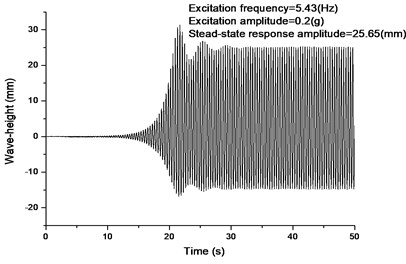
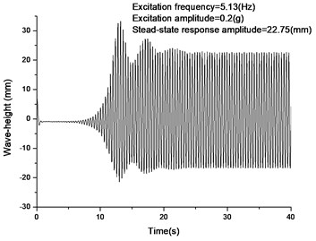
The two typical time-history response curves of the 2nd-mode principal parametric sloshes in the U-shaped and circular tanks are respectively presented in Figs. 5 and 6, from which it can be seen that each free surface elevation (at 0.0) experiences an unstable process, and then turns into a steady-state oscillation or a limit-cycle motion. In the steady-state phase, the wave amplitudes exceed the range of linear motion, and the upward amplitudes are greater than the downward amplitudes. It should be pointed out that the full time-history response curve of wave-height depends on the initial conditions of the free liquid surface. Because the initial disturbances (conditions) in the test are random and cannot be measured accurately, it is difficult to compare the numerical and experimental time-history curves in one figure. However, the stead-state wave amplitudes of parametric sloshing do not rely on the initial conditions. It can be found from Figs. 5 and 6 that the numerical and experimental wave amplitudes agree well.
Fig. 3Free surface shapes of principal parametric resonances of modes I-IV (U-shape tank)
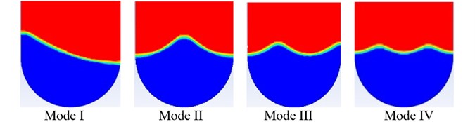
a) Numerical simulation
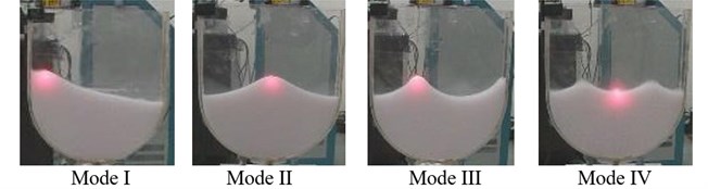
b) Experimental simulation
Fig. 4Free surface shapes of principal parametric resonances of modes I-IV (Circular tank)
a) Numerical simulation
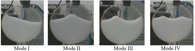
b) Experimental simulation
According to the stability-boundary charts of sub-harmonic response (principal parametric resonance) in [13], if the exciting amplitude is fixed, then there is an unstable frequency domain for each sloshing mode. In each unstable domain, the steady-state wave amplitude varies with the driving frequency.
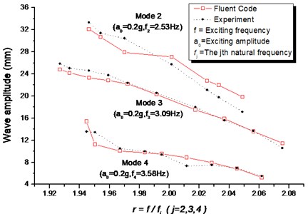
Figs. 7 and 8 respectively show the stead-state (upward) amplitude-frequency responses in unstable regions for the principal parametric resonances in the U-shaped and circular tanks (modes II-IV). The calculated locations on liquid surface of wave height are same as the measured locations (see Tables 3 and 4). It can be seen from Figs. 7 and 8 that the numerical solutions agree well with the experimental results.
It can be found that the wave magnitude suddenly reaches to zero at the two endpoints of the unstable regions. These “jump” behaviors are similar to the other experimental observations (e.g. Dodge et al. [10]). From Figs. 7 and 8, it can also be found that the left-to-right amplitude gradually decreases with the increase of forcing frequency. This behavior of parametric sloshing is similar to that in the cylindrical tank [10].
It is noted that when the resonance of mode 1 occurs in the circular tank, the surface wave will overturn at the wall so that the wave-height near the wall is difficult to measure. As a result, the stead-state amplitude-frequency response of mode 1 in the circular tank is not extracted here.
The numerical method (Fluent Code) can do a reasonably good job of modeling the nonlinear parametric sloshing, and give a good prediction of the wave (upward) amplitudes.
Fig. 5Numerical and experimental wave-height responses (at x= 0.0) of principal parametric resonance of mode II under the same excitation (U-shape tank)
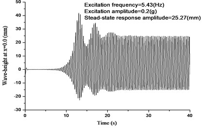
a) Numerical result
b) Experimental result
Fig. 6Numerical and experimental wave-height responses (at x= 0.0) of principal parametric resonance of mode II under the same excitation (Circular tank)
a) Numerical result
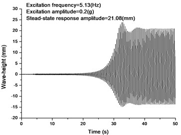
b) Experimental result
Fig. 7Stead-state amplitude-frequency responses of the I-IV mode principal parametric resonances in the unstable domains (U-shape tank)
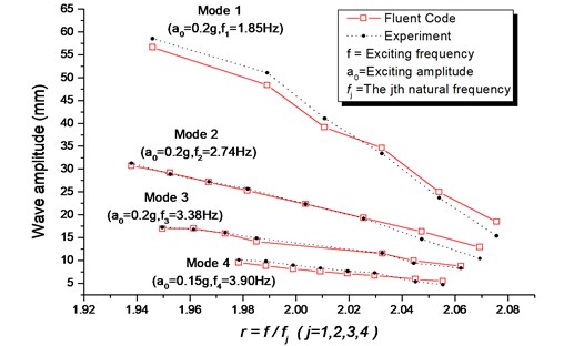
Fig. 8Stead-state amplitude-frequency responses of the II-IV mode principal parametric resonances in the unstable domains (circular tank)
5. Conclusions
The finite volume and VOF techniques (Fluent Code) were successfully applied for predicting the two-dimensional non-linear parametric sloshing. A two-dimensional parametric sloshing experiment was conducted for a fluid in the U-shape and circular tanks. The natural sloshing frequencies and the long time-history stead-state responses of free surface elevations were respectively obtained by numerical and experimental methods. The numerical and experimental results agree well. The finite volume and VOF techniques (Fluent Code) are the efficient tools for solving the long-time nonlinear parametric sloshes in the general irregular tanks, and can give a good prediction of the stead-state wave amplitude. The finite volume and VOF techniques aided by Fluent Code can be a practical tool for the engineers to analyze the nonlinear parametric sloshing. The mechanism of nonlinear stead-state parametric sloshing needs a further study.
References
-
Ibrahim R. A. Recent advances in physics of fluid parametric sloshing and related problems. Journal of Fluids Engineering, ASME, Vol. 137, 2015, p. 090801-1-52.
-
Ibrahim R. A. Liquid Sloshing Dynamics: Theory and Applications. Cambridge University Press, Cambridge, 2005.
-
Faraday M. On a peculiar class of acoustical figures; and on certain forms assumed by groups of particle upon vibrating elastic surfaces. Philosophical Transactions of the Royal Society of London, Vol. 121, 1831, p. 299-340.
-
Dodge F. T. The New Dynamic Behavior of Liquids in Moving Containers. Southwest Research Institute, San Antonio, Texas, 2000.
-
Cui D., Yan S, Guo X., Gao R. X. Parametric resonance of liquid sloshing in partially filled spacecraft tanks during the powered-flight phase of rocket. Aerospace Science and Technology, Vol. 35, 2014, p. 93-105.
-
Faltinsen O. M., Timokha A. N. Sloshing. Cambridge University Press, Cambridge. 2009.
-
Lu L., Jiang S., Zhano M., Tang G. Two-dimensional viscous numerical simulation of liquid sloshing in rectangular tank with/without baffles and comparison with potential flow solutions. Ocean Engineering, Vol. 108, 2015, p. 662-677.
-
Benjamin T. B., Ursell F. The stability of the plane free surface of a liquid in vertical periodic motion. Proceedings of the Royal Society of London. Series A, Mathematical and Physical Sciences, Vol. 225, 1954, p. 505-515.
-
Abramson H. N. The Dynamic Behavior of Liquids in Moving Containers. National Aeronautics and Space Administration, Washington, D.C., 1966.
-
Dodge F. T., Abramson H. N., Kana D. D. Liquid surface oscillations in longitudinally excited rigid cylindrical containers. AIAA Journal, Vol. 3, Issue 4, 1965, p. 685-695.
-
Woodward J. H., Bauer H. F. Fluid behavior in a longitudinally excited, cylindrical task of arbitrary sector-annular cross section. AIAA Journal, Vol. 8, 1970, p. 713-719.
-
Kumar K. Linear theory of Faraday instability in viscous liquids. Proceedings of the Royal Society of London. Series A: Mathematical, Physical and Engineering Sciences, Vol. 452, 1996, p. 1113-1126.
-
Li Y., Wang Z. Unstable characteristics of two-dimensional parametric sloshing in various shape tanks: theoretical and experimental analyses. Journal of Vibration and Control, 2015, 10.1177/1077546315570716.
-
Frandsen J. B. Sloshing motions in excited tanks. Journal of Computational Physics, Vol. 196, 2004, p. 53-87.
-
Horsley D. E., Forbes L. K. A spectral method for Faraday waves in rectangular tanks. Journal of Engineering Mathematics, Vol. 79, 2013, p. 12-33.
-
Kolukula S. S., Chellapandi P. Finite element simulation of dynamic stability of plane free-surface of a liquid under vertical excitation. Modelling and Simulation in Engineering, Vol. 2013, 2013, p. 252760, http://dx.doi.org/10.1155/2013/252760.
-
Wang L., Wang Z., Li Y. A SPH simulation on large-amplitude sloshing for fluids in a two-dimensional tank. Earthquake Engineering and Engineering Vibration, Vol. 12, Issue 1, 2013, p. 135-142.
-
Faltinsen O. M., Rognebakke O., Lukovsky I. A., Timokha A. N. Multidimensional modal analysis of nonlinear slsohing in rectangular tank with finite water depth. Journal of Fluid Mechanics, Vol. 407, 2000, p. 201-234.
-
Faltinsen O. M., Timokha A. N. A multimodal method for liquid sloshing in a two-dimensional circular tank. Journal of Fluid Mechanics, Vol. 665, 2010, p. 457-479.
-
Faltinsen O. M., Timokha A. N. Multimodal analysis of weakly nonlinear sloshing in a spherical tank. Journal of Fluid Mechanics, Vol. 719, 2013, p. 129-164.
-
Henderson D. M., Miles J. W. Surface-wave damping in a circular cylinder with a fixed contact line. Journal of Fluid Mechanics, Vol. 275, 1994, p. 285-299.
-
Miles J. W., Henderson D. M. A note on interior vs. boundary-layer damping of surface waves in a circular cylinder. Journal of Fluid Mechanics, Vol. 364, 1998, p. 319-323.
-
Versteeg H. K., Malalasekera W. An Introduction to Computational Fluid Dynamics: the Finite Volume Method. Longman Group Limited, England, 1995.
-
Hirt C. W., Nichols B. D. Volume of fluid (VOF) method for the dynamics of free boundaries. Journal of Computational Physics, Vol. 39, Issue 1, 1981, p. 201-225.
-
Thiagarajan K. P., Rakshit D., Repalle N. The air-water sloshing problem: Fundamental analysis and parametric studies on excitation and fill levels. Ocean Engineering, Vol. 38, Issue 2, 2011, p. 498-508.
-
Noh W. F., Woodward P. SLIC (simple line interface calculation). Proceedings of the 5th International Conference on Numerical Methods in Fluid Dynamics, 1976, p. 330-340.
-
Ubbink O. Numerical Prediction of Two Fluid Systems with Sharp Interfaces. Ph.D. Thesis, University of London, UK, 1997.
-
Youngs D. L. Time-dependent multi-material flow with large fluid distortion. Numerical Methods for Fluid Dynamics, Vol. 24, 1982, p. 273-285.
-
Gopala V. R., van Wachem B. G. Volume of fluid methods for immiscible-fluid and free-surface flows. Chemical Engineering Journal, Vol. 141, Issue 1, 2008, p. 204-221.
Cited by
About this article

This study is supported by the National Science Foundation of China (Grant No. 51279133). The authors gratefully acknowledge this financial support.
