Abstract
The calculation of natural frequencies is very significant at the design phase of marine propulsion shafts. And added mass of propellers has high effect on natural frequencies. At present, the effect of wake shedding from the propeller’s trailing edge on added mass is unclear. Then their influence on propulsion shafts natural frequencies is also vague. So in this study, the influence of wake shedding on propellers added mass and propulsion shafts natural frequencies is evaluated. Our results show that first, for the first lateral natural frequency, the max relative error reaches up to 6.52 % if the wake shedding is ignored. So for the lateral vibration, the wake should be considered. Second for the first torsion natural frequency, the max relative error amounts to 5.10 % when the skew angle is 108 degrees. So for the torsion vibration, the wake should also be considered when the skew angle is large. Third, for the axial vibration, the influence of wake is little and may be ignored.
1. Introduction
Propulsion shafting is an important unit of marine components. It consists of a shaft, propeller and some support bearings. Usually, vibrations are inevitable for propulsion shafts because the propeller has inescapable eccentricity due to machining accuracy or wear and tear. Meanwhile, the propeller also suffers from large fluid pulse pressure due to the non-uniform flow. Vibrations of propulsion shafts have great effect on crew comfort, ship equipment strength and consequently on the ship safety. Therefore, the dynamic analyses for propulsion shafts are very important for designers. Many studies [1, 2] have investigated about the vibration characteristics and vibration control of propulsion shafts, including the prediction of natural frequencies and mode shapes, the calculation of forced vibrations and so on. At the design stage of propulsion shafts, natural frequencies and mode shapes must be analyzed to know the possible resonance speed. And it is also very important to evaluate them to avoid the resonance phenomena that can be caused by periodic forces of propulsion engine and propeller. Generally, in the dynamic model of the propulsion shaft system, the shaft could be assumed to be a beam supported with some linear springs in bearing points and the propeller could be considered as a lumped mass attached to the end of the beam. So, the mechanical attributes of the entire system could be described with relative clarity. But there are still some problems to predict natural frequencies. One of the reasons is that the propeller immerses in water and fluid-structure interaction occurs. The fluid force has great influence on propulsion shaft vibrations. Some studies [3, 4] show that part of these forces are proportional to vibration acceleration of wetted surface. Therefore, these forces can be replaced by added mass. Added mass is usually significant because on the one hand, it reaches nearly up to the propeller self-mass in some cases, and on the other hand, the added mass will play a dominant role in the entire system, due to the propeller location at a free end of the shaft like a cantilever beam with large mass at its end. So, the added mass cannot be omitted in the dynamic analysis of the propulsion shaft system. The natural frequencies of the shaft are significantly lower than those in air due to added mass. So even the self-mass properties of the propeller can be found without much difficulty, it is the added mass that is the great challenge to calculate the natural frequencies. Some studies dealt with added mass about propellers are simple and imprecise. For example, Murawski and Charchalis [5] studied torsional vibrations of propulsion shafts and Murawski [6] also investigated axial vibrations. Zou et al. [1, 7, 8] analyzed nonlinear forced vibrations of a marine propulsion shaft. In these studies, the added mass was estimated using empirical equations. Exact calculation of propellers added mass is important to accurately predict natural frequencies of propulsion shafts. There are some studies about the calculation of added mass caused by fluid. Lamb [9] described the calculation method about added mass in detail. But it is main to non-lifting bodies and the geometry shape is simple (e.g. cylinders and spheres). For lifting bodies (e.g. propeller), there is vortex shedding (wake vortex) from a sharp edge (e.g. the trailing edge of a propeller when it rotates). This wake is usually called the wake shedding or trailing vortex wake in ship engineering. It is controversial about the effect of the wake vortex on added mass. So its effect on natural frequencies is also unclear.
On the one hand, some studies think the effect of wake on added mass could be ignored. For example, Lee et al. [10] studied hydroelastic responses of marine propellers. Hutchison et al. [11] studied ducted propellers added mass. Ghassemi and Yari [12] evaluated the added mass of marine propellers. Lin and Tsai [13] analyzed free vibrations of a composite propeller blade. In these analysis, the effect of wake shedding was ignored. On the other hand, some studies think the wake has important effect on added mass. For example, Michelin [14] thought that the separation and vortex shedding had significant influence on added mass when the body had a sharp edge. These vortices could produce the thrust and drag. He et al. [15] calculated the propeller added mass. Esch et al. [16] evaluated the added mass of propellers due to torsional and axial vibrations. Their analysis showed the wake shedding had an influence on the magnitude. Young [17, 18] calculated the added mass about the flexible composite propellers. In these analyses, the effect of wake shedding was considered. In addition, Gaschler and Abdel-Maksoud [19] studied the hydrodynamic mass coefficients for a cavitation and non-cavitation marine propeller. The non-rotating (in this case, the effect of wake was ignored) and rotating (in this case, the effect of wake was included) conditions were considered. MacPherson et al. [20] also estimated the axial and torsional added mass with rotating and non-rotating conditions.
To sum up, it is unclear about the effect of the wake shedding on added mass for marine propellers. Some studies think the wake could be ignored and some studies don’t think so. But no papers make a comparison between the case with consideration of wake shedding and the case without wake shedding. And no papers evaluate the effect of wake shedding on natural frequencies of propulsion shafts. Therefore, the comparison and evaluation of the influence of wake shedding on propellers added mass and propulsion shafts natural frequencies are the subject of this paper.
2. Mathematical formulations
In our study, the natural frequencies of propulsion shafts are calculated by FEM, and the added mass of propellers is determined by BEM. The detail description of the formulation and implementation is provided below.
2.1. Calculation of natural frequencies
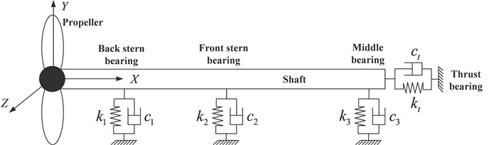
A typical marine propulsion shafts is composed of a shaft, propeller, back stern bearing, front stern bearing, middle bearing and thrust bearing, which is illustrated in Fig. 1. In general, the propeller vibrates with the end of a shaft. It is assumed that the displacement of the end shaft is . Many investigations in linear rotor dynamics deal with the problems of natural, unbalance and transient vibrations. Powerful approximation methods, e.g., the finite element method (FEM), are available for solving these problems. So, in our study, the FEM is applied to solve the natural frequencies.
Fig. 1A diagram of a typical marine propulsion shafts
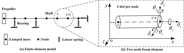
In the FEM model, the shaft is simulated with Timoshenko beam element which has six degree of freedom. The bearings are modelled by linear spring element. The propeller is modelled by lumped mass element. The FEM model is showed in Fig. 2.
Fig. 2The FEM model of propeller-shaft-bearings system
The system equation of motion can be expressed as [21]:
where , and are the global mass, damping and stiffness matrices respectively. The detail formulation of , and  could see the reference [21]. is the added mass matrix of propellers. is external loads.
The natural frequencies can be obtained by solving the following equations:
where is the natural frequency.
So, the added mass of propellers is an important parameter for the calculation of natural frequencies. It would decrease natural frequencies compared with those in air. The next section will describe the method for determining the added mass.
2.2. Calculation of added mass
Young [17, 18] have calculated the added mass about the flexible composite propellers with the boundary element method (BEM). But in their analysis, the propeller is elastic body and has infinite degrees of freedom. So, the added mass is distributional and should be expressed combined with FEM. In this study, the boundary element method described by Young is modified and fit for solving the added mass of rigid body which has six degrees of freedom.
2.2.1. Basic theory
The following assumptions are employed. (1) the flow is inviscid, incompressible, and irrotational; (2) the propeller immerses in deep water and the effect of free surface is ignored; (3) cavitation is not considered; (4) the geometry model of wake shedding is linear and prescribed helical surface.
The pressure on the propeller is caused by both parts, first it originates from the steady rotation of the propeller blades through the non-uniform wake field, and second it arises from the propeller vibration [18]. As long as the vibration amplitude is small, independent evaluation of these two pressure is possible. Because the added mass is only relevant to the second part, only the pressure caused by the propeller vibration is studied in this paper. This pressure can be written as (for more detailed derivation, see reference [17, 18]):
where is the perturbation velocity potential due to the propeller vibration. is the inflow velocity of the propeller and is the density of water.
For the perturbation velocity potential , combining the kinematic boundary condition and applying Green’s identity, the following expression can be obtained [22]:
where , are points on the propeller surface . is any point on the wake surface and is potential jump across the wake surface . is the unit normal vector of the propeller surface . is the vibration velocity of the propeller caused by the shaft vibration.
It assumes that the vortex sheets will leave the trailing edge at constant pitch angle, so the wake geometry which could be express as [23]:
where is a constant between 0 and 1. Usually, is set equal to 0.2. is the pitch angle of trailing vortices at radius . is blade pitch angle which depends on the blade geometry. is undisturbed-flow pitch angle, which could be written as determined by the advance coefficient ().
The boundary integral Eq. (4) is hard to solve analytically for complex geometry. So, a numerical solution is obtained by dividing the surface into a number of small elements. It is assumed that the numbers of the panels on the propeller and wake surface are respectively and shown as in Fig. 3 (only one blade wake surface is shown).
Fig. 3Panel arrangement of propeller and wake
The boundary integral Eq. (4) can be expressed in matrix form as:
where is influence coefficient matries and solved by Morino’s analytical formulation [24].
Take the derivative to coordinate (or and ) on both sides of Eq. (4). Similarly, the following matrix form can be obtained:
where is the velocity influence coefficient matrixes and also calculated by Morino’s analytical formulation [24].
2.2.2. Added mass formulation
As shown in Fig. 2, the vibration velocity of the shaft is . For propeller, the coordinate of the th panel center is assumed to be . So, its vibration velocity could be expressed as:
The normal vector of the th panel center is also assumed to be . So could be written as:
where .
According to Eq. (3), then the pressure of the th panel is obtained:
where , , are three coordinate components of vector .
Then the resultant force and moment by all panels could be written as:
where is the area of the th panel and .
In Eq. (11), the first term is proportional to vibration acceleration of the propeller, so it could be called added mass. Similarly, the second term is proportional to vibration velocity and could be called added damping.
So, from Eq. (11), it is known that the added mass could be written as:
In general terms, a propeller vibrates in the six rigid body modes defined in Fig. 2. So, the added mass is six order matrix and has the form [3]:
where is called axial added mass and is called lateral added mass. is called polar added mass moment of inertia and is called diametric added mass moment of inertia. For the added mass matrix, first, several of the terms, for example and , have identical values. Second, the matrix is symmetrical. Third, there also are some non-diagonal coupling terms.
3. Program codes validation studies
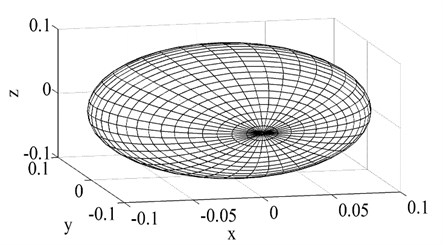
Some numerical convergence and validation studies of the current BEM program codes (with MATLAB) have been conducted in this section. The added mass of a sphere immersed in infinite water is calculated, becasue for it exact analytical results are available. Then the exact results and the numerical results are compared. The radius of the sphere is 0.1 m. According to the analytical solutions in mass matrix, only , and have values and the others are zero due to the geometry shape. The three coefficients are equal with each other. For a non-lifting body, there is no wake shedding from the body. Its panel arrangement is shown in Fig. 4. The mesh numbers on the sphere surface are 1200.
Fig. 4Panel arrangement of the sphere
The calculation values for added mass of the sphere using the BEM codes are as follows:
In Eq. (14), only , and have values and the others are zero, which agrees with the analytical solution. For a sphere, the analytical values of added mass are equal to [25]:
Compared the numerical solutions with the analytical solutions, it is known that the errors between them are very small. In order to evaluate the mesh convergence, the added mass matrix is investigated for three different mesh elements (1200, 2400 and 4800 elements), using the BEM codes and the obtained results and errors are checked. The results are shown in Table 1.
Table 1Comparisons of the BEM and analytical results for different mesh numbers
Mesh numbers | Numerical values | Analytical values | |
1200 | 2.0917 | 2.0944 | 0.13 % |
2400 | 2.0929 | 2.0944 | 0.07 % |
4800 | 2.0938 | 2.0944 | 0.03 % |
It is evident that the convergence characteristics of the mass terms are very good. With the increase of mesh numbers, the numerical values converge to the analytical values.
To sum up, from this example, it can be found that there is a very good accuracy between the numerical solutions and the experiment data or the analytical solutions, suggesting the validity of our BEM program codes written in MATLAB.
4. Numerical example
4.1. The effect of wake on added mass
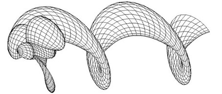
In this section, some numerical examples are considered to examine the influence of the wake vortex emanating from trailing edge on added mass. A series of four five-blade skewed marine propellers originate in practical engineering are evaluated. The parent propeller has a symmetric blade outline with zero skew, and the other three propellers have maximum projected skew angles of 36°, 72° and 108° at the propeller tip. The geometric parameters for all four propellers are the same except skew, pitch, and camber. The propellers each have a diameter of 5 m and the design advance coefficient 0.889. The primary geometries are given in [3, 26], and are shown in Fig. 5.
Fig. 5BEM representation of propeller 4381, 4382, 4383 and 4384 and wake shedding
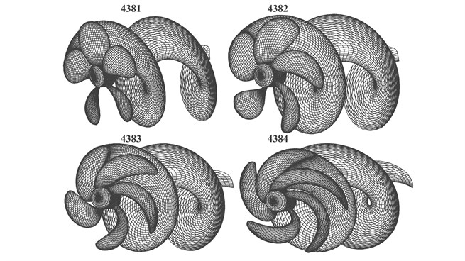
Two models are analyzed, in which one ignores the wake shedding and the other considers it. In the second model, the trajectories of wake shedding are defined by Eq. (5). The shape of wake shedding is shown in Fig. 5 (take one blade wake for example).
The mesh numbers are subdivided as many as possible until the numerical results have little variation and are convergent. These results have been non-dimensionalized by the divisor given in Table 2 (where is the density of water and is the diameter of the propeller).
Table 2Nondimensionalization of added mass
Divisor | Corresponding and number in | Type of coefficient |
1, 2, 3 | Mass terms | |
1, 2, 3; 4, 5, 6 or 4, 5, 6; 1, 2, 3 | Coupling mass terms | |
4, 5, 6 | Mass moment of inertia terms |
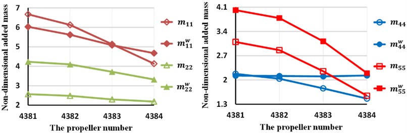
Fig. 6 is the results comparison of the main diagonal added mass between these two cases, in which one ignores wake shedding and the other considers it. The superscript denotes the added mass with consideration of wake shedding. From this figure, it is seen that, first, the wake greatly increases lateral added mass and diametric added mass moment of inertial for all skew angles. Second, the wake has minor influence on polar added mass moment of inertia when the skew angle is not large (such as propeller 4381 and 4382). As the skew angle increases, so does the effect of wake on . Third, for axial added mass , the wake has little effect on it when the skew angle is 72 degrees (such as propeller 4383). The wake increases when the skew angle is larger than 72 degrees (such as propeller 4384), and reduces it if the skew angle is smaller than 72 degrees (such as propeller 4381 and 4382).
Fig. 6Comparison of the main diagonal values with and without wake shedding
4.2. The effect of wake on shafts’ natural frequencies
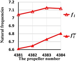
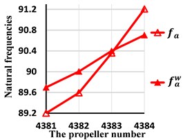
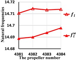
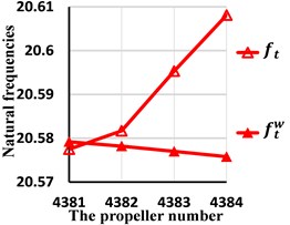
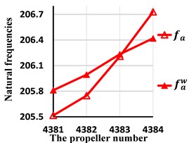
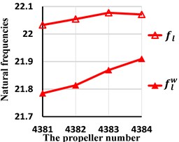
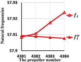
In the previous section, the effect of wake shedding to added mass is discussed. As the introduction says, the ultimate aim of exact calculation the added mass is to predict the natural frequencies accurately. So, in this section, the effect of wake shedding on natural frequencies of propulsion shafts is also studied. Four dynamic models are established according a marine propulsion shafting in practical engineering and the structure is shown in Fig. 1. In these four models, the only difference is the propeller (the propeller is 4381 to 4384 respectively). The length of the shaft is 20 m. The external diameter of the cross section is 500 mm and the internal diameter is 320 mm (to simplify, the shaft is considered as uniform circular in cross section). The Young’s modulus is 210 GPa and the Poisson’s ratio is 0.33. The density is 7800 Kgm-3. The axial coordinate of transverse bearing , and is 2 m, 10.4 m and 20 m respectively. The stiffness are all 3e8 Nm-1. The axial coordinate of thrust bearing is 20 m and the stiffness is 5e8 Nm-1. Most parameters of the shaft come from the reference [27] and a small number of them, for example the thrust bearing stiffness, come from our experience. The natural frequencies of two models are calculated. In one model, the added mass is without wake shedding and in the other model, the added mass is with wake shedding. Then these results are compared with each other. and are defined as the axial (longitudinal) natural frequencies with or without wake respectively. Similarly, and are defined as the lateral (transverse) natural frequencies. and are defined as the torsion natural frequencies. The first three natural frequencies are studied and these results are shown in Fig. 7 to Fig. 9. Meanwhile, the relative errors are defined and shown in Table 3 to Table 5.
Fig. 7Comparison of the first natural frequencies with and without wake shedding
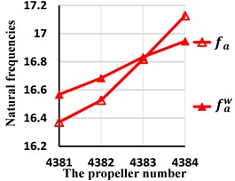
a) The axial natural frequencies
b) The lateral natural frequencies
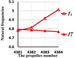
c) The torsion natural frequencies
From these tables and figures, some conclusions can also be obtained. First, for lateral, axial and torision vibration, because the first natural frequencies occur near the propeller and the second, the third occur away from the propeller, the wake shedding only has effect on the first natural frequencies. Second, the first lateral natural frequency is smaller than for any skew angle. The smaller the skew angle is, the larger the relative error will be. Even if the skew angle is 108 degrees, the relative error reaches up to 4.63 %. So, the wake shedding has important effect on lateral natural frequencies and should be considered. Second, the wake has great impact on the first torsion natural frequency when the skew angle is large. For example, when the skew angle is 108 degrees, the relative error amounts to 5.10 %. As the skew angle is small, the wake could be ignored. Third, for axial vibration, the influence of wake is little and may be ignored for all skew angles.
Fig. 8Comparison of the second natural frequencies with and without wake shedding
a) The axial natural frequencies
b) The lateral natural frequencies
c) The torsion natural frequencies
Fig. 9Comparison of the third natural frequencies with and without wake shedding
a) The axial natural frequencies
b) The lateral natural frequencies
c) The torsion natural frequencies
Table 3The relative errors of the first natural frequencies
4381 | 4382 | 4383 | 4384 | |
1.18 % | 0.95 % | 0.09 % | 1.07 % | |
6.52 % | 6.51 % | 5.90 % | 4.63 % | |
0.28 % | 0.57 % | 2.92 % | 5.10 % |
Table 4The relative errors of the second natural frequencies
4381 | 4382 | 4383 | 4384 | |
0.55 % | 0.45 % | 0.05 % | 0.55 % | |
0.15 % | 0.17 % | 0.13 % | 0.11 % | |
0.008 % | 0.017 % | 0.089 % | 0.157 % |
Table 5The relative errors of the third natural frequencies
4381 | 4382 | 4383 | 4384 | |
0.14 % | 0.12 % | 0.01 % | 0.15 % | |
1.14 % | 1.10 % | 0.95 % | 0.74 % | |
0.002 % | 0.003 % | 0.016 % | 0.028 % |
5. Conclusions
In this study, the influence of wake shedding from the propeller trail edge on natural frequencies is investigated. The most important results can be expressed as:
1) For lateral, axial and torsion vibration, the wake shedding has great effect on the first natural frequencies compared with the others. This because the first natural frequencies occur near the propeller.
2) For the first lateral natural frequency, the max relative error reaches up to 6.52 % if the wake shedding is ignored. So, for the lateral vibration, the wake should be considered.
3) For the first torsion natural frequency, the max relative error amounts to 5.10 % when the skew angle is 108 degrees. So, for the torsion vibration, the wake shedding should also be considered when the skew angle is large.
4) For the axial vibration, the influence of wake is little and may be ignored.
References
-
Zou D., Rao Z., Ta N. Coupled longitudinal-transverse dynamics of a marine propulsion shafting under superharmonic resonances. Journal of Sound and Vibration, Vol. 346, 2015, p. 248-264.
-
Qianwen H., Cong Z., Yong J., Chengqing Y., Xinping Y. Vibration analysis of marine propulsion shafting by the coupled finite element method. Journal of Vibroengineering, Vol. 17, Issue 7, 2015, p. 3392-3403.
-
Carlton J. Marine Propellers and Propulsion. 2th Ed. Butterworth-Heinemann, Oxford, 2012.
-
Newman J. N. Marine Hydrodynamics. MIT Press, Cambridge, Mass, 1977.
-
Murawski L., Charchalis A. Simplified method of torsional vibration calculation of marine power transmission system. Marine Structures, Vol. 39, 2014, p. 335-349.
-
Murawski L. Axial vibrations of a propulsion system taking into account the couplings and the boundary conditions. Journal of Marine Science and Technology, Vol. 9, Issue 4, 2004, p. 171-181.
-
Zou D., Liu L., Rao Z., Ta N. Coupled longitudinal–transverse dynamics of a marine propulsion shafting under primary and internal resonances. Journal of Sound and Vibration, Vol. 372, 2016, p. 299-316.
-
Zou D., Jiao C., Ta N., Rao Z. Forced vibrations of a marine propulsion shafting with geometrical nonlinearity (primary and internal resonances). Mechanism and Machine Theory, Vol. 105, 2016, p. 304-319.
-
Lamb H. Hydrodynamics. 6th Ed. Dover, New York, 1932.
-
Lee Hyoungsuk, Song Min-Churl, Suh Jung-Chun, Chang B.-J. Hydro-elastic analysis of marine propellers based on a BEM-FEM coupled FSI algorithm. International Journal of Naval Architecture and Ocean Engineering, Vol. 6, 2014, p. 562-577.
-
Hutchison S., Steen S., Sanghani A. Numerical investigation of ducted propeller added mass. Proceedings of the Third International Symposium on Marine Propulsors Symposium, Tasmania, Australia, 2013, p. 69-77.
-
Ghassemi H., Yari E. The added mass coefficient computation of sphere, ellipsoid and marine propellers using boundary element method. Polish Maritime Research, Vol. 18, Issue 1, 2011, p. 17-26.
-
Lin H. J., Tsai J. F. Analysis of underwater free vibrations of a composite propeller blade. Journal of Reinforced Plastics and Composites, 2008, p. 1-12.
-
Michelin S. H. R. Falling, flapping, flying, swimming,...: high-Re fluid-solid interactions with vortex shedding. Aerospace Engineering, University of California, San Diego, 2009.
-
He X. D., Hong Y., Wang R. G. Hydroelastic optimisation of a composite marine propeller in a non-uniform wake. Ocean Engineering, Vol. 39, 2012, p. 14-23.
-
van Esch B., van Hooijdonk J., Bulten N. Quantification of hydrodynamic forces due to torsional and axial vibrations in ship propellers. ASME 2013 Fluids Engineering Division Summer Meeting, American Society of Mechanical Engineers, Nevada, USA, 2013, p. 1-8.
-
Young Y. L. Fluid-structure interaction analysis of flexible composite marine propellers. Journal of Fluids and Structures, Vol. 24, Issue 6, 2008, p. 799-818.
-
Young Y. L. Time-dependent hydroelastic analysis of cavitating propulsors. Journal of Fluids and Structures, Vol. 23, Issue 2, 2007, p. 269-295.
-
Gaschler M., Abdel-Maksoud M. Computation of hydrodynamic mass and damping coefficients for a cavitating marine propeller flow using a panel method. Journal of Fluids and Structures, Vol. 49, 2014, p. 574-593.
-
MacPherson D. M., Puleo V. R., Packard M. B. Estimation of Entrained Water Added Mass Properties for Vibration Analysis. SNAME, New England, 2007.
-
Rao J. History of Rotating Machinery Dynamics. Springer Science and Business Media, 2011.
-
Joseph Katz A. P. Low-Speed Aerodynamics. 2th Ed. Cambridge University Press, Cambridge, 2001.
-
Yumin S., Sheng H. The Theory of Marine Propellers. Harbin Engineering University Press, Harbin, 2013, (in Chinese).
-
Morino L., Kuot C.-C. Subsonic potential aerodynamics for complex configurations: a general theory. AIAA Journal, Vol. 12, Issue 2, 1974, p. 191-197.
-
Korotkin A. I. Added Masses of Ship Structures. Springer Science and Business Media, New York, 2008.
-
Boswell R. J. Design, Cavitation Performance, and Open-Water Performance of a Series of Research Skewed Propellers. NSRDC Report, 1971.
-
Chen Z. The Vibration of the Marine Propulsion Shafting. Shanghai Jiao Tong University Press, Shanghai, 1987, (in Chinese).
About this article

