Abstract
Dynamic property of a gas face seal is about an internal ability of the mass-spring-damper system consisting of the nonlinear gas film, the flexible support, and the component mass or moment of inertia to handle ambient disturbances. Stability and tracking properties are important dynamic components, the current research for which mainly focuses on high-speed and high-pressure conditions in turbomachinery applications. In this paper, perturbation theory is used to obtain the linearized properties of the gas film in a spiral groove gas face seal, where the Boltzmann-Reynolds model with Fukui-Kaneko approximation is involved to account for slip flow under low-parameter conditions. Transmissibility of the step jump method is introduced into the perturbation method, and a critical ambient-disturbance amplitude is further proposed to cover the defect of transmissibility in characterizing the tracking property. The effects of slip flow on the stability and tracking properties of gas face seals are explored. The results show that slip flow induces an extra “relaxation region” in the critical transverse moment of inertia, providing a softer demand for angular stability. With regard to transmissibility, slip flow will induce an advantageous effect on transmitting the rotor motion to the stator. However, after considering the space required for tracking motions, the results of critical amplitude indicate that slip flow will induce an extra “rigorous region”, leading gas face seals to require more conservative design and more rigorous manufacture and assembly for non-contacting tracking.
1. Introduction
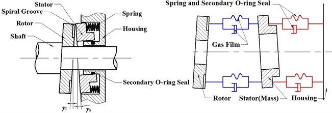
A spiral groove gas face seal (Fig. 1) is a type of non-contacting face seals that prevents sealed gas from escaping from one compartment to another. A well designed gas face seal should have an appropriate dynamic property to head off excessive leakage and face contact [1, 2]. As depicted in Fig. 1, the dynamic system of a gas face seal is a typical mass-spring-damper system which consists of the nonlinear gas film stiffness and damping, the flexible support, and the mass and the transverse moment of inertia of the stator. Thus, the dynamic property of a gas face seal is about a systematic internal ability to handle ambient disturbances, which typically include axial endplay and angular wobble. The axial endplay of the rotor is caused by the axial endplay of the shaft, and the angular wobble of the mated rings is a result of manufacturing and assembly tolerances such as the runouts of both rings and the imperfection in the stator’s flexible support. When subjected to these disturbances, the stator may become completely unstable. Even in a stable state, an improper tracking property can still either induce excessive leakage or local face contact [3, 4]. It is therefore imperative to study the stability and tracking properties of gas face seals which have played important dynamic roles in other applications [5, 6].
Dynamic research on gas face seals has been performed using both direct numerical methods [7-11] and semi-analytical methods [12-17]. In such research, the stability and tracking properties of gas face seals act as important focal points. Green and Barnsby [8] used the state-space-form method developed by Miller and Green [9] to gauge the influence of sealing parameters on the stability threshold of coned gas face seals. The tracking property of the stator was also discussed by a parametric investigation [10]. Zirkelback and San Andres obtained the axial stiffness and damping coefficients of the gas film in a spiral groove gas face seal using a perturbation method [12], and subsequently presented a corresponding stability analysis [13]. Ruan [14] added angular motions to the dynamics to further develop the perturbation method, and presented a simple stability analysis. Meanwhile, Miller and Green developed a step jump method [15, 16] to provide a stability and tracking analysis of spiral groove gas face seals [17]. Because gas face seals are usually used in high-speed and high-pressure turbomachinery, all of the above works have been performed under high-parameter conditions.
Fig. 1Schematic of a typical spiral groove face seal and equivalent mass-spring-damper representation
With the continuing development of gas face seals, the applications of these seals are expanding to devices such as mixers and agitators, where the speed and pressure represent comparatively low-parameter conditions [18]. Such low-parameter conditions can even exist in high-parameter turbomachinery in scenarios such as debugging and engine warm up. In such applications, the continuum-flow assumption of the gas film breaks down and the rarefaction effect becomes significant. First- [19], second- [20], and 1.5-order [21] slip flow models have been developed to modify the classical continuum-flow Reynolds equation, accounting for rarefaction effects by allowing molecular slipping to occur at the gas-wall interface. Fukui and Kaneko developed a Boltzmann-Reynolds model for an arbitrary Knudsen number based on the linearized Boltzmann equation and provided a database of values in terms of the inverse Knudsen number [22]. Subsequently, they published a set of polynomials for the curve fitting of the above database [23]. These slip flow models have been used in the analysis of gas face seals. Pecht and Netzel [24] and Ruan [18] gauged the effect of slip flow on the steady-state performance of gas face seals including lift-off speed, leakage rate, frequency-independent gas film stiffness and load carrying capacity. Ruan [25] also considered slip flow in a study on the transient performance of spiral groove gas face seals during the startup and shutdown operations. However, few previous works have researched the stability and tracking properties of gas face seals under low-parameter conditions.
The objective of the present study is to provide an investigation of the effect of slip flow on the stability and tracking of spiral groove gas face seals under low-parameter conditions. In addition, the approach used to analyze stability and tracking properties can still be improved. In direct numerical methods [7-11], the stability and tracking properties are analyzed numerically, but this approach is inefficient for intensive parametric analyses. In the perturbation method [12-14], it is convenient to obtain expressions for the critical stability condition because of the existence of linearized gas film coefficients in the time domain. Yet, the tracking property is still characterized by axial relative displacement or angular relative tilt angle. In the step jump method [17], the transmissibility is presented in the form of an expression that can be used to characterize the tracking property. However, the step response, which acts as the constitutive model of gas film, is easy to analyze in the frequency domain [16] but difficult to analyze in the time domain. Therefore, a balanced approach is proposed that introduces the transmissibility into the perturbation method. Furthermore, because the transmissibility only reflects the tracking ability while ignores the space required for tracking motions, critical ambient-disturbance amplitude, above which the seal will achieve face contact, is provided based on the transmissibility to cover the defect of transmissibility in characterizing the tracking property.
2. Model
2.1. Gas film lubrication and sealing dynamics
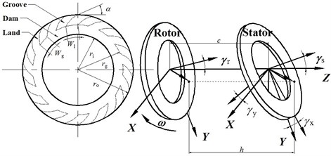
A schematic diagram of a typical gas face seal is shown in Fig. 1. A dynamic schematic of the mated rings and the rotor geometry are depicted in Fig. 2. A total of spiral grooves are processed on the rotor face at a depth of . is the spiral angle and varies from 0 to 180°. The groove width relative to the land width is measured by , and the groove length relative to the dam length is measured by . Here, , and are the dimensionless outer radius, inner radius and boundary of the groove region and dam region, respectively, where , , and . Here, superscript represents the dimensional form of a variable in the present study.
The gas pressure distribution in the gas face seal is governed by the lubrication equation. Assuming that the gas flow is ideal and isothermal, the compressible Reynolds equation is then given by [8-11, 14-17, 25]:
where is the gas viscosity, is the radius, is the unit vector in the direction, is the gas film thickness, is the shaft speed, and is the time. The dimensionless form of Eq. (1) and its corresponding boundary conditions are given by:
where and the compressibility number . Also, and are the pressures at the inner and outer radii. Here, a flow factor is incorporated into Eq. (2a) to modify the compressible Reynolds equation to account for the slip flow [18, 22, 23]:
where is the gas constant, and is the ambient temperature.
The dimensionless rotor tilt angle , the stator tilt angle and the relative tilt angle can be decomposed into components along the and axes:
where , and . The gas film thickness at any point (, ) on the stator face is given by:
where is the dimensionless central film thickness at equilibrium, is the dimensionless axial displacement of the stator from , is the dimensionless axial endplay of the rotor, and indicates a dimensionless groove depth in the groove region. Here, , and . By considering the stiffness and damping properties of the springs and the secondary seal, the dimensionless dynamic equations for the axial and angular modes are given by [9, 14, 17, 25]:
In Eq. (6), is the dimensionless mass, and is the dimensionless transverse moment of inertia of the stator, where and. is the dimensionless axial stiffness of the springs and is the dimensionless axial damping of the flexible support, where and . According to the work of Green and Etsion [26], the dimensionless angular stiffness and the damping are given by:
assuming that the support forces act at the outer radius. is the total load of the fluid pressure and the spring support load at equilibrium, which is applied to the rear of the stator to balance the gas film load caused by the fluid effect. and are the gas film moments about the and axes. is a moment caused by the dimensionless static stator tilt , which is arbitrarily assumed to be oriented about the axis. The constant moment is given by . , and can all be obtained by integrating over the dimensionless sealing area , as follows:
Fig. 2Dynamic schematic of a spiral groove gas face seal and the geometry of the rotor
2.2. Perturbation method
Malanoski and Pan [27] performed a pioneering work in studying the axial gas film coefficients in a spiral groove gas thrust bearing by a perturbation method. Zirkelback and San Andres [12] used the perturbation method to analyze a spiral groove gas face seal. Ruan [14] added angular modes to further develop the perturbation method. In the present study, the perturbation method described in Ref. [14] is adopted. Because our dimensionless approach differs from that of Ref. [14], and because the flow factor is involved, the whole process should be deduced again. If small oscillatory motions (,,) with excitation frequency occur near the equilibrium , Eq. (5) can then be rewritten as:
where, the excitation frequency ratio is introduced because of the dimensionless process for . These small motions cause a small pressure perturbation about the equilibrium pressure . Using a first-order Taylor series expansion, the new pressure can be expressed as:
After substituting Eqs. (9, 10) into Eq. (3a) and only remaining terms of order O(1), O(), O(), O(), O(), O(), O(), the following seven equations can be produced:
The corresponding boundary conditions are given by Eq. (2b) and:
These seven equations can be classified into four groups. Eq. (11) governs the steady-state pressure distribution at equilibrium . Eqs. (12-14) are three pairs of perturbation Reynolds equations that govern three pairs of variables (, ), (, ) and (, ), respectively. For each pair, an iterative process is required to produce stable variables.
Based on Eq. (8), the generalized force in response to the perturbation can be expressed as:
Therefore, the stiffness and damping matrices are:
Because the works of Ruan [14] and Miller and Green [16, 17] indicate that the cross-coupling coefficients can be ignored and that only three terms are unique, the reduced matrices are given by:
2.3. Stability and tracking
2.3.1. Stability
The dimensionless form of the linearized dynamics used for the stability research is given by:
After substituting a small axial displacement into the equation of axial motion, the characteristic equation can then be obtained as:
where the complex number . For the critical condition of axial stability, the real part is zero and Eq. (19) can then be reduced to:
Here, subscript represents the critical condition in the present study. To satisfy Eq. (20), both the real and imaginary parts should be zero. Therefore, the critical excitation frequency ratio and the critical mass for axial stability should satisfy:
Here, an iterative process is inevitable to calculate . It is because before can be solved by Eq. (21a), is required. However, is related to in the perturbation method.
The same method is also used to analyze the angular stability. After substituting small angular displacements and into the equations of angular motions, the dimensionless angular dynamics are transformed into:
Because the determinant of the coefficient should be zero, the characteristic equation is then obtained as:
By considering the real part of to be zero under the critical condition, the critical excitation frequency ratio and the critical transverse moment of the inertia for angular stability can be obtained from Eq. (23), as follows:
where an iterative process is also necessary to calculate of .
2.3.2. Tracking
When the stator satisfies the stability demand, an appropriate tracking property is expected to avoid both excessive leakage and local face contact. Because the typical ambient disturbances are the axial endplay and the angular wobble of the rotor, where in Eq. (6) is ignored, is equal to (i.e., 1) in the tracking study. The dimensionless sealing dynamics for the axial endplay and the angular wobble can then be expressed as:
A Laplace transform approach [14, 17] is then used to solve Eq. (25). The axial and angular motions in the Laplace domain are given by:
where is the Laplace variable. and are the Laplace transforms of and , respectively. and are the Laplace transforms of , , and , respectively. The variables with zero in parentheses are the initial values at 0. If the axial relative displacement or the angular relative tile angle is used to characterize the tracking property [14], the inverse Laplace transform of Eq. (26) can be used to obtain , and numerically or analytically. Here, the transmissibility in the step jump method [17] is introduced into the perturbation method to derive expressions for the characterization of the tracking property.
In the axial mode, the dimensional axial endplay and the corresponding response are assumed to be and and their dimensionless forms are and respectively, where is the axial phase difference, and . By substituting and into the axial motion of Eq. (25), one can obtain:
where is the axial transmissibility, and is the axial relative transmissibility that is demanded to be less than 0.3 in a proper tracking design [28].
In the angular modes, the dimensional angular wobble and the corresponding response are assumed to be and , and their dimensionless forms are and respectively, where is the angular transmissibility, is the angular phase difference, and . A relation similar to Eq. (27) is more difficult to be obtained in the angular modes. The steady-state response to the harmonic angular wobble takes the form of harmonic functions, as follows:
where , , and are the angular amplitude coefficients. By transforming Eq. (28) into the Laplace domain and then substituting the results into Eq. (26b-26c), these angular amplitude coefficients are gathered as:
The real part of corresponds to the tilt angle about the axis, and the imaginary part of corresponds to the tilt angle about the axis. Likewise, the real part of corresponds to the tilt angle about the axis, and the imaginary part of corresponds to the negative tilt angle about the axis. Therefore, and satisfy the following:
If and are expressed as:
the angular transmissibility and the phase difference in the mode can be given by:
Because the transverse moments of inertia and the support properties are symmetrical about the and axes, and . The angular relative tilt angle and the relative transmissibility can then be given by:
The transmissibility can be used to characterize the tracking property. However, it is a ratio to only convey the information about the amplitude rather than the datum line. It is possible to obtain the tracking ability in detail from the transmissibility but it is impossible to see how much space is reserved for the tracking motions. A feasible approach to observe the tracking property including both “amplitude” and “datum line” is to investigate how much the amplitude of axial endplay and angular wobble can be allowed before face contact occurs. Therefore, the critical ambient-disturbance amplitude is provided based on the transmissibility to cover the defect of transmissibility in characterizing the tracking property. Because the linearized coefficients of the gas film are based on small perturbations from the parallel face position, the following results may be not extremely accurate when subject to large deviations. Yet, the validity of this method can be acceptable before a more elaborate analysis becomes available [26]. Even if a more elaborate analysis can be applied, the time cost should be considered. Therefore, the critical condition for face contact is given by:
where the surface texture is not considered. The equation then can be reduced to an expression that contains the transmissibility:
3. Results and discussion
Table 1 lists the parameters of a spiral groove gas face seal. The subsequent simulations under the slip flow and non-slip flow conditions are both performed based on the data in this table. Note that the value of is not measured but selected from Refs. [14, 25] (1 kN∙s/m). It is not a significant factor because the present study focuses on the simulations and is not related to any experimental work. Compressibility number ranging from 2.5233 to 5.8878 (i.e., shaft speed ranges from 300 to 700 r/min) is selected as the representative low-parameter conditions in the simulation. The calculation is performed by using a finite element method. Numerical accuracy and stability are important for a complex dynamic system. A very fine mesh would result in excessive computation time. Therefore, a balance between accuracy and economical computing must be maintained. After the experiments, it is determined that a 3160-finite element mesh is adopted. The calculation is carried out on a 2.3 GHz workstation.
Table 1Parameters of a spiral groove gas face seal
Parameter | Value |
Outer radius | 61.7 mm |
Inner radius | 51.6 mm |
Balance radius | 53.1 mm |
Spiral angle | 15º |
Number of grooves | 12 |
Groove to land width ratio | 0.5 |
Groove to dam length ratio | 0.6 |
Groove depth | 6 μm |
Stator mass | 0.13 kg |
Transverse moment of inertia | 2.5×10⁻⁴ kg∙m2 |
Pressure at outer radius | 0.2 MPa |
Pressure at inner radius | 0.1 MPa |
Support axial stiffness | 16.4 kN/m |
Support axial damping | 1 kN∙s/m |
Gas constant | 300∙K |
Ambient temperature | 287 J/(kg∙K) |
3.1. Fundamental sealing performance
The effect of slip flow on the fundamental seal-performance variables, including the central film thickness at equilibrium, the lift-off speed and the stiffness and damping of the gas film, are analyzed to form the foundation of the following discussion on stability and tracking. Fig. 3 shows the central film thicknesses at equilibrium at different shaft speeds. It can be seen that the central film thickness at equilibrium increases as the shaft speed increases. It is because the closing force is constant in these cases and the hydrodynamic effect is enhanced by the increased shaft speed. A greater central film thickness at equilibrium helps to weaken the hydrodynamic effect to balance the constant closing force. A significant deviation between the two flow approaches is apparent. The central film thickness at equilibrium is smaller under the slip flow condition than under the non-slip flow condition. The relative error decreases as the shaft speed increases because the slip flow is diminishing, which can be visualized from the variation of the minimum inverse Knudsen number from 11.985 at 300 r/min to 22.767 at 700 r/min. A decreased central film thickness at equilibrium caused by the slip flow means that the slip flow will induce a reduced load carrying capacity because of the loss of viscous pumping due to the slippage at the solid boundary. Fig. 4 displays the lift-off speeds at different lift-off thicknesses of 0.6, 0.7, 0.8, 0.9 and 1.0 μm. The lift-off speed increases with the increased lift-off thickness because of the decreased hydrodynamic effect. The lift-off speed is higher under the slip flow condition, and the relative error decreases with the increased lift-off thickness. A higher lift-off speed under the slip flow condition means that if a gas face seal were to start up from rest, its corresponding lift-off would be delayed, and the face of the seal would suffer more severe wear. Therefore, the slip flow should be noted during the startup and shutdown operations accounting for the service life of seals.
Fig. 3Comparison of central film thicknesses at equilibrium c0 at different shaft speeds ω from 300 to 700 r/min (Λ from 2.5233 to 5.8878)
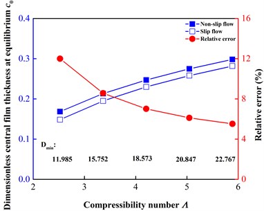
Fig. 4Comparison of lift-off speeds at different lift-off film thicknesses from 0.6 to 1.0 μm (dimensionless values from 0.1000 to 0.1667)
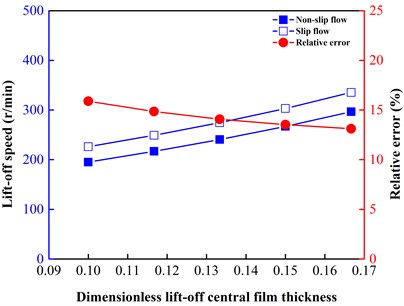
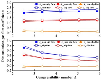
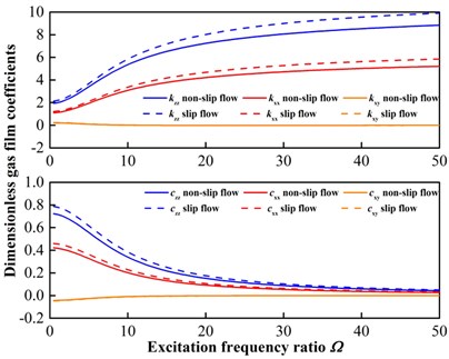
Fig. 5Comparison of frequency dependent stiffness and damping coefficients of gas film. a) Λ varies from 2.5233 to 5.8878 (ω from 300 to 700 r/min) where Ω= 1; b) Ω varies from 0.5 to 50 where Λ= 2.5233 (ω= 300 r/min)
a)
b)
Fig. 5 shows the linearized stiffness and damping coefficients of the gas film by using the perturbation method. In Fig. 5(a), is varied from 2.5233 to 5.8878 (i.e., ranges from 300 to 700 r/min) while is maintained at 1, thus showing the linearized gas film coefficients as a function of (i.e., ). In Fig. 5(b), is maintained at 2.5233 (i.e., 300 r/min) while is varied from 0.5 to 50, thus showing the linearized gas film coefficients as a function of . For each figure, the upper component corresponds to the stiffness, while the lower corresponds to the damping. In contrast with the frequency-independent stiffness of Ref. [18], the stiffness presented here is frequency dependent. For the stiffness, the direct terms, i.e., and , increase with the increased or , but the cross terms, i.e., , decrease with the increased or . The tendency of the stiffness is opposite to that of the damping. The tendency of linearized gas film coefficients is in line with Ref. [14]. With respect to the effect of the slip flow, it can be drawn that the linearized stiffness and damping coefficients of the gas film are both larger under the slip flow condition because of the smaller central film thickness at equilibrium under the slip flow condition, as shown in Fig. 3. These linearized gas film coefficients serve as the basis of the research with regard to stability and tracking.
3.2. Stability
Fig. 6 displays a stability example where the stator has an axial initial deviation (i.e., 10 μm) and an angular deviation (i.e., (0) 10 μrad) when 300 r/min (i.e., 2.5233). Note that in the case, the slip flow is considered and the face contact is ignored. It can be seen that the oscillations of the stator in the axial and angular modes both rapidly relax to stable state because of the nonlinear gas film and the flexible support. As the seal-system parameters have been properly designed here, the stator does not exhibit under-damping vibrations.
Fig. 6Stability example where the stator has axial and angular initial deviations (i.e., z*(0)= 10 μm, γx*(0)= 10 μrad) when ω= 300 r/min (i.e., Λ= 2.5233)
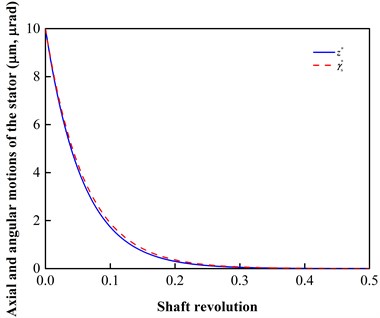
Fig. 7Comparison of critical transverse moment of inertia at different shaft speeds ω from 300 to 700 r/min (Λ from 2.5233 to 5.8878), and “relaxation region” offers a softer demand of angular stability when considering the slip flow
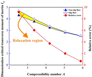
In the axial mode, it is clear that the axial damping coefficient shown in Fig. 5 never becomes negative over the range of from 2.5233 to 5.8878 or over the excessively wide range of from 0.5 to 50. Therefore, the stability of the gas face seal in the axial mode is not a significant factor to be focused on. However, the gas film coefficients shown in Fig. 5 can satisfy Eq. (24), and thus the angular stability of the gas face seal should be analyzed. Fig. 7 displays the dimensionless critical transverse moment of inertia as increases from 300 to 700 r/min. It can be seen that the critical transverse moment of inertia is greater under the slip flow condition, and that the relative error decreases as increases. Here, the deviation is marked in yellow and is called “relaxation region”. When the ratio of the real transverse moment of inertia to the critical transverse moment of inertia is larger than 1, the face seal is known to exceed its critical speed, indicating that an instability appears in the angular modes. Therefore, for a specific safety threshold (i.e., less than 1), the engineers are provided with an extra relaxation region for the stator design (in terms of the mass, the transverse moment of inertia and the geometry) to satisfy the demand for angular stability when considering the slip flow under low-parameter conditions. This advantageous effect under the slip flow condition is caused by the relative large linearized stiffness and damping coefficients of the gas film under the slip flow condition, which are related to the reduced central film thickness at equilibrium under the slip flow condition. Therefore, these successional phenomena essentially occur because of the loss of the viscous pumping due to the slippage at the solid boundary.
3.3. Tracking
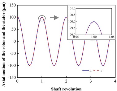
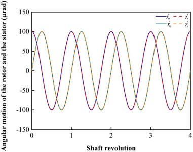
Fig. 8 displays a tracking example where the rotor has a periodic vibration with 100 μm, 100 μrad and 300 r/min (i.e., 2.5233). In the case, the slip flow is considered. The stator tracks the rotor in the axial and angular modes. In the close look of Fig. 8(a), the vibration amplitude of the stator is reduced, and a phase difference occurs between the mated rings. These phenomena also exist in the angular modes in Fig. 8(b).
Fig. 8Tracking example where Arz*= 100 μm, Arγ*= 100 μrad, ω= 300 r/min (i.e., Λ = 2.5233) and the slip flow is considered: a) axial motion; b) angular motions
a)
b)
Fig. 9 shows the axial and angular relative transmissibility at different shaft speeds ranging from 300 to 700 r/min (i.e., ranges from 2.5233 to 5.8878). The relative transmissibility increases with an increase in shaft speed, indicating that the tracking property worsens as increases. Moreover, it is obvious that the relative transmissibility is smaller under the slip flow condition. A reasonable explanation is that the slippage phenomenon will induce relative large linearized gas film coefficients which help to transmit the rotor motion to the stator. As the red curves show, this acceleration decreases as the slip flow diminishes. However, this advantageous effect of the slip flow on the tracking property should be doubted because the transmissibility is a ratio that used to only reflect the message about the amplitude rather than about the datum line. Namely, the improved tracking property under the slip flow condition is caused by the relative large linearized gas film coefficients under the slip flow condition, which are related to the decreased central film thickness at equilibrium under the slip flow condition. Although the tracking ability is better under the slip flow condition, the space for tracking motions has been compressed because of the decreased central film thickness at equilibrium. Therefore, an index including both “amplitude” and “datum line” is required. The critical ambient-disturbance amplitude, above which the seal will have face contact, are provided based on the transmissibility to cover the defect of transmissibility in characterizing the tracking property.
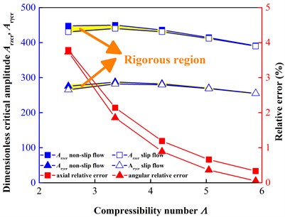
In engineering projects, the axial endplay and the angular wobble occur simultaneously. In Fig. 10, single axial-endplay and single angular-wobble situations are discussed respectively. The critical amplitude is smaller under the slip flow condition. It means that if an engineer ignored the slip flow and then selected a value in the “rigorous region” marked in yellow as a design criterion, face contact would occur. Therefore, the slip flow makes gas face seals require more conservative design and more rigorous manufacture and assembly for a non-contacting tracking. This disadvantageous conclusion drawn from the critical amplitude is in contrast with the advantageous conclusion obtained by the transmissibility, because the former considers the tracking property more comprehensively by adding the space for tracking motions. In addition, with the increase of , and vary non-monotonously. It is because the critical amplitude is a function of the central film thickness at equilibrium (Fig. 3) and the relative transmissibility (Fig. 9).
Fig. 9Comparison of relative transmissibility at different shaft speeds ω from 300 to 700 r/min (Λ from 2.5233 to 5.8878)
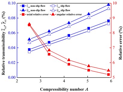
Fig. 10Comparison of critical amplitudes of axial endplay and angular wobble for face contact at different shaft speeds ω from 300 to 700 r/min (Λ from 2.5233 to 5.8878), and “rigorous region” requires more rigorous working conditions when considering the slip flow
4. Conclusions
The dynamics of a spiral groove gas face seal are established and the Boltzmann-Reynolds model with Fukui-Kaneko approximation is used to account for slip flow. Transmissibility in the step jump method is introduced into the perturbation method to characterize the tracking property. Based on the transmissibility, the critical amplitudes of axial endplay and angular wobble, above which the seal will have face contact, are provided to cover the defect of transmissibility in characterizing the tracking property.
The effect of slip flow on the stability and tracking properties of a spiral groove gas face seal under low-parameter conditions is researched. The results show that slip flow will induce a decreased central film thickness at equilibrium, a reduced load carrying capacity and a higher lift-off speed (i.e., a longer startup operation and more severe face wear). The decreased central film thickness induces to relative large linearized gas film characteristics that affect the stability and tracking. Unlike the axial stability, the angular stability should be focused on. Slip flow will induce an extra “relaxation region” in the critical transverse moment of inertia to provide a softer demand for angular stability. With regard to the transmissibility, slip flow will induce an advantageous effect on transmitting the rotor motion to the stator. However, after introducing the space for tracking motions, the results of the critical amplitudes of the axial endplay and the angular wobble show that slip flow will induce an extra “rigorous region” to make gas face seals require more conservative design and more rigorous manufacture and assembly for a non-contacting tracking. The proposition of “relaxation region” and “rigorous region” demonstrates the necessity of considering slip-flow under the low-parameter applications of gas face seals.
References
-
Huang W., Lin Y., Liu Y., Liu X., Gao Z., Wang Y. Face rub-impact monitoring of a dry gas seal using acoustic emission. Tribology Letters, Vol. 52, Issue 2, 2013, p. 253-259.
-
Huang W., Lin Y., Gao Z., Fan W., Suo S. An acoustic emission study on the starting and stopping processes of a dry gas seal for pumps. Tribology Letters, Vol. 49, Issue 2, 2013, p. 379-384.
-
Hu S., Huang W., Liu X., Wang Y. A fluctuation transient response analysis of spiral groove gas face seals. STLE Tribology Frontiers Conference, Chicago, USA, 2014, p. 41.
-
Hu S., Huang W., Liu X., Wang Y. Numerical model for dynamic behavior of spiral groove gas face seals using fractal contact model. 70th STLE Annual Meeting, Dallas, USA, 2015, p. 150.
-
Sayed M., Hamed Y. S. Stability analysis and response of nonlinear rotor-seal system. Journal of Vibroengineering, Vol. 16, Issue 8, 2014, p. 4152-4170.
-
Soltani M., Keshmiri M., Misra A. K. Dynamic analysis and trajectory tracking of a tethered space robot. ACTA Astronautica, Vol. 128, 2016, p. 335-342.
-
Shapiro W., Colsher R. Steady-state and dynamic analysis of a jet engine, gas lubricated shaft seal. ASLE Transactions, Vol. 17, Issue 3, 1974, p. 190-200.
-
Green I., Barnsby R. M. A simultaneous numerical solution for the lubrication and dynamic stability of noncontacting gas face seals. Journal of Tribology, Vol. 123, Issue 2, 2000, p. 388-394.
-
Miller B. A., Green I. Numerical formulation for the dynamic analysis of spiral-grooved gas face seal. Journal of Tribology, Vol. 123, Issue 2, 2000, p. 395-403.
-
Green I., Barnsby R. M. A parametric analysis of the transient forced response of noncontacting coned-face gas seals. Journal of Tribology, Vol. 124, Issue 1, 2002, p. 151-157.
-
Green I. A transient dynamic analysis of mechanical seals including asperity contact and face deformation. Tribology Transactions, Vol. 45, Issue 3, 2002, p. 284-293.
-
Zirkelback N., Andres L. S. Effect of frequency excitation on force coefficients of spiral groove gas seals. Journal of Tribology, Vol. 121, Issue 4, 1999, p. 853-863.
-
Zirkelback N. Parametric study of spiral groove gas face seals. Tribology Transactions, Vol. 43, Issue 2, 2000, p. 337-343.
-
Ruan B. A semi-analytical solution to the dynamic tracking of non-contacting gas face seals. Journal of Tribology, Vol. 124, Issue 1, 2002, p. 196-202.
-
Elrod H. G., McCave J. T., Chu T. Y. Determination of gas-bearing stability by response to a step-jump. Journal of Lubrication Technology, Vol. 89, Issue 4, 1967, p. 493-498.
-
Miller B. A., Green I. Numerical techniques for computing rotordynamic properties of mechanical gas face seals. Journal of Tribology, Vol. 124, Issue 4, 2002, p. 755-761.
-
Miller B. A., Green I. Semi-analytical dynamic analysis of spiral-grooved mechanical gas face seals. Journal of Tribology, Vol. 125, Issue 2, 2003, p. 403-413.
-
Ruan B. Finite element analysis of the spiral groove gas face seal at the slow speed and the low pressure conditions-slip flow consideration. Tribology Transactions, Vol. 43, Issue 3, 2000, p. 411-418.
-
Burgdorfer A. The Influence of the Molecular Mean Free Path on the Performance of Hydrodynamic Gas Lubricated Bearings. AECU-3771, I-A2049-2, Franklin Institute, Philadelphia, 1958.
-
Hsia Y. T., Domoto G. A. An experimental investigation of molecular rarefaction effects in gas lubricated bearings at ultra-low clearances. Journal of Lubrication Technology, Vol. 105, Issue 1, 1983, p. 120-130.
-
Mitsuya Y. Modified Reynolds equation for ultra-thin film gas lubrication using 1.5-order slip-flow model and considering surface accommodation coefficient. Journal of Tribology, Vol. 115, Issue 2, 1993, p. 289-294.
-
Fukui S., Kaneko R. Analysis of ultra-thin gas film lubrication based on linearized Boltzmann equation: first report-derivation of a generalized lubrication equation including thermal creep flow. Journal of Tribology, Vol. 110, Issue 2, 1988, p. 253-261.
-
Fukui S., Kaneko R. A database for interpolation of Poiseuille flow rates for high Knudsen number lubrication problems. Journal of Tribology, Vol. 112, Issue 1, 1990, p. 78-83.
-
Pecht G. G., Netzel J. P. Design and application of non-contacting gas lubricated seals for slow speed services. Lubrication Engineering, Vol. 55, Issue 7, 1999, p. 20-25.
-
Ruan B. Numerical modeling of dynamic sealing behaviors of spiral groove gas face seals. Journal of Tribology, Vol. 124, Issue 1, 2002, p. 186-195.
-
Green I., Etsion I. Stability threshold and steady-state response of non-contacting coned-face seals. ASLE Transaction, Vol. 28, Issue 4, 1985, p. 449-460.
-
Malanoski S. B., Pan C. H. T. The static and dynamic characteristics of the spiral-grooved thrust bearing. Journal of Basic Engineering, Vol. 87, Issue 3, 1965, p. 547-558.
-
Wilcock D. F, Bjerklie J., Cheng H. Design of floated shoe close clearance seals for supersonic jet engine compressors. Journal of Lubrication Technology, Vol. 90, Issue 2, 1968, p. 500-509.
Cited by
About this article

This work was supported by the National Key Basic Research Program of China (973) (Grant No. 2012CB026003), the National Science and Technology Major Project (Grant No. ZX06901), and the National Science and Technology Support Plan Projects (Grant No. 2015BAA08B02).
