Abstract
Particle damping is a kind of passive and strongly nonlinear damping for energy dissipation. Many researchers have expended huge amounts of effort and time to study internal mechanism of particle damping. However, there is not a systematic and feasible approach for estimating damping performance of non-obstructive particle damping (NOPD). In this paper, we performed studies to mathematically evaluate the damping effect of particle damping based on principles of gas-solid flows. In consideration of the structural characteristics of NOPD which granular materials should be filled into sealed cavity of vibrating structure and the damping act on lateral and bottom of holes in NOPD technology, the gross damping is divided into lateral damping and bottom damping by Janson's theory of stress change direction. And the damping coefficients are compiled into a plug-in by MATLAB and are invoked in FEM software by enterprise integration kits of COMSOL. Meanwhile the frequency domain and time domain analysis of the experiment are used to verify the prediction accuracy of dynamic vibration response of an aluminium cantilever beam which ONPD is imposed at the free end with different packing rate and granular material, the result indicate that the mathematical model has excellent performance to predict the dynamic vibration response of NOPD. Then, the relationship damping effect with the particle filling ratio, particle density and length-diameter ratio of the hole is also researched using co-simulation, it should be noted that larger packing rate and particle density, smaller length-diameter ratio of the hole can play excellent damping effects in NOPD.
1. Introduction
Particle damping technology is a new passive vibration control technology and derived from single impact damping technology. Due to favorable effects of vibration and noise control, simple structure, low-cost, smaller additional weight, easier to implement and suitable to harsh conditions, it is widely used in various industrial fields [1, 2]. The implementation of particle damping is grouped into two categorise, include particle damper (PD) technology and non-obstructive particles damping (NOPD) technology. PD technology only needs to attach PD damper on the surface of vibrating structure. But NOPD technology, the particles material should be filled in the cavity of vibrating structure similar to a counterbore. Because the appearance of the structure maintains original form as compared with PD technology, so engineer would rather employ NOPD technology to control structure vibration.
Non-obstructive particle damping is a strong non-linearity damping. Lots of experimental, analytical and numerical resources have been attempted to probe the damping mechanism. Looking through current literature, many researchers use the approach which look upon a bed of particles as a single particle to estimating the effect of particles damping [3-10]. The approach only deals with the damping roughly, but the internal mechanism is not investigated. Then, many researchers are inspired by particle dynamics simulation, also called Discrete Element Method (DEM), proposed by Cundall and Strack etc. [11]. By DEM, not only the parameters and properties of the single particle is researched, but also all particles could be studied in depth [12, 13]. It is very regrettable that the application is only limited to the Single-Degree-of-Freedom (SDOF) system or the equivalent SDOF and barely join to Finite Element Method. Therefore, it is necessary that equivalently establishing the numerical model and embedding it into finite element software to analyze the structural dynamic response in continuum structures.
Because non-obstructive particle damping is an application style of particle damping and similar to PD, and most of researchers equate NOPD with PD. M. Ben Romdhane equals the particle damping to an equivalent viscous damping base on the experimental method and establishes the corresponding model for discussing NOPD’s loss factor independently of the structure [14]. This numerical model only expressed vertical damping force which is imposed on the bottom of enclosure cavity, and ignores the effects of damping force at lateral. Guilhem Michon propose a honeycomb particle damping for space applications to enhance mission performance and replace classical hard particles with soft ones [15]. The same problem that damping force act at lateral is ignored.
More recently, our group originally developed a theoretical analysis model based on multiphase flow theory (MFT) of gas-particle, described carefully the mechanism of the energy dissipation, and damping mechanisms of inter-particle collisions and friction which is separately defined as equivalent viscous damping coefficient [16]. In the process of predicting the dynamic response of the continuum structures with PD damper, the prediction model attained good performance. Section 2 of this paper will gives a detailed introduction to the prediction model. In spite of the prediction model described particle damping accurately, it is not suitable for non-obstructive particle damping due to the equivalent viscous damping act on the bottom and lateral of the holes. This paper will discuss the method of damping distribution by Janson’s theory of stress change direction. In Section 3, the two parts damping are easily embedded in FEM software COMSOL. The predicting acclacation responses are comparing with experimental ones and verifying the validity of this model. Based on previous research, some characteristic parameters of non-obstructive particle damping in aluminum cantilever beam are more easily analyzed using co-simulation, includes packing ratio, particle density and diameter-length ratio of the hole. The result is described at Section 4. So, the researching result have great significance for guiding the design of complex structure with non-obstructive particle damping in engineering.
2. Basic theory
2.1. Numerical model
Recently, Wu et al. [16] have performed studies to mathematically evaluate the energy dissipation mechanisms of particle damping based on principles of gas-solid flows, and explored a numerical model that the damping mechanisms are separately defined as equivalent viscous damping coefficient. Fang and Tang [4] further carry out detailed studies about the quantitatively property of energy dissipation mechanisms with different packing ratios, various forced excitation levels, and enclosure dimensions. And researching results illustrate that the multiphase flow theory is a feasibility approach in evaluating the damping effect. Based on the theory, the equivalent viscous coefficient due to inter-particle collisions is defined as the following forms [17]:
where is the radial distribution function, can be expressed as:
where, is fluctuation parameter, is the packing ratio defined as the volume of particles to the total volume of the cavity, and is the density and the mean diameter of particles respectively, d is the diameter of the cavity and h is the height of the cavity, is the restitution coefficient of the particle.
The equivalent viscous coefficient due to friction is defined as the following forms [17]:
where is the angle of internal friction, is the second invariant of the deviatoric stress and is constant which depends from the particle property.
Thus, viscous damping force can be formulated as:
where, , , is the equivalent volume density of the mixture flow related to the densities of the gas, is the cross-sectional area of the hole, is the frequency, is the diameter of the cavity
So, the equivalent damping coefficient due to inter-particle collisions is defined as the following forms:
where:
with:
The equivalent damping coefficient due to friction is defined as the following forms:
So, the particle damping due to inter-particle collisions and friction is defined as:
These formulas described the derivation process of gross damping due to inter-particle collisions and friction, the final numerical model reveal the internal mechanism of particle damping. But it can’t be directly applied to predict dynamic response because damping force act on many boundary conditions. So, the distribution of damping force must be discussed in NOPD technology.
2.2. The distribution of damping
It is obvious difference between NOPD technology and PD technology, PD technology will attach PD damper on the surface of structure, and damping force act on the contact surface between PD damper and structure. But NOPD technology need to fill the particles in the cavity of vibrating structure, the damping force act on the bottom and lateral of cavity. After consulting literature material, we found the moving barn is similar to vibrating particles inspired by Janson's theory of stress change direction [18, 19].
Fig. 1Pressure analysis model
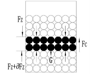
According to Janson’s theory of stress change direction, the gravity of the lower layer particle changes the direction partly by the gravity of upper layer particle and became to surface normal stress. But the forces loaded of the particle is a self-balanced system, as show in Fig. 1. According to force balance, equilibrium equations is established, and can be expressed as:
where, , , .
So, we can get the equation:
where, is the diameter of cavity; is the density of particles; is surface normal stress from the upper layer of particle gravity; is the shear stress from wall.
According to Jenson’s theory of Stress changed the direction, we can get the equation:
where, is Jenson’s coefficient, is coefficient of kinetic friction.
By some mathematical manipulation, we can obtain the forces loaded of the bottom and the lateral of hole:
The distribution coefficient of particle damping force as follow the forms:
From Eq. (20), it should be noted that the equivalent damping coefficient is divided into two parts, and applied in different boundary. This is an important guarantee to accurately predict dynamic response of NOPD structure by FEM software.
2.3. The dynamical equation
The particle damping technology is a passive mean for vibration suppression, the excellent damping effect is due to the excited particle act on vibrational structure and rely on vibration strength of continuum structure. If want to exactly predict dynamic response, it is necessary to link up particle with continuum structure and establish dynamical equation to express the relation. The damping of the whole system contains two parts: the structure damping of the continuum structure and equivalent damping of particles. The dynamical equation should be expressed as follows:
where is the sum of the masses of the primary system and granular material, is stiffness of system, is harmonic excitation is the structure damping, is the equivalent damping of particles.
In NOPD technology, the particle damping act on the lateral and the bottom of the holes, gross damping force should be divided into two parts. By some mathematical manipulation with the distribution coefficient, the dynamical equation is evolving to this form as follows:
COMSOL Multiphysics is a programmable FEM software, users might compile some plug-in programs according to own requirements. So, we can compile the two parts equivalent damping to M file separately by Eqs. (1-20), and call it into COMSOL by the function of COMSOL with MATLAB. Then the two parts equivalent damping can be added to corresponding boundary conditions for predicting the dynamic response of the continuum structure accurately.
3. The experimental verification
The previous section explored numerical model about NOPD. Whether the improved model can accurately predict the damping effect, it should be validated by experiment. So, we designed an experiment platform for measuring dynamic response of continuum structural.
In this paper, we choose an aluminum alloy beam as research object, the reason is that it is an infinite DOF system and similar to the structure of engineering application as opposed to the single DOF systems in the literature [20, 21]. The beam dimensions are: length 1 m, width 0.04 m and height 0.015 m, Young’s modulus 67 GPa, density 2750 kg/m3. In order to measure damping effect of particles, four Cylinder holes are drilled at the end of beam due to the part of beam is in excessive vibrating state, and the position is located at first five modal top (the extreme displacement values of modal shape).
Fig. 2Schematic of the experimental apparatus for free vibration
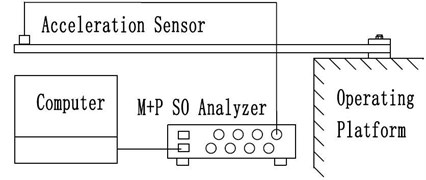
The verified experiment contains two parts: free vibration in time domain analysis and forced vibration in the averaged frequency transformation. At first, the free vibration is presented. The experimental equipment and connection is shown in Fig. 2, it is consisted of the cantilever beam, acceleration transducer (Dytran3133B1) for measuring the accelerations responses in time domain and Dynamic Signal Analyzer (M+P SO Analyzer) for collecting and processing the signals.
Fig. 3Free vibration of the beam with different mass packing ration: a) packing ratio 40 %; b) packing ratio 80 %
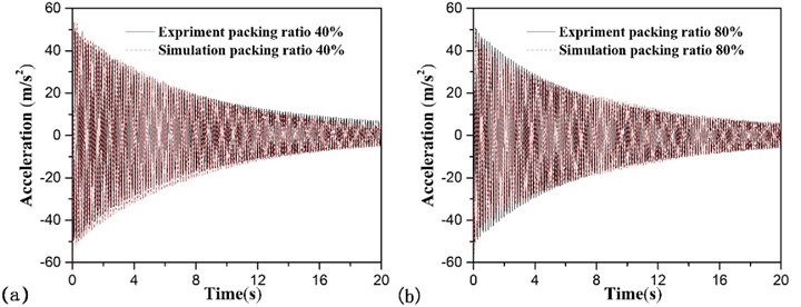
In this part, we take tungsten powder as filler, the density is 17000 kg/m3, and the equivalent diameter of particles is 0.3 mm, the restitution coefficient of particles is 0.6, the kinetic friction coefficients between the individual particle and between the particles and the wall of the hole are 0.3 and 0.2 respectively. After data processing, the numerical results and experimental ones is showed in Fig. 3. We can found that the two group data are consistent and prove the accuracy of numerical model preliminarily.
To further prove the accuracy of numerical model, we adopt forced vibration in the averaged frequency transformation to research it. The experimental equipment and connection as shown in Fig. 4, the experimental model is consisted of the cantilever beam which was attached to a Smart Shaker (MTK2004E01) with a simple harmonic excitation force by the amplifier, the accelerations responses and excitation force were measured with the force sensor (Dytran1051V4) and acceleration transducer (Dytran3133B1), the signals are collected and processed by a Dynamic Signal Analyzer (M+P SO Analyzer).
The developed experiment platform can be used for measuring the dynamic response of non-obstructive particle damping in the continuum structure and recording the evolutions of force and acceleration of the infinite DOF system. In order to ensure measurement accuracy, the frequency step of simple harmonic excitation force should be much less than first order natural frequency (8 Hz). So, it is defined as 1 Hz, the test results are described in the frequency response functions (FRF). In this part, we choose multipoint collecting method to research the frequency response functions (FRF). There are six points to be resided on a different modal node and modal top. The position of each sampling point shown in Fig. 5.
Fig. 4Schematic of the experimental apparatus for forced vibration
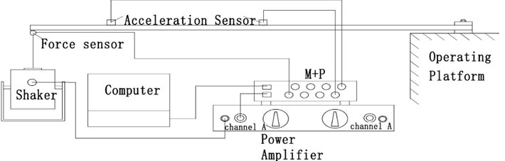
Fig. 5Experimental object: a) the physical map of NOPD holes; b) Riding position of the NOPD holes and the data collecting site on the beam
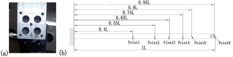
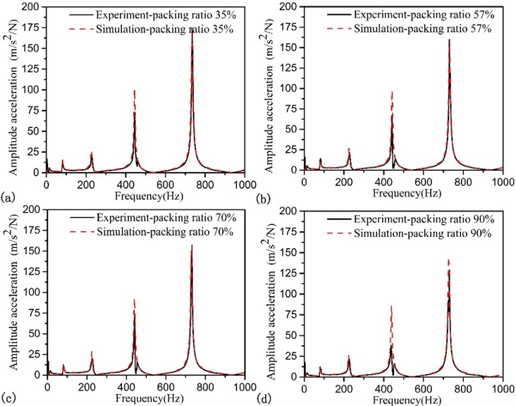
Fig. 6FRFs of the beam with different mass packing ration, monitoring sets is located at point 6 and exciting force is placed at point 6: a) packing ratio 35 %; b) packing ratio 57 %; c) packing ratio 80 %; d) packing ratio 90 %
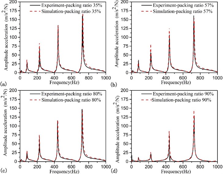
Fig. 7FRFs of the beam with different mass packing ration, monitoring sets is located at point 4 and exciting force is placed at point 6: a) packing ratio 70 %; b) packing ratio 90 %
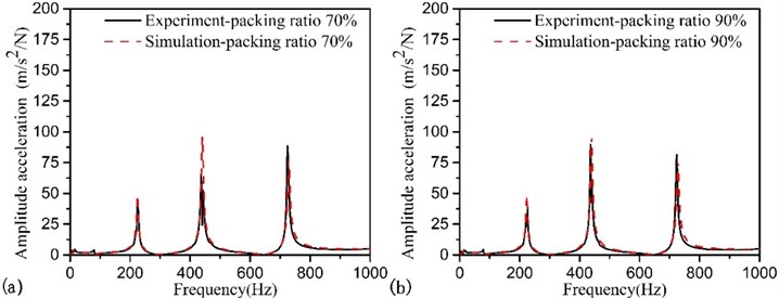
Fig. 8FRFs of the beam with different mass packing ration, monitoring sets is located at point 5 and exciting force is placed at point 6: a) packing ratio 35 %; b) packing ratio 57 %; c) packing ratio 80 %; d) packing ratio 90 %
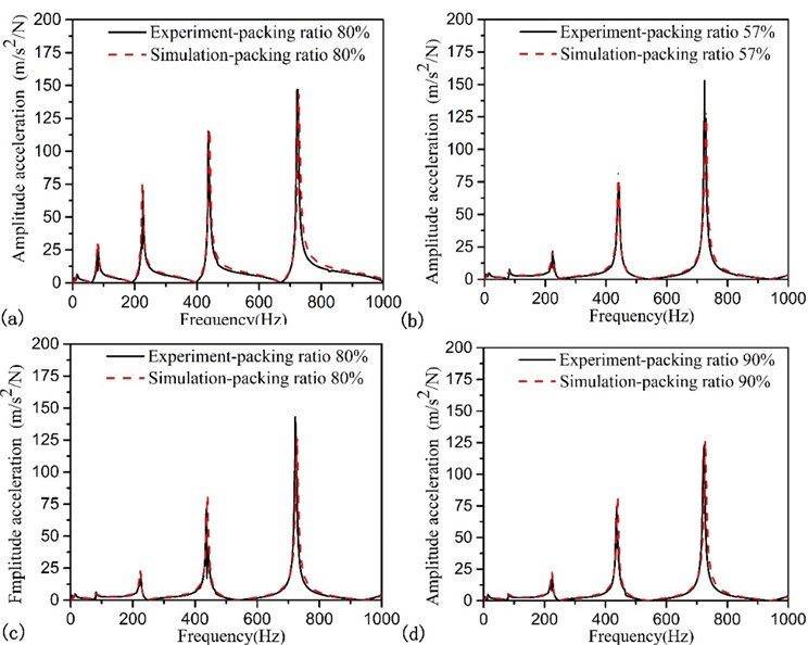
At the first, we verify the prediction model about the different granular filling ratio. The exciting force is placed at point 6 under the beam bottom. The filler is still tungsten powder. When monitoring sites located at point 6, the FRF is shown in Fig. 6 with different packing ratio. And we can see that numerical results are consistent with experimental ones. To further verify the accuracy, monitoring sites located at point 4 and point 5, the FRF is independently shown in Fig. 7 and Fig. 8 with different packing ratio.
At the same time, we change the position of exciting force and locate it at point 5, the acceleration dynamic response is shown in Fig. 9, the picture shows the same answer that it is a practical model to predict the responses of accelerations.
The damping effect is linked closely with different material; different material will present different damping performance. So, we studied the acceleration dynamic response with different particle materials. The particle is made of steel ball whose density is 7858 kg/m3, and the diameter of particles is increased from 0.3 mm to 1 mm. The restitution coefficient of particles is 0.55. The kinetic friction coefficients between the individual particle and between the particles and the wall of the hole are 0.4 and 0.35 respectively. When monitoring stations located at point 6 and the exciting force is placed at point 6 under the beam bottom, the FRF is shown in Fig. 10.
By the contrast the simulation results and testing data, we have confirmed the prediction models of non-obstructive particle damping that can accurately predict the acceleration dynamic response. So, we can utilize this method to guide non-obstructive particle damping application in engineering.
Fig. 9FRFs of the beam with different mass packing ration, monitoring sets is located at point 6 and exciting force is placed at point 5: a) packing ratio 35 %; b) packing ratio 57 %; c) packing ratio70 %; d) packing ratio 90 %
4. The analysis of the particle damping characteristic parameters
The previous experiments have confirmed that numerical model can accurately predict the dynamic response of particle damping. So, we use the developed model to analyzed the influence of characteristic parameters of particle damping to structure dynamic response, the research object is still cantilever beam.
Particle damping is a pragmatic vibration control technology. Engineers pay close attention to vibration damping effect, how to achieve satisfactory damping effect with small amount of particles is a hot topic. So, illustrating the relationship of damping effect to particle and cavity is conducive to solve the problem. In this paper, we take acceleration decrease amplitude and acceleration decrease amplitude per unit weight of particles to express the trend of damping effect. These two expression equation is as follows:
where, is decrease amplitude, is decrease amplitude per unit weight of particles, is th order formant without particles, is th order formant with particles, is added mass.
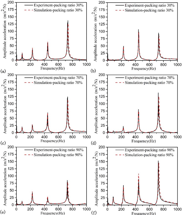
Fig. 10FRFs of the beam with different mass packing ration, exciting force is placed at point 6: a) packing ratio 30 %, monitoring sets is located at point 1; b) packing ratio 30 %, monitoring sets is located at point 4; c) packing ratio70 %, monitoring sets is located at point 2; d) packing ratio 70 %, monitoring sets is located at point 5; e) packing ratio 90 %, monitoring sets is located at point 3; f) packing ratio 90 %, monitoring sets is located at point 6
4.1. The granular filling ratio
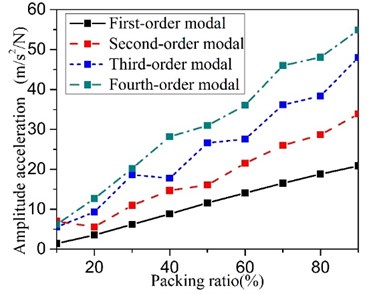
The efficiency of particle damping is closely related to the granular filler in number. With a large amount of granular, the energy dissipation will be improved in number. But how change trend of damping effect by packing ratio? This paper will illustrate the phenomenon by the co-simulation method. In this part, the particle is made of tungsten powder whose density is 17000 kg/m3, and the equivalent diameter of particles is 0.3 mm. The results as shown in Fig. 11. Researches show that damping effect is proportional to the particle filling ratio, and damping effect per unit weight of particles is basically a constant. If we want to get better damping effect with small amount of packing space, please choose larger filling ratio.
Fig. 11The granular filling ratio influence on the effect of the particle damping
4.2. Particle density
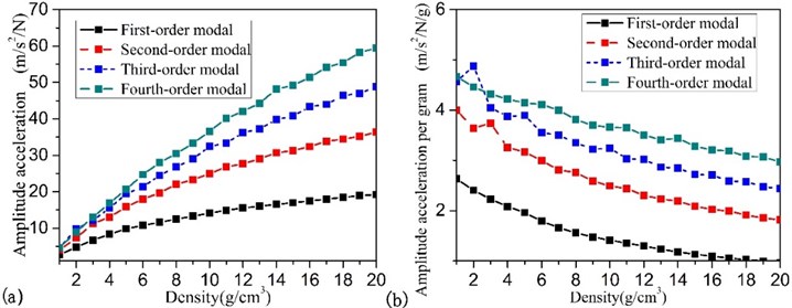
Particle density is an important parameter of the particle damping. It will influence surface contact stresses and inertia force of particle, further influence damping effect. In this part, the change trend of damping effect by particle density will be investigated. In order to ensure the comparability of research result, the simulation study is carried out with unification filling ratio and packing space of cavity, the diameter of particles is 0.3 mm and the filling ratio of particles is 90 %. This study result shows in Fig. 12. We can found these changing trends of the damping effect and the damping effect per unit weight of particles is inconsistent. So, we want to achieve good preference in small space, high particle density is the preferred choice.
Fig. 12Particle density influence on the effect of the particle damping: a) the amount of the vibration reduction, b) the vibration reduction per unit weight of particles
4.3. The diameter-length ratio of the hole
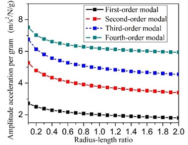
Particle damping effect is due to collision and friction. Energy wasted due to friction . If become aggravated, either for intensifies the rotation or intensifies vertical motion of particle, energy dissipation become more intense [22]. When the numerical mode is verifyed (1mm steel ball), we found that the rotation speed of steel ball nearby cavity lateral is more severe than cavity center. In reaction to the phenomenon, we think that the larger flank area of cylinder will improve damping effect. So, the diameter-length ratio of the hole will be an important parameter and is worth to research by the co-simulation technology. In order to ensure the comparability of data, holes’s volume and the granular filling ratio and mass is constant. The output optimization results confirmed my idea and the detail as shown in Fig. 13. If primary system with particle damping wants to get better effect, the lesser diameter-length ratio is optimally choice.
Fig. 13The diameter-length ratio influence on the effect of the particle damping
5. Conclusions
The work which is reported in this paper aims at guiding the application of NOPD technology in engineering. For predicting the dynamic response of continuum structure with particle damping, we have developed a numerical model to evaluate the damping mechanism of particle damping base on the gas-solid two-phase flow theory. In order to apply it into NOPD technology, the equivalent damping is divide into two parts: bottom damping and lateral damping, and be imposed to corresponding boundary conditions. At the same time, the acceleration dynamic responses that were obtained by the predicting methods are compared with experimental ones corresponding and verify the validity of this mode. For improving the application effect, the changed trend of damping effect by the particle filling ratio, particle density and length-diameter ratio of the hole are analyzed by co-simulation method. These changed trend will constitute a data base to guide engineering applications of NOPD technology.
While this article proposed theory can accurately estimate the particle damping effect in the continuum structure. But simulation error still exists. In the future research, the precision of the model will be improved for more accurate estimates of particle damping dynamic response in the continuum.
References
-
Panossian H. V. Structural damping enhancement via non-obstructive particle damping technique. ASME, Transactions, Journal of Vibration and Acoustics, Vol. 114, 1992, p. 101-105.
-
Simonian S. Particle damping applications for shock and acoustic environment attenuation. Proceedings of the 49th AIAA/ASME/ASCE/AHS/ASC Structure, Structural Dynamics and Materials Conference, 2008.
-
Friend R. D., Kinra V. K. Particle impact damping. Journal of Sound and Vibration, Vol. 233, 2000, p. 93-118.
-
Salueña C., Pöschel T., Esipov S. E. Dissipative properties of vibrated granular materials. Physical Review E, Vol. 59, 1999, p. 4422-4425.
-
Masanobu I. Effectiveness of the particle damper with granular materials. 3rd International Conference on Integrity, Reliability and Failure, Porto, Portugal, 2009.
-
Isao Y., Yoshito T., So N. Y. Particle damping with granular materials for multi-body system. ICSV 15 International Congress on Sound and Vibration, Daejeon, Korea, 2008.
-
Trigui M. An experimental study of a multi-particle impact damper. Proceedings of the Institution of Mechanical Engineers, Part C: Journal of Mechanical Engineering Science, Vol. 223, 2009, p. 2029-2038.
-
Mao K. M. Simulation and characterization of particle damping in transient vibrations. Journal of Vibration and Acoustics, Vol. 126, 2004, p. 202-211.
-
Lu Z., Lu X., Masri S. F. Studies of the performance of particle dampers under dynamic loads. Journal of Sound and Vibration, Vol. 329, 2010, p. 5415-5433.
-
McNamara Sean, Young W. R. Inelastic collapse in two dimensions. Physical Review E, Vol. 50, Issue 1, 1994.
-
Cundall P. A., Strack O. D. L. A discrete numerical model for granular assemblies. Geotechnique, Vol. 29, 1979, p. 47-65.
-
Zhang C., Chen T. N., Wang X. P. Discrete element method model and damping performance of bean bag dampers. Journal of Sound and Vibration, Vol. 333, 2014, p. 6024-6037.
-
Mao K. M., Wang M. Y., Xu Z. DEM simulation of particle damping. Powder Technology, Vol. 142, 2004, p. 154-65.
-
Romdhane Ben M., Bouhaddi N., Trigui M. The loss factor experimental characterization of the non-obstructive particles damping approach. Mechanical Systems and Signal Processing, Vol. 38, 2013, p. 585-600.
-
Michon G., Almajid A., Aridon G. Soft hollow particle damping identification in honeycomb structures. Journal of Sound and Vibration, Vol. 332, 2013, p. 536-544.
-
Wu C. J., Liao W. H., Wang M. Y. Modeling of granular particle damping using multiphase flow theory of gas-particle. Journal of Vibration and Acoustics, Vol. 126, 2004, p. 196-203.
-
Fan L. S., Zhu C. Principles of Gas-Solid Flows. Cambridge University Press, Cambridge, 1998.
-
Jia L., Qingfan S., Xuanwen L. Size dependence of effective mass in granular column. Physica A, Vol. 388, 2009, p. 379-391.
-
BRauer K., Pfitzner M., Krimer D. O. Granular elasticity: stress distributions in solid and under point loads. Physical Review E, Vol. 74, 2006, p. 061311.
-
Chen T. Dissipation mechanisms of non-obstructive particle damping using discrete element method. Proceedings of SPIE International Symposium on Smart Structures and Materials. Newport, California, 2001, p. 294-301.
-
Friend R. D., Kinra V. K. Particle impact damping. Journal of Sound and Vibration, Vol. 233, Issue 1, 2000, p. 93-118.
-
Sánchez Martín, Rosenthal Gustavo, Pugnaloni Luis A. Universal response of optimal granular damping devices. Journal of Sound and Vibration, Vol. 331, Issue 20, 2012, p. 4389-4394.
Cited by
About this article

The work described in this paper was supported by NSFC (Natural Science Foundation of China) Project No. 51075316 and Program for Changjiang Scholars and Innovative Research Team in University (PCSIRT) No. IRT1172.
