Abstract
Work is aimed at the study of a rotor with a vertical axis and a fixed ball-type automatic balancer, whose body is placed concentrically in relation to the rotation axis. The rotor has disbalance that creates vibrations of the system. An automatic balancer with a torus-shaped body contains one ball-type corrective mass that freely rolls within the body of the automatic balancer both circle-wise and in cross-section. This reduces forces of resistance in the motion regime of a ball to the minimum, but simultaneously decreases the chance of putting the automatic balancer in motion. Experimental researches with the automatic balancer have proved that together with the working regime, when a ball stops in relation to the rotating body towards disbalance, there is a regime when a ball continuously moves in relation to the body of the balancer. A mathematical model containing four differential equations has been made for a rotor with an automatic balancer. The results of the calculations have shown that a ball of a balancer with a torus-shaped body has at least two motion regimes, one of which is a working regime, while another one is superfluous one.
1. Introduction
In order to develop constructions with higher quality it is necessary to decrease vibrations of the rotor. Vibrations of the rotor system are to be decreased both in the stable regime and in other motion regimes. Automatic balancers with balls, liquid etc. can be named among the devices that are able to decrease vibrations of a rotor.
If a ball takes up an optimal place in the body of a balancer, which is possible at a friction force decreased to the minimum, then the performance of the automatic balancer will be most efficient. This is possible if a ball has only one contact point with the body’s surface. Then the body of the automatic balancer has to be torus-shaped with a circular cross-section. Experimental researches with real automatic balancing devices with a vertical rotation axis have shown that balls have various motion regimes when a rotor rolls with working speed. In the balancing regime balls stop in relation to the balancer’s body towards disbalance [1]. In the second regime balls steadily and continuously move in relation to the body of the balancer, and vibrations of the rotor increase. The case of continuous movement of the ball has been experimentally studied in the research of a centrifuge [2] and in the research of the mathematical model of the automatic balancer [3]. In order to provide a working regime for the automatic balancer, there has been a construction received experimentally [4], in which only working regime has been realized, i.e. during rotor’s rotation the balls stop in relation to the body against disbalance.
2. Experimental researches
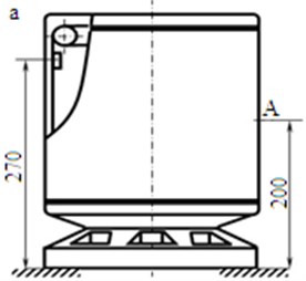
The scheme of the experimental centrifuge and the amplitudes of the body’s vibrations in two motion regimes of the balls can be seen in Fig. 1 [2]. Rotor disbalance has been imitated with mass of 50 g, which has been attached to the centrifuge container. It has been attached at the distance of 270 mm from the base and the body’s vibrations have been measured in point A at the distance of 200 mm from the base (Fig. 1(a)). The rotor of the centrifuge rotates with the angular speed 140 s-1.
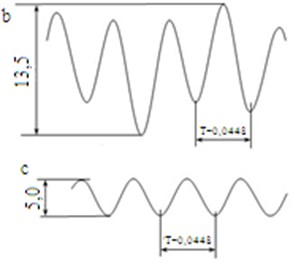
The experimental research of the ball-type automatic balancer with vertical rotation axis shows that the balancer has various working regimes. In one regime balls steadily and continuously move in relation to the body of the balancer and this results in the increase of vibrations in the body of the centrifuge (Fig. 1(b)).
In the second regime the balls stop in relation to the body of the balancer motionlessly towards disbalance and this is a balancing regime. Vibrations of the body of the centrifuge decrease in this case (Fig. 1(c)).
Fig. 1a) Scheme of the experimental centrifuge; amplitudes of body’s vibrations in point A in two regimes: b) in case of the relative motion of the ball; c) – in case of automatic balancing (T= 0,0448 s-1 – rotation period)
3. Numerical scheme and mathematical model of the ball-type balancer
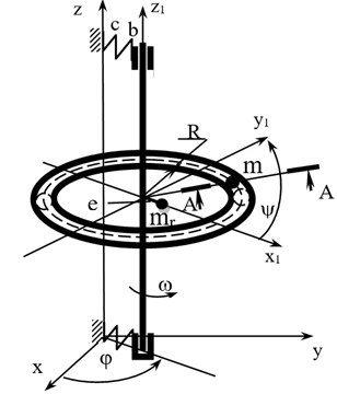
This work is aimed at the study of a symmetric, vertical tough rotor that is fixed in bearings, with an ability to move in the space. The body of the balancer is torus-shaped; there is a ball with mass m inside it. The rotor with mass has disbalance with value . The rotor is fixed to the base with flexible system, which has toughness coefficient c and dissipation coefficient . A numerical scheme of the rotor with four free stages is shown in Fig. 2.
Fig. 2Numerical scheme of the rotor
Differential motion equations in the rotor systems with the automatic balancer, according to the numerical scheme, are as follows:
The standing point of the corrective mass (ball) is determined by two coordinates and in a system of moving coordinates, which is connected to the rotor and rotate with angular speed .
The rotor rotates with constant angular speed 140 s-1. Taking into account that in the stationary regime the oscillations in the rotor axis are approaching disbalance , let us simplify the Eq. (1-4). In addition, we will exclude the ball’s accelerators from them to make it possible to calculate the model with the help of SPRING software [5]:
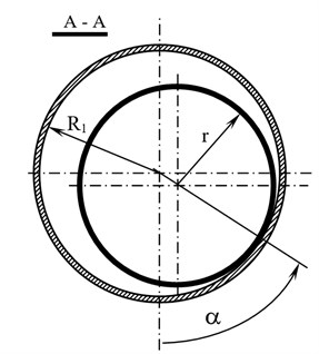
where: – mass of the rotor system; – angle of the rotor’s turning around its axis, rad; 9,81 m/s2 – acceleration of a free drop; – rotor disbalance; – specific normal speed of the ball on the surface of the balancer, m/s2 (Eq. (9)); – angle determining the condition of the mass centre of the corrective mass in relation to the straight line that unites the rotor’s axis with the balancer’s body in the direction of the axis rotation; – angle determining the condition of the mass centre of the corrective mass in the cross-section in relation to the vertical axis that goes through the centre of the body’s cross-section; – coefficient of the rotational friction between the rotation of the ball and balancer’s body and in the cross direction, m; – torus centre line radius, m; – torus cross-section radius, m; – radius of the ball, m; and:
4. Research and results of the mathematical model
Differential motion Eqs. (5-8), in the rotor systems with the automatic balancer have been researched with the help of SPRING software that enables calculating motion of the ball both in the working and superfluous regimes. The ball, which is found in the torus-shaped body of the automatic balancer, has various motion regimes during the rotor’s rotation. One of them is when the ball stops in relation to the body of the automatic balancer from the opposite side of disbalance on the torus side, i.e. 3,14156 and 1,56825 rad. We will call this type of the balls’ motion together with the body of the automatic balancer as the working regime. In this regime the force that works upon the ball is divided into two components. One force component works in the radial direction while another one in tangential. In the working regime the tangential component attempts to move the ball in the direction against rotor disbalance. At the same time, the closer the ball is to the place of the working regime ( 3,14156 rad), the less tangential force works upon the ball.
The regimes of the motion of the ball and the rotor have been researched with the following parametres of the rotor system: 0,2 m; 0,015 m; 0,0125 m; 0,005 m; 10 kg – mass of the rotor; 0,05 kg – mass of the ball; 10 N/m – toughness of the flexible system; 50 N·s/m – dissipation coefficient; 140 s-1 – angular speed of the rotor; 10-5 m – friction coefficient.
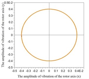
In the second motion regime of the ball the ball moves continuously in relation to the body of the automatic balancer both in the direction of the torus circle and in cross direction. We will call this type of the ball’s motion as a stable superfluous motion regime (Fig. 3, Fig. 4).
Fig. 3Phase portrait of the superfluous motion regime of the ball
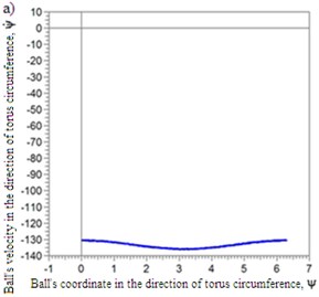
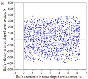
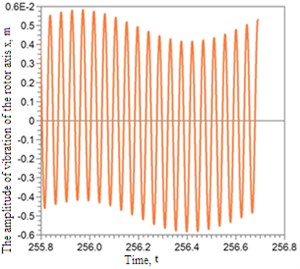
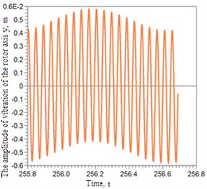
Fig. 4Axis amplitudes of the rotor
It can be seen in Fig. 5 that in the working regime the ball stops in the torus-shaped body in the direction of rotation 3,14156 rad, and in the cross direction on the body’s surface with coordinate 1,56825 rad.
Fig. 5Phase portrait of the ball’s working regime
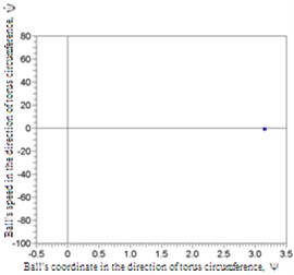
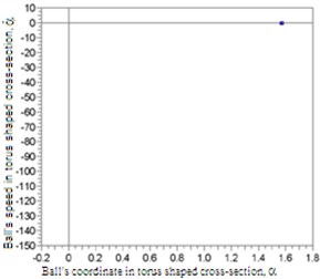
Fig. 6Amplitudes of vibrations of the rotor axis
At the same time the rotor axis reduces amplitudes of vibrations, which can be seen in Fig. 6.
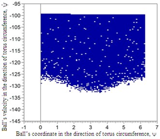
The dark area indicates that at initial conditions and (initial phase coordinates in cross-section 0 and 0) the working regime is provided for the balancer. If initial conditions and are taken outside the dark area (at 0 and 0) there will be the superfluous working regime of the ball in the balancer.
In order to find initial conditions at which the ball will enter the working regime, the graphs in the system of the ball’s phase coordinates have been built, Fig. 7.
Fig. 7Initial conditions according to phase’s coordinates ψ and ψ˙ when α= 0 and α˙= 0 with coefficient of friction: k= 10-5 m
5. Conclusions
The results of the calculations have shown that a ball in the torus-shaped balancer has at least two motion regimes, one of which is the working regime and another one is the superfluous regime. The rotor axis moves with increased amplitudes when the superfluous regime occurs. Superfluous regime is stable and to make the ball enter the working regime it is necessary to provide for initial conditions (initial speed and angle).
References
-
Rajalingham C., Bhat R. B., Rakheja S. Automatic balancing of flexible vertical rotors using a guided ball. International Journal of Mechanical Sciences, Vol. 40, Issue 9, 1998, p. 825-834.
-
Strautmanis Jurjevs, Griņevičs I. The influence of torus shaped autoequalizer on the vibration of rotary systems. The 9th International Conference on Mechatronic Systems and Materials, Vilnius, Lithuania, 2013.
-
Strautmanis G., Grinevich I., Strautmane V. The influence of automatic equalizer and rotor parameters on the ball’s motion mode. Mechatronic Systems and Materials, Opole University of Technology, Opole, Poland, 2014, p. 135-141.
-
Strautmanis G., Jurjevs V., Cokalo V. Veļas mazgājamo mašīnu centrifūgu balansēšanas ierīce. LV Patent LV14368B, P.V., P-11-57, 2011.
-
Ščukins I., Zakrževskis M., Ivanov Y., et al. Application of software SPRING and method of complete bifurcation groups for the bifurcation analysis of nonlinear dynamical system. Journal of Vibroengineering, Vol. 10, Issue 4, 2008, p. 510-518.
About this article

