Abstract
This paper compiles kinematic and dynamic models of the process of crushing grains, which allows specifying the required parameters of the cage mill and setting the optimal operating modes.
1. Introduction
High-performance and high-quality crushing can be provided by disintegrator with controlled operating mode (Fig. 1). Detailed description of such disintegrator is given in [1].
Fig. 1Structure chart of disintegrator with a controlled operating mode
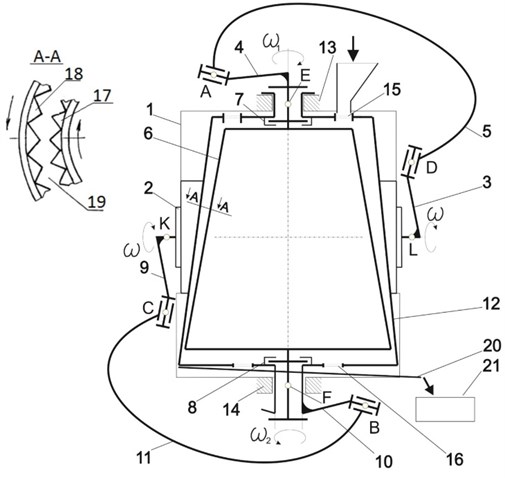
A main feature of this disintegrator is that Bennett’s parallelogram and antiparallelogram [2-4] are used as crushing cones drives. Design features of elements allow to convert uniform motion from driving crank into non-uniform motion of driven crank [5].
2. Kinematics of operating devices of disintegrator
Parameters of motion of driven cranks of Bennett’s parallelogram and antiparallelogram used as drives are the most important in kinematic model of operating devices – disintegrator cones [6]. Dependence of kinematic parameters of driven cranks on the law of motion (rotation angle) of the driving crank is:
As you can see, angle is unproportional to the angle . Differentiating of one of Eq. (1) allows to obtain the angular velocity [7]:
The expression shows that when – constant, the angular velocity of the crank is not constant and depends on the position of driving crank, i.e. the angle . In that case the maximum value of the absolute value of can be reached at = 0, and the minimum – at = 180°:
Then irregularity rotation factor of the driven crank can be evaluated as:
here it is assumed that .
By differentiating expression Eq. (4) in time, we obtain the angular acceleration of the driven crank:
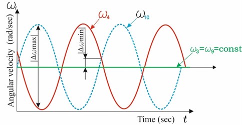
Analysis of obtained Eq. (2-5) shows that the motion of the driven crank is irregular (Fig. 2). This leads to the irregular motion of operating devices of disintegrator. As a result, dispersing and activation processes will be held in a environment with varying angular velocities, angular accelerations, i.e. more intensively.
Fig. 2Graph of variation of angular velocities of driving (3,9) and driven (4,10) cranks
We have developed a 3D model of the disintegrator in Solid Works system and conducted CAE – analysis of this model. This research has shown the validity of obtained theoretical equations of kinematics and 3D model as well.
The inner cone of disintegrator is driven through the Bennett’s parallelogram, and the outer cone is driven by the same electric motor which moves the Bennett’s antiparallelogram. As a result, (Fig. 2) uniform rotation of the motor shaft and driving cranks (3,9) leads to the irregular rotation of driven cranks (4,10). Since driving cranks are rotating in opposite directions, graph of angular velocities will take the form shown in Fig. 2. It is possible to change phases difference by changing the fixed positions of driving cranks 3,9 relative to each other.
Thus, the possibility of adjusting of differences of acceleration and deceleration phases of driven cranks gives the possibility to adjust dynamic parameters of disintegrator for different crushed materials.
3. Dynamics of crushing process
Preliminary study on ranking factors has shown that destroying effect of crushed materials under crushing impact depends on drive power, angular velocity and torque of driven cranks, mass and linear velocity of crushed material.
The kinetic energy of a grain of sand in the moment of impact is determined by the well-known formula [8]:
where – mass of grain of sand, – velocity of grain of sand.
Sand particles in disintegrator acquire significant kinetic energy, part of which transforms into the heat surface energy. Changing of kinetic energy of particles can be evaluated as:
Only a small part of the energy in disintegrator is helpfully consumed. A large part of it is spent on overcoming the friction between particles and surfaces of device and change of kinetic energy of materials. Such energy is finally released as heat. The value of destruction work can be evaluated as:
where – destructive force of grain of sand, – thickness of destroyed layer of grain of sand.
Forces occurring at crushing in disintegrator (Fig. 3) create a voltage, concentrated on microdefects of particles. Such voltages exceed the average value of destructive stress.
Fig. 3The scheme for preparation of a dynamic model of crushing process
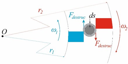
Upon reaching the local values of the voltage exceeding the tensile strength, cracks are starting to occur and grow, which leads to destruction of particles. Energy conditions of development cracks can be evaluated as:
By integrating both sides of Eq. (11), we obtain that:
where: and – moments of inertia of cones obtained by formula ; and – angular velocities of first and second cones; – the distance between the axis of the cone and grain of sand; – rotation angle of the cone.
The resulting model of dynamic process crushing of grains of sand in the two-degree of freedom conical disintegrator allows to solve the following tasks:
1) Identify the destructive power of crushing of a grain of sand under the condition that, , , and are given constructively, and is determined by empirical method (somewhere about = 1 micrometers):
2) Identify one of the angular velocities of or cones disintegrator with the aim of finding the parameters of optimal mode of crushing:
Here and are determined earlier, but and are evaluated by empirical method for grain of sand (somewhere about = 1 micrometers and = 5,3 N).
4. Determination of the total moment for crushing of a grain of sand
Electric power required for crushing material can be found as result of multiplication of moment of crushing the grains, and the angular velocity. The regularity of variation of angular velocity of the driven crank is defined above. Let’s consider the moment (time) of crushing of grain of sand. It consists of two components: the moment of inertial force and destructive moment [9]:
Moment of inertia can be evaluated as:
where – inertial force, kg m2; – angular acceleration (const), rad/sec2.
Inertial force of truncated cone is evaluated as difference between the moment of cone with radius () and height , and a cone with radius () and height .
The total force of inertia of a hollow truncated cone can be evaluated as:
Considering that the operating devices are rotated in opposite directions, moments of inertia of the inner and outer cones are summed as follows:
To calculate the moment of ruptures of operating devices it is necessary to determine the moments of ruptures of the continuous (internal) and hollow (external) truncated cones by Eq. (18) and these moments must be summed:
where – the radius of the cone on a particular area, m; – rupture force, N.
This force has been discussed in our papers [9-14] more detailed.
Operating cones are rotating in opposite directions, thus moments of ruptures of internal and external cones must be summed:
Substituting Eqs. (25), (28) into Eq. (17) allows us to find the moment for crushing of grain of sand.
5. Conclusion
Developed and researched disintegrator relates to a device for fine grinding and mechanical activation of materials. A main feature of this disintegrator is that Bennett’s parallelogram and antiparallelogram are used as crushing cones drives. This allows to:
a) transform the uniform motion of driving crank into non-uniform motion of driven crank; obtain a different direction motions from one motor; adjust the cone rotation phase difference.
b) calculate dynamics of the process of crushing of grains of sand in the two-degree of freedom conical disintegrator; calculate the rupture force required for crushing of grain of sand; find the angular velocity of disintegrator cones ensuring effective crushing of grain of sand.
References
-
Yarullin M. G., Mingazov M. R., Isyanov I. R., Habibullin F. F. Disintegrator of Non-Uniform Crushing. Patent 2581487 Russian Federation, IPC V02S 2/10, 2016, (in Russian).
-
Bennett G. T. A new mechanism. Engineering, vol. 76, 1903.
-
Yarullin M. G., Mingazov M. R. Structural Modifications Synthesis of Bennett Mechanism. Advances in Mechanical Engineering. Lecture Notes in Mechanical Engineering, Springer International Publishing Switzerland, 2016, p. 9-16.
-
Yarullin M. G., Mingazov M. R., Galiullin I. A. A new classification table for spatial nR linkages. Symposium on Theory of Machines and Mechanisms, Izmir, Turkey, 2015.
-
Yarullin M. G., Habibullin F. F. Theoretical and practical conditions of Bennett’s linkage performance ability. Modern Mechanical Engineering: Science and Education: Materials of 5th International Research and Practice Conference, Polytechnic University Edition, St. Petersburg, Vol. 4, 2016, p. 306-316, (in Russian).
-
Khabibullin F. F., Yarullin M. G., Mingazov M. R. Disintegrator with Controlled Crushing Mode. Automation and Energy Saving Engineering of Machine-Building and Metallurgical Industries, Technology and Reliability of Machines, Devices and Equipment. Publishing of the Vologda State University, Vologda, p. 209-213, (in Russian).
-
Yarullin M. G., Khabibullin F. F. Kinematics of two-degree of freedom disintegrator with drive based on 4R spatial mechanisms. Vestnik KGTU n.a. A. N. Tupolev, Vol. 1, 2015, p. 108-111, (in Russian).
-
Khabibullin F. F., Isyanov I. R., Yarullin M. G. Simulation of the dynamic process of crushing grain of sand in the two-degree of freedom conical disintegrator. Vibrating Technologies, Mechatronics and Controlled Machines, 2014, p. 274-279, (in Russian).
-
Yarullin M. G., Habibullin F. F. Rupture moment of crushing the two-degree of freedom disintegrator. Problems and Prospects of development of Aviation, Land Transport and Energy “ANTE-2015”, International Scientific-Technical Conference, 2015, p. 180-185, (in Russian).
-
Khabibullin F. F., Yarullin M. G. On the dynamics of the destruction of grain of sand. Search for effective solutions in the process of creation and implementation of scientific researches in Russian aviation and aerospace industry. Publishing House of Kazan State University of Technology, Kazan, 2014, p. 455-458, (in Russian).
-
Popov A. M., Beryazeva L. N., Maytakov A. L. Optimization of the Process of Granule Formation with the Activator-Disintegrator. Storage and Processing of Agricultural Products. Publishing House “Food Industry”, 2008, p. 21-24, (in Russian).
-
Shulaev N. S., Nikolaev E. A., Boev E. V. Estimation of low-capacity rotary disintegrator capacity under treatment of liquid medium. Chemical and Petroleum Engineering, 2008, p. 3-4, (in Russian).
-
Galiullin R. R., Sachenkov O. A., Khasanov R. F., Andreev P. S. Evalution of external fixation device stiffness for rotary osteotomy. International Journal of Applied Engineering Research Vol. 10, Issue 24, 2015, p. 44855-44860.
-
Mingazov M. R., Galiullin I. A. Computer program for structural synthesis of spatial linkages. Problems of Mechanics of Modern Machines, Reports of the 5th International Conference, Ulan-Ude, Vol. 1, 2012, p. 93-96, (in Russian).
About this article

