Abstract
Precision multiaxis machining centers with CNC and industrial robots are the base of modern mechanical engineering. The requirements of reproduction accuracy of the motion trajectory of operative parts of the NCaided manufacturing equipment are constantly increasing. Gaps and a friction in drives are a main factor affecting the accuracy of trajectory reproduction. The results of the investigation into the influence of gaps and a friction in drive mechanisms covered and not covered by position feedback loop on the accuracy of trajectory reproduction by the imitation modeling method are described.
1. Introduction
The development of mechanical engineering is closely associated with the extension and toughening of requirements of modern machines, in particular, to an increase in the speed and accuracy of performed operations. Requirements of motion accuracy of actuators of the manufacturing equipment with computer numerical control (СNC) are constantly increasing. We should distinguish the dynamic factors that manifest themselves in the motion of separate parts and units, among the numerous factors affecting the carrying system of the CNC machine tool and causing additional relative shifts of actuators. These factors are primarily gaps in moving joints, friction forces, inertia forces, and forces of working processes.
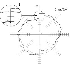
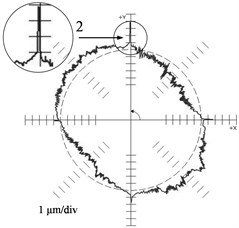
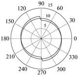
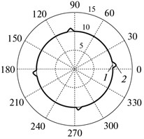
Fig. 1 represents the deviations of the reproduction of a circle 100 mm in radius as an example: (a) for the machine ФП 27 (contour feed = 500 mm/min) and (b) for machine MC 300 ( = 2000 mm/min) (JSC NIAT) found using a QC 10 ballbar device (Renishaw). Here we observe substantial differences in the behavior of the deviation curve from the reference circle during the reverse over each linear coordinate (the motion velocity of one of its units “passes” through zero). The polar diagram (Fig. 2(a)) found for the ФП 27 machine is characteristic (1 – “step”) of drives in which mechanisms with gaps are not covered by position feedback loop. The polar diagram found for the MC 300 machine is characteristic (2 – “burst”) of drives in which mechanisms with gaps are covered by position feedback loop.
Fig. 1Results of the reference circle test: a) ФП 27 machine tool (F = 500 mm/min), b) MC 300 machine tool (F = 2000 mm/min)
a)
b)
Numerous experimental and theoretical studies have been devoted to the question of the elimination of the harmful effect of gaps, friction forces, and hysteresis in deformed elements of the carrying system of the NC machine by methods of the synthesis of control systems and algorithms [1-3]. However, further investigations directed to the search for the new most efficient methods to eliminate the harmful influence of gaps, friction forces, and hysteresis on the reproduction accuracy of the spatial trajectory. Modeling in the Matlab (Simulink) and experimental investigations of ware samples are an efficient research method in this case [3, 4].
2. Model of drive
The layout of the feed drive with the use of the ball screw gear covered by position feedback loop is presented in Fig. 2 as an example of the mechanical part. The authors of [4] have described the design procedure of the simulation model of the drive over the linear coordinate of the СNC machine.
Fig. 2Layout of the feed drive along the linear coordinate with the ball screw gear: (1) motor; (2) clutch; (3, 7) bearing; (4) sensor of the rotary angle; (5) screw; (6) nut; (8) linear sensor FB; (9) table; and (10) xset is the required table position
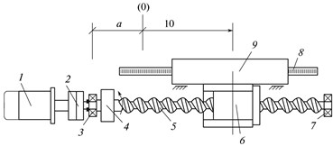
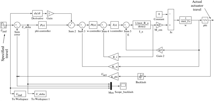
Fig. 3 shows the simulation drive model [4] in the presence of the kinematic gap in the mechanical part covered by the position feedback loop.
Fig. 3Simulation model of the servodrive with backlash in mechanical subsystem covered by position feedback loop
3. Influence of a gap on trajectory reproduction accuracy
3.1. Backlash in the mechanical system not covered by position feedback loop
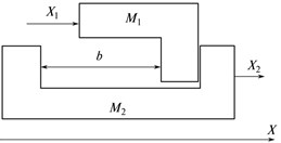
A “free travel” (backlash) is understood in mechanics (Fig. 4(a)) as a gap, i.e., the minimal magnitude of the travel of the specifying element of the mechanical system, mass М1, at which no motion of the output element of the system mass М2 is observed.
Fig. 4Backlash in the mechanical system not covered by position feedback loop: a) the interaction model of two bodies М1 and M2, b) reproduction deviations of the reference circle in the polar system of coordinates, and c) travel of body M2 in the quasi-static mode
a)
b)
c)
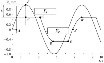
Fig. 4(c) shows how travel X (input signal , displacement of mass M1 on the X axis during movement over the reference circle), is transformed into travel M2 (output signal ) in the backlash presence. The backlash magnitude equals the BE segment, 2π/10 rad/s.
The shape of segment AB of the output signal coincides with the input signal and is shifted downwards by backlash magnitude. Segment BC corresponds to the motion of mass М1 in the backlash. After the backlash is taken up, the shape of segment CD of the output signal coincides by the input one and is shifted upwards by the backlash magnitude. Segment DE corresponds to the travel of mass М1 in backlash. After backlash is taken up, the shape of segment EA’B’ of the output signal coincides with the input signal and is shifted downwards by the backlash magnitude, etc. If we consider the execution of two sinusoidal signals X1 without backlash and Y1 with backlash according to the diagram of Figs. 4(a) and 4(b), we will acquire the pattern presented in Fig. 4(c) (found using modeling). Here, input signals X1 and Y1 are depicted by a dotted line (reference circle), while output signals X2 and Y2 are depicted by the solid line (actual trajectory). The considered case corresponds to the execution of the “circle” trajectory by the drive over X without backlash and drive over Y with backlash not covered by the position feedback.
3.2. Backlash in the mechanical system covered by position feedback loop
The pattern of the influence of backlash on the execution of the input signal in the mechanical system covered by the position feedback loop changes in principle.
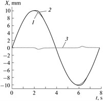
The deviation of the actual position of the actuator from the specified one as applied to modeling the carrying system of the drive over the linear coordinate (Fig. 3) is shown in Fig. 5. The following curves are displayed in the oscillograph (“Scope backlash” unit, Fig. 3): (1) setpoint for the rotary angle (2) readings of the rotary angle sensor for the travel of the backlash system, and (3) the mismatch signal (the difference between the specified and actual rotary angle of the output shaft-actuator, entering the controller input. It is seen that the variation in the direction of the drive travel is accompanied by a characteristic “projection” (curve 2) when the signal from the rotary angle sensor shows a constant value for a certain time. If we consider actuator motion over the reference circle implemented by two linear drives arranged orthogonally relative to one another, then the deviations of the actual trajectory from the specified one take the form shown in Fig. 5(b), where the radius of the reference circle is 10 mm, the gap is 0.4 mm, the traversal is counterclockwise, 1 is the reference circle, and 2 is the actual trajectory. To construct these deviations in the polar system of coordinates, Simulink blocks U_zad and U_delta (Fig. 3) are used.
Fig. 5Reproduction accuracy of the reference travel: a) deviations when reproducing the reference sinusoidal travel in the presence of the FB-enveloped backlash, where (1) is the input signal (specified value), (2) is the output signal (actual value), and (3) is the error signal (the difference between the actual and specified values); b) reproduction deviations of the reference circle in the polar coordinate system
a)
b)
The backlash in the mechanical part of the drive in principle differently affects the reversal accuracy of the “circle” trajectory depending on whether the mechanical part of the drive is covered by the position feedback loop.
Backlash magnitude in the mechanical part covered by position feedback loop directly determines the “burst” size during the reversal of the reference circle with the help of two orthogonal linear drives under the assumption of the absence of other nonlinearities as “friction”, “elasticity hysteresis”, etc.
4. Influence of the friction on trajectory reproduction accuracy
4.1. Model of the friction
Dry friction in the model implemented by “Dry friction” unit, generating disturbance torque depending by the actual speed value (Fig. 6(a)). Fig. 6(b) shows an implementation of the “dry friction” unit in the Simulink environment.
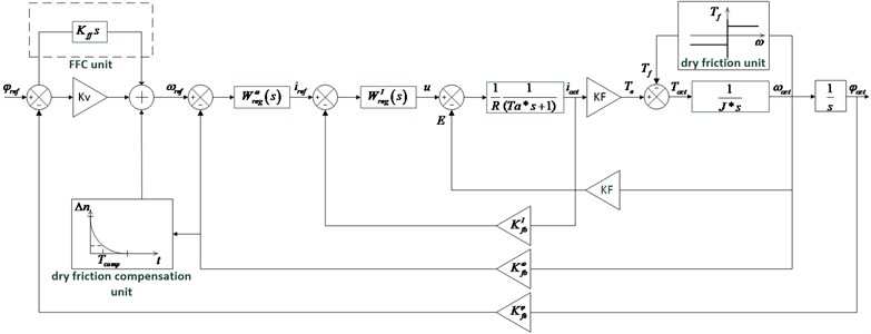
Fig. 7 shows a simulation model of the electrical drive with friction in mechanical subsystem, covered by position feedback loop. In order to improve the moving accuracy, feedforward control was implemented.
Total compensation signal consists of the output signal of FFC unit and output signal of dry friction compensation unit.
Dry friction compensation unit performs correction signal when the drive changes its moving direction. Shape of the correction signal determined by signal amplitude value and by time constant , which determines the rate of decay of the output signal [3].
Fig. 6Implementation of dry friction in the model: a) Mω curve; b) unit “Dry friction” implemented in Simulink environment
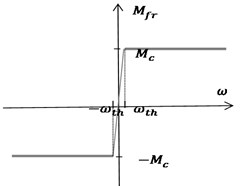
a)
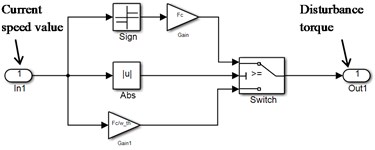
b)
Fig. 7Simulation model of the electrical drive with friction in mechanical subsystem covered by position feedback loop
4.2. Modeling system with friction
Fig. 8Simulation results of modeling system with friction: a) reproducing the reference sinusoidal signal by one drive; b) reproducing the reference circle in the polar coordinate system
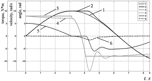
a)
b)
Fig. 8(a) shows results of modeling of reproducing the reference sinusoidal signal by one servo drive with friction. The following curves are depicted on the chart: (1) setpoint for the rotary angle, (2) readings of the rotary angle sensor for the travel of the system with dry friction, (3) disturbance torque, (4) drive torque on the motor shaft, (5) speed of the motor shaft, (6) error signal.
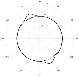
Fig. 8(b) shows results of modeling actuator motion over the reference circle implemented by two linear drives arranged orthogonally relative to one another. It is seen, that the form of the burst is close to that produced by system with backlash covered by position feedback loop.
It is seen, how friction changes motion: when drive changes its moving direction, we can see characteristic “stagnation”, i.e. time period when the motor shaft is not moving. This effect is due to a disturbance torque jump when drive speed sign changes. The system will remain fixed until the torque on the motor shaft exceeds the value of friction torque.
If friction compensation unit is “on”, speed setpoint signal is summed with additional correction signal when drive changes its moving direction. In this case difference between reference and actual speed values is increasing, as a result current controller reference signal is also increasing, therefore drive produces required torque much quicker.
The values of and corresponding to the minimum of the burst value for a real machine tool can be obtained by measuring burst values during experiments with ballbar equipment by trial-and-error method. Burst can be compensated by about 80 % with optimally adjusted values [5]. It should be noted that these values are optimal only for feed speed, at which burst measuring and values selection was made.
5. Conclusions
1) Digital correction of servo drive input signal is an effective technique for reducing dynamic errors such as “bursts” during movement along smooth paths on sculptured surfaces (e.g. turbine blades)
2) Reproduction deviations of the reference circle are visually similar in the system with backlash and system with friction-type nonlinearities.
References
-
Marchi J. A. Modeling of Dynamic Friction, Impact Backlash and Elastic Compliance Nonlinearities in Machine Tools, with Applications to Asymmetric Viscous and Kinetic Friction Identification. Rensselaer Polytechnic Institute, Troy, http://www.perihelia.com/doc/phdweb.pdf, 1998.
-
Armstrong-Helouvry B., Dupont P., De Wit C. C. A survey of models, analysis tools and compensation methods for the control of machines with friction. Automatica, Vol. 30, Issue 7, 1994, p. 1083-1138.
-
Andreichikov B. Dinamicheskaya Tochnost’ Sistem Programmnogo Upravleniya Stankami (Dynamical Accuracy for Lathes Program Control Systems). Mashinostroenie, Moscow, 1964, (in Russian).
-
Pas’ O., Serkov N. The way to simulate bearing system response to step power excitation for multi-coordinate machine with numerical program control. Proceedings of the 3rd International Science Conference “Fundamental Researches and Innovation Technologies in Machinery Manufacturing”, 2014, p. 225-227, (in Russian).
-
Pas’ O., Serkov N. Correction of servo drive dynamic errors caused by dry friction. Proceedings of the 3rd International School for Young Scientists “Nonlinear Dynamics of Machines”, 2016, p. 245-251, (in Russian).
About this article

