Abstract
The paper considers the problem of the analysis of the dynamic characteristics of assembly rotors of modern gas turbine engines (GTE). Dynamic equation solution is built based on the finite element method (FEM) and using the modified method of numerical integration of Newmark. Additionally, at each step of integration over time is spent solution of the contact problem of elasticity required for modeling the interaction of joint parts in the rotor. Nonlinear contact problem solution is built using the method of “penalty” in addressing the inequalities of the second kind Fredholm. Accordingly, analyzes and changing the dynamic characteristics of the rotor. Mathematical modeling of the rotor excitation is carried out by force and torque imbalances that are set in the finite element (FE) model drives assembly rotor components of its structure. The results of the calculation of the high-pressure turbine engine rotor in the form of plots of dynamic movements on elastic supports the rotor. The brief analysis of the calculation results and the comparison of critical speeds FE model assembly rotor and FE models of its monolithic analog (prototype). Also, in the work we present an analysis of the dynamic characteristics of the two-Shaft (two-stage) rotary GTE system to the presence of her cross-bearing rampart. Computer implementation used in the mathematical modeling carried out on the basis of high-level algorithmic language FORTRAN. Construction of FE models of rotor systems implemented in the software package MSC Patran.
1. Introduction
Modern development of turbomachinery rotor systems heavily, such as aviation gas turbine engines (GTE), based on the principles of multi-cascade (multi-valnosti) and improving the operating parameters [1-4]. In this case, the basic approach in determining the dynamic characteristics of the rotor, and, in particular, critical rotation speed, are data races its counterparts. One of the main reasons for this is that the rotors GTE is principally assembly constructs, lots of different parts to be joined and a variety of design solutions for their conjugation. The stiffness of assembly rotors differs from the stiffness of its monolithic counterpart to a large extent and, most importantly, has the ability to change during the promotion of the rotor.
Thus, besides the known effect of physical factors on the critical rotor speed [1-7] GTE remains unknown influence on its interpretation of the dynamic parameters of the conjugation conditions therein working parts. The most relevant in this case, is the study of dangerous proximity to the critical frequency range of operating rotor speeds, as well as increasing the overall level of the vibration amplitude.
2. Main text
The equation of motion of elastic systems under the influence of periodic and non-periodic external forces, using the finite element method (FEM) is [8-10]:
where – mass matrix; – Matrix of damping coefficients; – matrix assembly design of the rotor stiffness; , and – accordingly, the acceleration vector, velocity and displacement nodes of finite-element (FE) models, which are the main unknowns; – vector of external forces. Building mass and damping matrices known procedure presented in [8-10]. That is, the main features of the analysis of the dynamics of assembly rotary GTE system associated with the construction of its stiffness matrix.
In [11], based on the results of field tests of assembly rotary systems, a spindle lathes, it is shown that the level of strain in the joints of parts, in particular their amount can reach up to 80 % of the total level of deformations of the rotor. Accordingly, the remaining percentage is accounted for by the deformation of structural parts themselves constituting the rotor. Based on the submitted circumstance in [11], to determine the stiffness properties assembly rotor, using two concepts: the stiffness of the contact, depending on the conditions of coupling joints of parts, and the rigidity of parts, depending on their geometric shapes and sizes, as well as the elastic properties of the material. Thus, the expression of matrix based on the finite element method for the determination of the global stiffness matrix of the rotor has the form assembly:
where – [8-9, 12-14] stiffness matrix structural parts of the rotor and the contact stiffness matrix – used for mathematical modeling of the mating parts. In addition, the expression (2) is composed of the stiffness matrix of the gyroscopic effect of the rotor – and the stiffness matrix of the initial stresses in its details – .
Matrix rigidity of the rotor parts – is made up of the symmetric positive definite matrix and stiffness of individual rotor components [12-14], each of which, in turn, is formed by summation of the matrix finite element (FE), incoming FE model in detail. Thus, we have the expressions of the form:
where – the number of FE constituting the th item; – Matrix of the gradient of the forms of FE in the three-dimensional polar cylindrical coordinate system, – the matrix of elastic constants of the material FE [8, 9, 12-15]; – volume of FE.
Global vector nodal forces in the expression Eq. (1) is represented by expression Eq. (4), and includes vectors: centrifugal forces – , gravity – [8-9], forces the contact interaction rotor parts – and the forces of static and dynamic rotor imbalances – :
Mathematical modeling of the interaction of the contact parts of the rotor due to the formation and modification of the two components of Eq. (2) and Eq. (4). This matrix contact stiffness – , which together form the vector of contact forces – . Mates rotor parts modeled a special type of finite element (Fig. 1), Which is called in [12] the contact element adjacent construction – CEAC. This FE is built using the principle of “node-to-node” and is installed on all grids surfaces abutting each other.
In the initial state, the construction of the rotor FE model for the CEAC is given the value of its initial disclosure – . In the simulation, interference, we have: and the initial state of CEAC – “closed”. In the simulation, the gap we have: , and CEAC state – “open”. In the case of simulation interface on the nominal size: – CEAC – “closed”.
Fig. 1Interaction model of contact parts: a gap (left) and with interference (from the right)
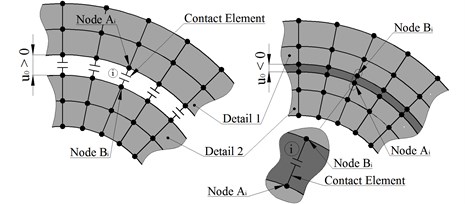
In the course of solving the system of equations of the FEM CEAC status of each can vary, from state “open” to a “closed” and vice versa. In this connection, the solution is performed iteratively and stops at the th iteration, if the status of all CEAC has not changed in comparison with the iteration 1. The rating CEAC state based on an analysis of the residual (inequality) of the field of displacements of its nodes to be determined expression of the form:
where and – displacement nodes and th (Fig. 1). At the same time, “closed” if the – “open”, if the – . Change CEAC states during solution causes a modification of the global stiffness matrix – directly in the solution by adding to it the contact stiffness matrix:
where the stiffness matrix: – open :
and closed :
where and – open CEAC stiffness in axial and tangential direction – the value, according to studies [12, 13], two or three orders of magnitude less than the minimum stiffness in FE nodes detail is necessary and sufficient for the conditioning of the global stiffness matrix; – stiffness “penalty” CEAC closed in the axial direction, is selected for two or three orders of magnitude greater than the maximum stiffness at the nodes of finite element model of a part; the determination of the hardness of the tangential direction – , in this case, is given in [12, 13], such as Coulomb friction model.
The vector of contact forces is calculated according to the expressions:
The contact forces applied to the nodes of CEAC have opposite signs and, when closed CEAC, eliminate conditional entry interfaces of parts (Fig. 1), thus, provide for the common strain abutting surfaces FE model of mating bodies.
The main forces of the rotor exciting oscillations [3-7] are components of the vector – included in the expression Eq. (4) in the form of forces and moments from the imbalances of the rotor (Fig. 2): static – where – rotor mass; – radial eccentricity; dynamic and – where – the moment of inertia of the rotor relative to the axis of symmetry; – angular eccentricity.
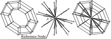
Extrapolating a special finite element is used to specify the imbalances in the model (Fig. 3). This element joins the FE model nodes with a reference rotor disc assembly arranged strictly on the rotational axis. For the reference node is defined by static and dynamic imbalance, which is converted to the forces applied to the nodes of the disk according to the expression of the form:
where – mass concentrated at the th node of the disk related FE; and – eccentricities th disk node:
and – the angular coordinates of the position and eccentricities; and – the polar coordinates of -th disc node.
Fig. 2Rotor imbalance
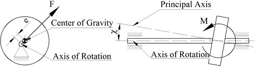
Fig. 3Modeling imbalances extrapolated FE
The solution of Eq. (1) is reduced to its numerical integration using Newmark method [6, 7, 9, 12], that reduces Eq. (1) to the form:
where – the number of time slots – .
The classical approach to the Newmark method [9] involves mixing the three unknown variables to one:
where – the dynamic stiffness matrix and – a dynamic force vector defined type expressions:
The proposed technique is effective, however, in some cases [14], and more comfortable as the basic equation the unknown applied acceleration vector.
Fig. 4The finite element model of the rotor turbine engine, the third bending vibration mode
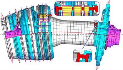
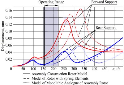
Fig. 5The results of the analysis of dynamic characteristics of assembly rotor in the form of changes in the magnitude of the displacement vector on the front and rear bearings of the rotor
The object of investigation of dynamic characteristics of all kinds of rotary systems using a high-pressure stage rotor aircraft turbine engine.
On Fig. 4 is a finite element (FE) model of the rotor turbine engine [8], designed for the analysis of its dynamic performance, where, in particular, shows a third form of flexural vibrations.
Results of comparative analysis (Fig. 5), the dynamic characteristics assembly rotor and its monolithic analog, as changes in the magnitude of the displacement vector at the front and rear bearings of the rotor show that the peak of maximum amplitude of its oscillations, determining a critical rotation frequency of the flexural vibration modes in assembly rotor shifted to the left and closer to the working range of rotor speeds. Furthermore, in the operating range increased the overall level of vibration amplitudes.
Fig. 6Finite element model (shown in section) two-stage (two rampart) of the rotor system of aviation turbine engine
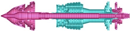
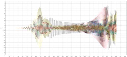
On Fig. 6 is a FE model aircraft turbine engine in diametrical section. Results of the analysis (Fig. 7), in the form of a combination of the time dependences of the displacement vector on support from the speed, show that between the peaks of increasing amplitudes that determine the value of the critical speeds, quite clearly designated area with a reduced level of vibrations, which determines the operating range of the rotation of the rotor system.
Also, the results (Fig. 7) show the presence of zones with interference amplitudes. This interference is determined using a rotary turbine system inter-bearing rampart. The least its effect is observed on the first support located farthest from him.
Fig. 7The dependence of the displacement vector at the frequency of rotation of the supports, overlapping each other
3. Conclusions
Application of FEM and the contact problem of elasticity theory in the analysis of the dynamic characteristics of the rotor turbine engine systems allows, along with increased computational costs, bring a large extent their theoretical model to the data field races. Of particular note is that the presented approach allows us to study the work of various design solutions in the rotor system, as well as to realize the prospect of studying her freelance work.
References
-
Kolotnikov M. E. Limit State of Parts and Life Prediction of Gas Turbine Engines in a Multi-Component Loading. RGATA Publications, Rybinsk, 2003, (in Russian).
-
Skubachevskij G. S. GTE, Construction and Calculation of Details. Moscow, 1981, (in Russian).
-
Hronin D. V. Theory and Calculation of Vibrations in Engines of Aircraft. Moscow, 1970, (in Russian).
-
Hronin D. V. The Construction and Design of Aircraft Gas Turbine Engines. Moscow, 1989, (in Russian).
-
Leont’ev M. K. Modern methods of calculation of dynamic characteristics of rotor systems. Nastran or Dynamics? Engine, Vol. 33, Issue 3, 2004, (in Russian).
-
Timoshenko S. P., Young S. H., Wiver U. Vibrations in Engineering. Moscow, 1985, (in Russian).
-
Babakov I. M. Theory of Vibrations. Moscow, 2004, (in Russian).
-
Zenkevich O. The Finite Element Method in the Technique. Moscow, 1975, (in Russian).
-
Bathe K., Wilson E. Numerical Methods of Analysis and Finite Element Method. Moscow, 1982, (in Russian).
-
Mjachenkov V. I., Mal’cev V. P., Majboroda V. P. Calculations of Engineering Structures Using Finite Element Method. A Handbook, Moscow, 1989, (in Russian).
-
Ryzhov E. V. Contact Stiffness of Machine Parts. Mechanical Engineering, 1966, (in Russian).
-
Pyhalov A. A. The Contact Problem of Static and Dynamic Analysis of Assembly Rotors of Turbomachines. Dr. Thesis, MAI Publications, Moscow, 2006. (in Russian).
-
Pyhalov A. A., Milov A. E. The Contact Problem of Static and Dynamic Analysis of Assembly Rotors of Turbomachines. Monograph. ISTU Publications, Irkutsk, 2007, (in Russian).
-
Dudaev M. A., Pyhalov A. A. Contact problem in the analysis of the dynamic behavior of assembly rotors of turbomachines. Scientific Bulletin of the Novosibirsk State Technical University, Vol. 3, 2015, p. 113-129, (in Russian).
About this article

