Abstract
Structural characteristics of a certain type of gas turbine double rotor and its hull are analyzed. The wave of a regular form is considered, and the wave load is simplified to the form of sinusoidal force. The rubbing force and nonlinear supporting force of the bearing are deduced as per the Hertz contact theory and Coulomb friction law. The mechanical model of the double rotor system under the combined action of the wave load and rotor friction impact is established, which is solved by the fourth-order Runge-Kutta method. The bifurcation diagram, phase diagram, Poincare section diagram, axis trajectory diagrams, effects of rotor eccentricity, and friction coefficient on the nonlinear dynamic characteristics of the system under rub impact fault are studied. The obtained results show that with an increase in eccentricity, the system enters into a chaotic state through the period doubling and paroxysmal bifurcations, and successively experiences nonlinear behaviors such as periodic 2 bifurcation, periodic 4 bifurcation, and quasi periodic and chaos. In the double rotor system, the nonlinear dynamic behavior of the single period and semi Nermark-Sacker bifurcation occurs with increasing friction coefficient. The present findings can provide a theoretical basis for condition monitoring, fault diagnosis, and design optimization of this type of gas turbine double rotor system.
1. Introduction
With the development of the economy, gas turbine, whose operational structure is mainly a double rotor system, is more and more widely used in the marine field. Considering the performance and economy of gas turbine, the radial clearance between the rotor blade and casing is designed to be smaller and smaller. Research shows that reducing the tip clearance among the compressor blade, turbine blade and casing can effectively reduce the air intake loss and fuel consumption, and improve the work efficiency of the compressor and turbine. The structure of a certain type of ship has the characteristics of small tonnage, high speed, small structural stiffness, and flat ship shape. When sailing at a high speed, the pitch and heave cause periodic slamming between the waves and bow, resulting in hull flutter. At the same time, the gas turbine rotor rotates at a high speed for a long time in the environment of high temperature and high pressure, which may easily cause the imbalance fault of the rotor, aggravate the vibration of the gas turbine rotor, and cause the rub impact fault between the rotor and the gearbox. Therefore, this paper takes the gas turbine double rotor system as the research object. The nonlinear dynamic behavior of the double rotor system under wave load is studied, which provides a reference for the design of gas turbine.
Scholars have conducted a lot of research on the rotor rub impact. In reference [1], some models of the rub impact force were established based on the Coulomb friction law and generalized Coulomb law by considering cubic dependence of the relative slip speed and the effects of two different models on the bifurcation and chaos characteristics of the rotor. The phenomena of period doubling bifurcation, Hopf bifurcation and saddle point bifurcation of the Jeffcott rotor during rub impact were studied in reference [2]. Literature [3] studied the bifurcation and chaos characteristics of the Jeffcott rotor when the rub impact fault occurs, and three ways to cause chaos were found. In reference [4], the nonlinear behavior of grazing bifurcation into chaos was studied when the friction between the disk and shell was caused by increasing rotor speed. In reference [5], considering the rotor static rub impact caused by sudden impact excitation and sudden unbalanced excitation, the nonlinear response of the rotor system under different rub impact forms were studied by using finite element method. Literature [6] studied the friction impact between the rotor and stator caused by blade falling off, and analyzed the important role of the friction coefficient and diaphragm model. Reference [7] proposed a new Poincare section method that can identify the nonlinear behavior in the process of rub impact more accurately. The influence of bearing waviness on the nonlinear dynamics of a low pressure gas turbine rotor system was studied in reference [8]. Reference [9] studied the effects of speed and bearing clearance on the nonlinear response of three supported double span rotor bearing system. According to the linear contact force and Coulomb friction force, a model of friction force was established in reference [10], and a new continuous shooting method was proposed to get the way for the system to enter and leave chaos. In reference [11], a sudden unbalance was added to the double rotor system, resulting in rub impact-, where a new way of entering into chaos through torus intersection was found. In reference [12], a finite element dynamic model of steam turbine rotor was established by considering the effect of air flow excitation force to study the changes of the nonlinear response of bearing when local rub impact occurs at different positions. In reference [13], the effects of oil film force and rub impact force on the bifurcation and chaos characteristics of single span double disk rub impact rotor system were studied by a numerical method, and experiments were designed to verify the correctness of the model. Reference [14] established a dynamic model of the double rotor system by considering the rub impact fault, studied the nonlinear dynamic response characteristics of the system under three different conditions: slight rub impact, heavy rub impact, and serious rub impact. Some achievements have been made by M. Sayed, et al in reference [15, 16].
In the dynamic modeling of the rotor system in the above research, the influence of the actual working environment of the rotor was ignored, and the bearing was considered as a linear support with stiffness and damping so the model was not practical enough. Therefore, in this paper, the wave load is simplified as a simple harmonic force acting on the double rotor system, and the nonlinear bearing force of the bearing and the rub impact force of the rotor are deduced according to the elastic Hertz theory. The dynamic model of the double rotor system with wave load rotor rub impact coupling is also established, and the bifurcation and chaos characteristics of the system when the rotor eccentricity changes are studied. The present findings provide a theoretical basis for condition monitoring and fault diagnosis of the actual gas turbine rotor rub impact fault.
2. Dynamic model of double rotor system
2.1. Model diagram
In this paper, the dual rotor system of a marine gas turbine is taken as the research object. The dual rotor system model is obtained by the centralized mass method as shown in Fig. 1, where , , and are the centroids of bearings 1, 2, 3 and 4, respectively. , and are the centroids of discs 1, 2 and 3, respectively. , and are the centroids of discs 1, 2 and 3, respectively. , and are the eccentricities of discs 1, 2 and 3, respectively. Assuming that the structural materials of shafts 1 and 2 are the same, the stiffness relationship between each shaft section is obtained according to the plane beam structure relationship, where , , and . The inner and outer rotors are connected through intermediate bearing 2. Bearings 1, 3 and 4 connect the rotor with the gearbox. See Table 1 for structural parameters of double rotors and Table 2 for bearing parameters.
Fig. 1Schematic diagram of rubbing fault of double rotors
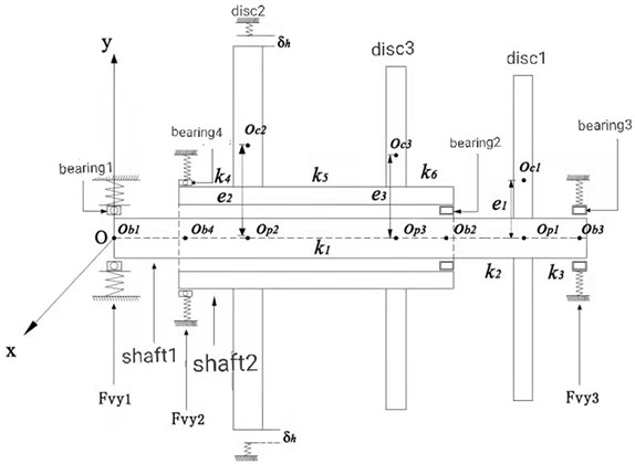
Table 1Structural parameters of double rotors
Parameter name | Parameter symbol | Dimension |
Bearing quality | , , , | Kg |
Quality of disc | , , | Kg |
Bearing damping | , , , | N∙s/m |
Table 2Parameters of bearings
Parameter | Dimension | bearing 1 | bearing 2 | bearing 3 | bearing 4 |
Internal diameter | mm | 22 | 25 | 40 | 30 |
External diameter | mm | 50 | 47 | 64 | 62 |
Number of rolling elements | number | 7 | 15 | 8 | 12 |
Radial clearance | m | 12×10-6 | 12×10-6 | 12×10-6 | 12×10-6 |
Contact stiffness | N/m3/2 | 13.34×10⁹ | 3×10⁸ | 7.055×10⁹ | 7.055×10⁹ |
2.2. Model of external load, bearing force and rubbing force
Waves can be divided into regular waves and irregular waves. The waveform contours of regular waves can be expressed by a cosine function as shown in Fig. 2.
Fig. 2Schematic diagram of regular waves
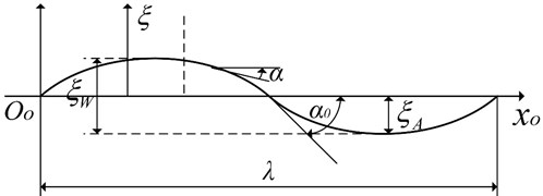
The wave surface of cosine wave propagating along direction can be expressed by Eq. (1):
where, is the rise of wave surface; is the wave amplitude that refers to the distance between the wave crest and trough from the horizontal plane with the wave height ; is the wave number equal to 2 times the number of waves appearing on the unit distance; is the wave frequency; is the wave inclination that indicates the inclination of the wave surface; is the maximum wave inclination which is conventionally called the wave inclination; and represents the wavelength equal to the distance between two adjacent peaks and troughs. Yao [15] studied the calculation method for the load of the fully padded hovercraft under regular waves, and deduced the dynamic pressure of the hovercraft as in Eq. (2):
where and are the matrices related to the geometric characteristics of the ship and wave parameters, respectively, and is the wave frequency. In this paper, the wave surface is considered as the ideal state of a regular wave, and the wave load is simplified as a sinusoidal force. If the period is 1 s and the maximum amplitude of load is 100 N, and the action of the wave load only along the direction is considered, then . It acts on the three support bearing positions connected with the gearbox of the double rotor system as shown in Fig. 1.
In this paper, the influence of the bearing oil film force on the system is ignored. According to the Hertz contact theory, the elastic contact force between the bearing rolling element and raceway is considered to reflect the influence of the bearing nonlinear force on the system. Fig. 3 shows the rolling bearing model, where is the inner diameter of the bearing, is the outer diameter of the bearing, represents the radial clearance of the bearing, is the inner ring speed, is the outer ring speed, represents the th rolling element, is the position angle of the th rolling body, and the coordinates after the motion of the axis diameter centroid are and .
Fig. 3Model diagram of rolling bearing
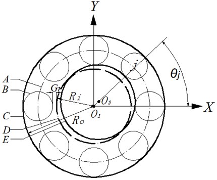
The common angular speed of the rolling element:, angular position of the th rolling element: , , and contact deformation of the th rolling element: . A contact can produce a positive contact force only. When the contact deformation is , there will be no pressure. Therefore, the Heaviside function is introduced as follows:
The nonlinear bearing force of a rolling bearing is deduced according to the Hertz contact theory, and it is expressed by Eq. (3), where BK is the nonlinear Hertz contact stiffness, 3/2 for ball bearings 1 and 4, and 10/9 for roller bearings 2 and 3:
Fig. 4The friction model
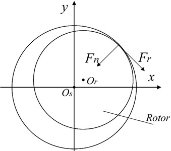
The rub impact model is shown in Fig. 4. The deformation relationship caused by rub impact is treated according to the contact deformation of the disc and circular hole with certain width and thickness, which simplifies the problem to the contact relationship of two inscribed circles. The collision force acts along the common normal line of the inscribed circles, and the friction force is perpendicular to it. According to the Hertz contact theory, there is a 3/2 nonlinear relationship between the elastic force generated by collision deformation and the amount of deformation. Local elastic deformation takes place during the collision and extrusion of two inscribed circles. The collision force is obtained as . The friction between the rotating stators meets the Coulomb’s law of friction. The friction coefficient is a fixed parameter and it is independent of relative speed. The relation of friction is obtained. According to the assumptions, the friction force can be expressed as in Eq. (4):
where , , , , and are the Poisson’s ratio, elastic modulus, and radius of the stator and rotor, respectively. is the friction coefficient between the rotor and stator. and are the friction forces along the direction and direction, respectively. is the initial clearance between the rotor and stator, is the radial displacement of the rotor, and is the elastic deformation of the rotating static contact. The parameters are as follows: the compressor blade material is titanium alloy TC4, whose elastic modulus 1.05×10¹¹N/m2 and Poisson’s ratio 0.34. The casing material is cast steel, whose elastic modulus is 2×10¹¹ N/m2, Poisson’s ratio 0.3, and 0.1 m.
2.3. Differential equation of motion of system
The dynamic model of marine gas turbine double rotor system established in this paper has 7 lumped masses and 14 degrees of freedom. Assuming that the rotating shaft is an elastic shaft without mass, only the transverse vibration of the rotor is considered by ignoring both torsional vibration and axial vibration. Accordingly, the differential equation of motion of the system is derived from the Lagrange equation of motion as expressed by Eq. (5):
where:
In Eq. (5), is the system mass matrix, is the system damping matrix, is the system stiffness matrix, and are the bearing force matrices, and are the rotor unbalance force matrices, is the wave load simple harmonic force matrix, and and are the rub impact force matrices. Further, is the speed of rotor 1, is the speed and is the peed ratio of the rotor. Dimensionless parameter is the reference value of the dimensionless length. Other introduced dimensionless parameters are as follows:
For ball bearings, 1/2; and for cylindrical roller bearings, 1/9. According to the dimensionless parameters and Eq. (5), the dimensionless equations are obtained as expressed by Eq. (6):
According to the high-speed operational characteristics of the rotor of a gas turbine generator, reasonable simplification is carried out to facilitate the modeling of the rub impact fault of the rotor system. The following assumptions are made: (1) nonlinear elastic collision occurs at the contact position when the rotating stator collides with friction; (2) the friction satisfies the Coulomb's law of friction; (3) the thermal effect caused by friction is ignored; and (4) the damping effect in the process of collision deformation is ignored. Based on the above assumptions, the rub impact force model of gas turbine and gas generator rotor is established as per the Hertz contact theory and Coulomb friction law.
3. Bifurcation and chaos characteristics of two rotor system under rub impact fault
The double rotor structure characteristics of a marine gas turbine are analyzed. The rotor speed of the gas generator is high, and the blade length of the compressor is greater than that of the turbine. When the rotor system vibration is too large, the compressor is more likely to collide with the casing, making the nonlinear characteristics of the system more complex. Therefore, the compressor rotor and disk 2 are also taken as the research object, and the influence of rotor unbalance and friction coefficient on the nonlinear characteristics of the system is analyzed.
3.1. Influence of eccentricity on Bifurcation and chaos characteristics of double rotor system
Rotor unbalance is one of the major reasons for abnormal vibration and excessive response amplitude of the rotor, which leads to the rub impact fault between the rotor and stator. It has a significant impact on the nonlinear response characteristics of the double rotor system. Various parameter values are set here as follows: speed of rotor 2, 1680 rad/s; initial clearance, 20 μm; and friction coefficient 0.1. Taking the eccentricity of disk 2 as the bifurcation parameter, is studied in the range of 0 to 30 μm. When is changed, the bifurcation and chaos characteristics of the system also change.
A bifurcation diagram of the variation of the horizontal displacement of disc 2 with eccentricity is shown in Fig. 5, where it can be seen that disc 2 exhibits rich nonlinear dynamic behavior with increasing eccentricity. When the eccentricity is small, disk 2 is in a chaotic state. When the eccentricity is increased to 7 μm, disk 2 enters into cycle 2 through inverted bifurcation and moves at 10 μm to enter into the chaotic state through the period doubling bifurcation road. When the eccentricity continues to increase to 13 μm, disk 2 enters into the state of periodic four motion through the inverted bifurcation path, and then enters into the chaos through the period doubling bifurcation path. When the eccentricity is increased to 20 μm, disk 2 enters into the quasi periodic motion through the inverted bifurcation path, and then enters into the chaos through the paroxysmal bifurcation path. The bifurcation and chaos characteristics of disk 2 are analyzed by selecting different values of eccentricity.
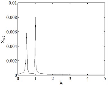
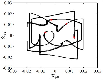
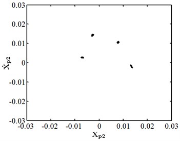
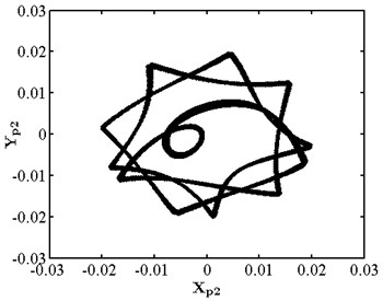
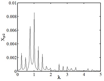
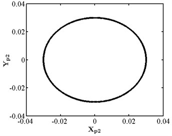
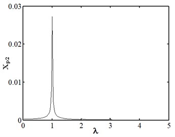
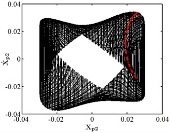
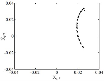
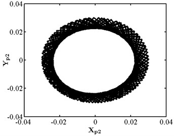
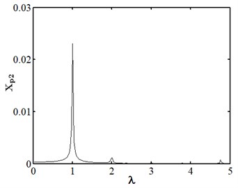
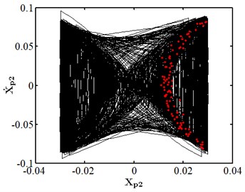
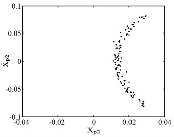
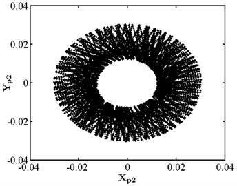
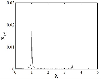
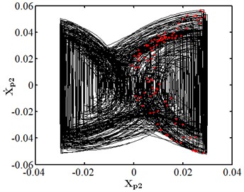
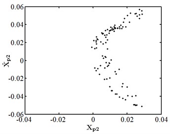
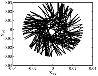
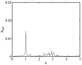
When eccentricity = 10 μm as shown in Fig. 6, the phase trajectory of disk 2 forms two closed circular orbits, which are mapped into two isolated point sets through Poincare. The axis trajectory is in the shape of "8". In the spectrum diagram, it is mainly frequency conversion and 1/2 frequency doubling. At this moment, disk 2 moves in cycle two. When eccentricity = 13 μM for disc 2 as shown in Fig. 7, its phase trajectory forms four closed orbits. Due to the action of rubbing, the amplitude of disc 2 becomes 20 μm. The “cutting” phenomenon occurs at . Poincare is mapped into four isolated points. The conversion frequency is the main excitation frequency of disk 2. There are also 0.25 octave, 0.5 octave, 0.75 octave, 1.25 octave and 1.5 octave. At this moment, disk 2 makes periodic four motion. When eccentricity = 20 μM for disc 2 as shown in Fig. 8, its phase trajectory produces a “cutting” phenomenon due to the friction impact. Poincare maps to a certain section to form an unsealed semicircular curve, and the axis trajectory presents a regular state of periodic motion. In the spectrum diagram, frequency conversion is the main, with 2-fold, 3-fold and 5-fold frequency. At this moment, disk 2 makes quasi periodic motion.
Fig. 5Bifurcation diagram of disk 2 with eccentricity
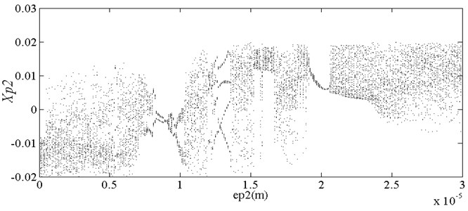
Fig. 6Nonlinear dynamic characteristic diagram of disk 2 at ep2= 10 μm
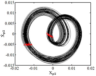
a) Phase diagram
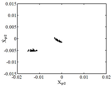
b) Poincare section
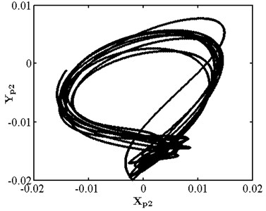
c) Axis trajectory
d) Spectrum diagram
Fig. 7Nonlinear dynamic characteristic diagram of disk 2 at ep2= 13 μm
a) Phase diagram
b) Poincare section
c) Axis trajectory
d) Spectrum diagram
Fig. 8Nonlinear dynamic characteristic diagram of disk 2 at ep2= 20 μm
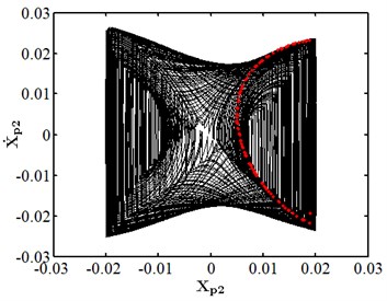
a) Phase diagram
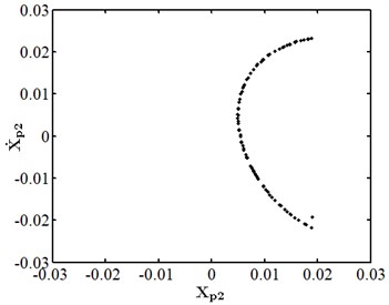
b) Poincare section
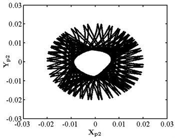
c) Axis trajectory
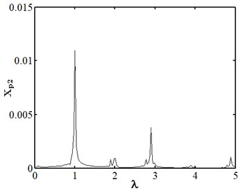
d) Spectrum diagram
3.2. Influence of friction coefficient on Bifurcation and chaos characteristics of double rotor system
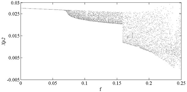
By analyzing the rub impact force model, the friction generated by rub impact is determined by the contact displacement and friction coefficient between the rotor and stator. When rub impact occurs between the rotor and stator, the material characteristics of the rotor-stator contact surface change due to the thermal effect and other factors, and the friction coefficient also changes. Various parameters are set here as follows: speed of rotor 2, 1000 rad/s; initial clearance 30 μm; and 10 μm. Taking the friction coefficient between the rotor and stator as the bifurcation parameter, the influence of the change in on the bifurcation and chaos characteristics of the system is studied.
As shown in Fig. 9, the horizontal displacement of disk 2 changes with the friction coefficient. When the amplitude of disk 2 is too large, it will rub with the stator. At this moment, the “cutting” phenomenon occurs in the bifurcation diagram. It is seen in the figure that the displacement response of disk 2 is only half, and the vibration amplitude of the other half cannot continue to increase due to the rubbing. When the friction coefficient is small, the rubbing force has little effect on the nonlinear characteristics of disc 2. With increasing friction coefficient, the bifurcation and chaos characteristics of disk 2 change, and the nonlinear behavior becomes more complex.
Fig. 9Bifurcation diagram of disk 2 with friction coefficient
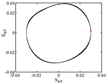
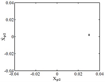
When the friction coefficient is small, the friction effect is also small, and it will not have a significant impact on the nonlinear response of the system. As shown in Fig. 10, when the friction coefficient is 0.01, the nonlinear dynamic characteristics of disc 2 are the same as those at the same speed as stated in section 3.4.1, and they are in the state of a single cycle motion. At this moment, the impact of friction is small. When the friction coefficient is 0.1 as shown in Fig. 11, disc 2 is in the state of a quasi-periodic motion. When the friction coefficient is 0.2 as shown in Fig. 12, the friction is large, the impact of the rub impact fault is enhanced, the phase trajectory in the phase diagram of disk 2 forms a more complex track pattern, the scattered points on the Poincare section tend to be irregularly distributed, the axis trajectory gets the characteristics of periodic motion, the transfer frequency in the spectrum diagram is the main frequency, and the 3.5 times frequency is the secondary frequency. At this moment, disk 2 tends to transform from quasi periodic motion to chaos. When the friction coefficient is 0.25 as shown in Fig. 13, the phase trajectories of disc 2 are staggered, the points in Poincare section are scattered, the axis trajectory is in the state of an irregular motion, the transfer frequency in the spectrum is the main frequency, and a continuous frequency peak appears near the third harmonic frequency, indicating that the degree of the rub impact fault is serious at this moment, causing disc 2 to enter into a chaotic state.
Fig. 10Nonlinear dynamic characteristic diagram of disk 2 at f= 0.01
a) Phase diagram
b) Poincare section
c) Axis trajectory
d) Spectrum diagram
Fig. 11Nonlinear dynamic characteristic diagram of disk 2 at f= 0.1
a) Phase diagram
b) Poincare section
c) Axis trajectory
d) Spectrum diagram
Fig. 12Nonlinear dynamic characteristic diagram of disk 2 at f= 0.2
a) Phase diagram
b) Poincare section
c) Axis trajectory
d) Spectrum diagram
Fig. 13Nonlinear dynamic characteristic diagram of disk 2 at f= 0.25
a) Phase diagram
b) Poincare section
c) Axis trajectory
d) Spectrum diagram
4. Conclusions
In this paper, the rub impact problem of rotor-stator is transformed into the contact problem of two inscribed circles. The rub impact force model is deduced according to the Hertz contact theory and Coulomb friction law. The mechanical model of a double rotor system is established by coupling wave load with the rub impact fault of the rotor. It is found that when the eccentricity of disk is small, disk 2 is in a chaotic state. When the eccentricity is increased to 10 μm, disk 2 enters into cycle 2 through inverted bifurcation, and moves at 10 μm enters the chaotic state through the period doubling bifurcation road. If the eccentricity continues to increase to 13 μm, disk 2 enters into the state of periodic four motion through the inverted bifurcation path, and then enters into chaos through the period doubling bifurcation path. Upon further increasing the eccentricity to 20 μm, disk 2 enters into the quasi periodic motion through the inverted bifurcation path, and then enters into chaos through the paroxysmal bifurcation path. These two paths to chaos can provide a theoretical basis for condition monitoring and fault diagnosis of a double rotor system.
References
-
N. Vlajic, A. R. Champneys, and B. Balachandran, “Nonlinear dynamics of a Jeffcott rotor with torsional deformations and rotor-stator contact,” International Journal of Non-Linear Mechanics, Vol. 92, pp. 102–110, Jun. 2017, https://doi.org/10.1016/j.ijnonlinmec.2017.02.002
-
S.-K. Choi and S. T. Noah, “Mode-locking and chaos in a Jeffcott rotor with bearing clearances,” Journal of Applied Mechanics, Vol. 61, No. 1, pp. 131–138, Mar. 1994, https://doi.org/10.1115/1.2901387
-
F. Chu and Z. Zhang, “Bifurcation and chaos in a rub-impact Jeffcott rotor system,” Journal of Sound and Vibration, Vol. 210, No. 1, pp. 1–18, Feb. 1998, https://doi.org/10.1006/jsvi.1997.1283
-
W. Qin, H. Su, and Y. Yang, “Grazing bifurcation and chaos in response of rubbing rotor,” Chaos, Solitons and Fractals, Vol. 37, No. 1, pp. 166–174, Jul. 2008, https://doi.org/10.1016/j.chaos.2006.08.018
-
H. Ma, Q. Zhao, X. Zhao, Q. Han, and B. Wen, “Dynamic characteristics analysis of a rotor-stator system under different rubbing forms,” Applied Mathematical Modelling, Vol. 39, No. 8, pp. 2392–2408, Apr. 2015, https://doi.org/10.1016/j.apm.2014.11.009
-
S. Roques, M. Legrand, P. Cartraud, C. Stoisser, and C. Pierre, “Modeling of a rotor speed transient response with radial rubbing,” Journal of Sound and Vibration, Vol. 329, No. 5, pp. 527–546, Mar. 2010, https://doi.org/10.1016/j.jsv.2009.09.016
-
J.-D. Jeng, Y. Kang, and Y.-P. Chang, “An alternative Poincaré section for high-order harmonic and chaotic responses of a rubbing rotor,” Journal of Sound and Vibration, Vol. 328, No. 1-2, pp. 191–202, Nov. 2009, https://doi.org/10.1016/j.jsv.2009.07.018
-
Y.-B. Liu et al., “Study on nonlinear Dynamics of low pressure rotor system under waviness fault,” (in Chinese), Journal of Naval Engineering University, Vol. 32, No. 1, pp. 50–56, 2020, https://doi.org/10.7495/j.issn.1009-3486.2020.01.009
-
M. Li, Y.-B. Liu, and Q. Wang, “Nonlinear dynamic Analysis of low pressure rotor-bearing system of Marine Gas Turbine,” (in Chinese), Journal of Bearing, Vol. 11, pp. 38–44, 2019, https://doi.org/10.19533/j.issn1000-3762.2019.11.010
-
H.-B. Zhang et al., “Bifurcation and Stability of Rub-impact response of Impeller rotor,” (in Chinese), Journal of Vibration Engineering, Vol. 32, No. 4, pp. 635–643, 2019, https://doi.org/10.16385/j.cnki.issn.1004-4523.2019.04.010
-
T. Sun, W.-Y. Qin, and H. Xiang, “Nonlinear response analysis of rub-impact of engine counter-rotating double-rotor system,” (in Chinese), Journal of Mechanical Strength, Vol. 32, No. 4, pp. 635–643, 2019, https://doi.org/10.16579/j.issn.1001.9669.2019.02.001
-
Zhang Ya et al., “Study on rub-impact dynamic characteristics of steam turbine rotor system considering flow-induced vibration,” (in Chinese), Journal of Beijing University of Chemical Technology (Natural Science Edition), Vol. 46, No. 1, pp. 76–83, 2019, https://doi.org/10.13543/j.bhxbzr.2019.01.012
-
Z.-Q. Lu, Y.-H. Wei, and J.-J. Jiao, “Dynamic simulation and experimental verification of rotor rub-impact fault,” Journal of Shenyang University of Technology, Vol. 37, No. 4, pp. 62–67, 2018.
-
Y.-Z. Jin, D.-Y. Wang, and B.-C. Wen, “Simulation study on rub-impact fault of aeroengine double-rotor system,” Journal of Harbin Engineering University, Vol. 38, No. 12, pp. 1872–1876, 2017.
-
M. Sayed, A. A. Mousa, and I. Mustafa, “Stability and bifurcation analysis of a buckled beam via active control,” Applied Mathematical Modelling, Vol. 82, pp. 649–665, Jun. 2020, https://doi.org/10.1016/j.apm.2020.01.074
-
M. Sayed and Y. S. Hamed, “Stability analysis and response of nonlinear rotor-seal system,” Journal of Vibroengineering, Vol. 16, No. 8, pp. 4152–4170, Dec. 2014.
Cited by
About this article

This work is supported by National Major Science and Technology Projects of China No. J2019-Ⅳ-0021-0089 and No. J2019-Ⅰ-0012-0012, and Hubei Provincial Central Guidance Local Science and Technology, No. 2020CFB536.
The datasets generated during and/or analyzed during the current study are available from the corresponding author on reasonable request.
The authors declare that they have no conflict of interest.
