Abstract
The article describes a mathematical model of dynamics of electromechanical drive with elastic transmission gear. A motor is connected to the tripod actuating links by self-sustaining transmission. The analytical conditions of drive dynamic seizure absence have been obtained.
1. Introduction
The tripod shown in Fig. 1 is designed to carry out handling operations. The tripod mechanism includes three controlled actuating links 1, 2, 3 ends of which are fixed with the help of special two-movable hinges on a swiveling base 5. Opposite ends of the links are connected with a special hinge joint 6 allowing geometric axis of these links to cross in one point that prevents bending moments from external loads from appearing in them. The handled item is attached to a rigid suspension which is fastened to a joint 6 [1] via cylindrical hinge.
Tripod design is reinforced that ensures high accuracy of program motions [2]. However, deformations in drive mechanisms can have a significant impact on parameters of dynamic accuracy and dynamic loads values.
Fig. 1Tripod on a swiveling base
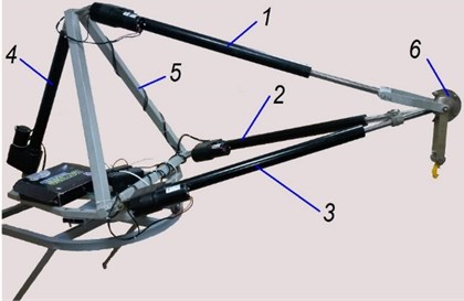
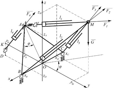
Fig. 2Design model of a tripod on a swiveling base
1.1. Tripod dynamics
To simplify the differential equations describing the tripod dynamics the real mechanism is replaced with dynamically equivalent one which contains two lumped masses: in a grip attachment point (point ) and in point of a swiveling base (Fig. 2) [3].
In this case a differential equations system describing tripod motion established through Lagrange`s equations of the second kind [4] is written as follows:
where Cartesian coordinates of point (Fig. 2) , , in absolute coordinates system (Fig. 2) and base rotation angle φ were taken as generalized coordinates of the tripod; , 1,…,4 – drive control force in tripod links.
Length of actuating links , 1,…,4 are expressed in terms of generalized coordinates of the tripod as follows [5, 6]:
Geometrical parameters , , , of the tripod base and points of its attachment on a swiveling base are shown on Fig. 2.
1.2. Drive dynamics
Each actuating link of the tripod (Fig. 3) consists of separately excited DC electric motor, irreversible worm reducer and screw gear.
Fig. 3Structural diagram of a driving mechanism of the tripod actuating link; 1 – rod; 2 – program controller; 3 – electric motor; 4 – worm reducer; 5 – screw gear; 6 – feedback transmitter; 7 – feedback controller
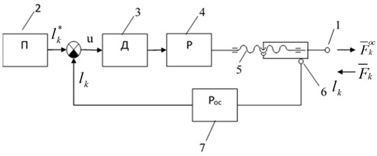
Mechanism of motion transmission from a motor to moved mass is considered to be a three-mass system consisting of an electric motor rotor with a worm, worm wheel a screw and a nut with a rod. In this case a model has three degrees of freedom. As generalized coordinates of a drive the following is selected: rotation angle of an output motor shaft (worm), rotation angle of a worm wheel and rotation angle of a screw at the inlet of a slave cylinder nut. Due to transmission yielding they differ by the value of angular deformation.
Dynamic characteristic of a separately excited DC drive motor is written as [7]:
where – motor shaft torque; – electromagnetic time constant; , – motor parameters-dependent coefficients; – control voltage; – angular velocity to a motor shaft.
Differential equations of rotational motion of a worm with electric motor rotor, a worm wheel with an electro cylinder screw of and forward motion of a nut with an actuating link rod are written as:
where , – inertia moments of a worm with a rotor and a worm wheel with a screw; , – angular acceleration of an electric motor rotor and a worm wheel; , – torques applied to a worm and to a reducer worm wheel; , – constant torques of resistance forces applied to a worm and a worm wheel shaft; – reducer efficiency factor; – gear ratio of a worm reducer; – unit stiffness of elastic linkage between motor shaft and worm wheel; – screw rigidity in torsion; – mass of a nut with an actuating link rod; – axial moving force; – rod force determined by load when tripod is in operation Eq. (2).
In case of a lead worm and efficiency factor equals to . Here – ascending angle of worm screw line; – modified friction angle. If , motion is impossible due to reducer irreversibility. In this case dynamic seizure in mechanical transmission will occur [8].
Torque on a guide rotating screw is connected to axial force acting on a nut with a rod by the expression:
where , – ascending angle of a screw line and modified friction angle respectively; – average diameter of screw thread.
Angular screw speed is connected to linear speed of actuating link motion by the relation:
From the system consisting of 32 algebraic and differential Eq. (1-8) based on the laws of control voltage variation in energizing winding of drive electric motors and initial conditions 32 unknown functions can be found: generalized coordinates of the tripod , , , , length of actuating links , force in these links and , as well as electric motor shaft torque moments and angular coordinates , , , ( 1-4).
Torque moment on an electric motor shaft can be calculated via simultaneous solution of Eq. (4-8):
Given program motion equations and introducing dynamic error , allows for going over to a disturbed motion equation.
No-dynamic seizure conditions are obtained from Eq. (4):
Therefore, expression Eq. (9) determines a permissible value of electric motor shaft torque. When there is a violation of conditions Eqs. (10, 11) dynamic seizure will occur in transmission that can entail unstable operation of a drive and even its malfunction.
1.3. Simulation results
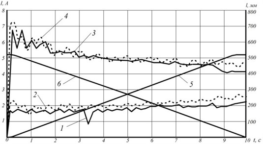
In order to determine model parameters experimental and numerical research were conducted to study dependence of tripod grip motion in plane when one (the first) slave cylinder is in operation while the control voltage was varied according to rectangular waveform , , , For out of service actuating links worm rotation angle was taken as zero and warm shaft torque was taken as . Grip load amounts to 420 N. In the process of calculations, the no-dynamic seizure conditions were monitored. A tripod control system is equipped with current sensor ACS712 designed for measuring electric drive current consumption proportional to torque developed by an electric motor [9].
In Fig. 4 presents experimental and theoretical dependences of the moment equivalent , on an electric motor shaft for two modes of tripod grip motion, namely the first cylinder extension (curve 1, 2), the first cylinder retraction (curve 3, 4), as well as experimental dependence of the first cylinder stroke length change while extending (curve 5) and retracting (curve 6).
Fig. 4Dependence of torque equivalent developed by electric motor of tripod actuating link drive: 1, 3 – experimental curves, 2, 4 – theoretical and experimental dependence of change of the first link stroke length at extending (curve 5) and retracting (curve 6)
2. Conclusions
The developed mathematical model of tripod dynamics allows for solving the issues regarding determination of electric motors torques required to perform program motions and dynamic loads in kinematic pairs of the tripod, as well as for determining dynamic errors caused by influence transmission elasticity and mechanism dynamic exert on electric motor operation.
References
-
Zhoga V., Gavrilov A., Gerasun V., Nesmianov I., Pavlovsky V., Skakunov V., Bogatyrev V., Golubev D., Dyashkin-Titov V., Vorobieva N. Walking mobile robot with manipulator-tripod. Proceedings of Romansy 20th CISM-IFToMM Symposium on Theory and Practice of Robots and Manipulators, Vol. 22, 2014, p. 463-471.
-
Glazunov V. A., Koliskor A. W., Krainev A. F. Spatial Mechanisms of Parallel Structure. Nauka, Moscow, 1991, p. 95, (in Russian).
-
Nesmiyanov I., Zhoga V., Skakunov V., Terekhov S., Vorob’eva N., Dyashkin-Titov V., Fares Ali Hussein Al-hadsha Synthesis of control algorithm and computer simulation of robotic manipulator-tripod. Communications in Computer and Information Science, Vol. 535, 2015, p. 392-404.
-
Zhoga V., Gerasun V., Nesmiyanov I., Vorob'eva N., Dyashkin-Titov V. Dynamic creation of the optimum program motion of a manipulator-tripod. Journal of Machinery Manufacture and Reliability, Vol. 44, Issue 2, 2015, p. 181-186.
-
Kolovskii M. Z., Sloushch A. V. Foundations of Industrial Robot Dynamics. Nauka, Moscow, 1998, (in Russian).
-
Korendesev A. I., Salamandra B. L., Tyves L. I. Theoretical Basis of Robotics. Institute of Machines Science named after A.A. Blagonravov of the Russian Academy of Sciences, Nauka, Moscow, Vol. 1, 2006, p. 383, (in Russian).
-
Korendesev A. I., Salamandra B. L., Tyves L. I., et al. Manipulation Systems for Robots. Mashinostroenie, Moscow, 1989, p. 427, (in Russian).
-
Vejts V. L., Vasil’kov D. V., Gidaspov I. A., Shneerson E. S. Dynamics of Drives of Process Units with Non-Reversible Devices. Monograph in 5 Parts, St. Petersburg, 2002, (in Russian).
-
Zhoga V. V., Skakunov V. N., Terehov S. E. Adaptive control system of electric driver walking robot. Journal Izvestiya VSTU, Vol. 157, Issue 2, 2015, p. 180-183, (in Russian).
About this article

The work is completed under financial support from the Russian Foundation for Basic Research (RFBR) (Contract No. 15-01-04577-а, No. 16-48-340395 р-а and No. 16-38-00485).
