Abstract
In this paper the problem of the theory of rotating machinery autobalancing to reduce their vibration is considered by example of the simplest unbalanced Jeffcott rotor with multi-bodies autobalancer. The exact analytical solution for the determination of autobalancing motion stability boundaries is given. The obvious approximate expression for the boundary rotor speed is obtained. The useful necessary condition for the stability of rotor autobalancing is obtained. It is found that there are combinations of the system parameters values under which the autobalancing cannot be stable at any rotor speeds. There is a maximum possible value of the rotor unbalance, which can be steady eliminated by autobalancer. The criterias of rotor machines with autobalancer similitude are proposed. It is shown that the external rotor damping can both stabilize or destabilize the system. The practical recommendations for the choice of autobalancer parameters values resulting from analytical expressions are given.
1. Introduction
Autobalancing devices (ABD) of the passive type are used in rotary machines to reduce their level of vibration. Their practical usage is hampered by the problem of stability which ensures the mechanical system autobalancing mode of motion (see. [1-5] and others). In turn, the solution of this problem causes the necessity of the ABD analytic theory development.
Autobalancing devices are essentially nonlinear multibody mechanical systems with non-trivial properties. This causes difficulties of their investigations. The quite complete review of researches on the autobalancing rotors theory is given in [2]. From a simple analysis of the system dynamics follows that the autobalancing of Jeffcott rotor is possible at rotor speeds above the critical speed . However, an accurate analysis shows that autobalancing mode of motion is stable not at , but at , where is the stability boundary on the rotational speed, which can be significantly higher than . The exact determination of value is difficult because of nonlinearity of the system with a large number of freedom degrees. In some studies only approximate expressions were obtained by using one of the small-parameter methods. As far as author knowns by reviewing of autobalancing theory researches, only in [6], the exact analytical solution for the determination of quantity and values of stability boundaries was obtained for the most important case of compensating bodies location in ABD.
The paper purpose is the analysis of features of the mechanical system “Jeffcott rotor – multi-bodies autobalancer” parameters influencing on the boundaries of autobalancing stability on the basis of exact analytical solution; identification of the limit possible values of certain system parameters and the formulation of the similitude criterias.
2. The physical model and the equations of motion
Let us consider the mechanical system shown in Fig. 1. The single disk isotropic unbalanced Jeffcott rotor is mounted on two elastic supports with viscous damping and rotated at a constant angular velocity . The disk mass is installed in the middle of the shaft and makes plane motion. Its center of mass is spaced from the point of the mounting disk to the shaft at a distance (eccentricity). Autobalancer located in the disk plane and designed as a cylindrical cavity with compensating bodies in the form of balls or rollers (also it is possible to use a pendulum compensating bodies). The axis of the cylindrical cavity passes through the point , in which the ABD is attached to the rotor. The number of compensating bodies is arbitrary, but not less than two, . Bodies are able to move freely on the circle of radius . The movement of one compensating body does not prevent the movement of other bodies.
The current position of the disc is described by coordinates , point , and the angular position of the th ball – angle , measured from the fixed axis .
The physical parameters of the mechanical system are following:
– angular speed of rotor rotation, radian/s;
, – mass of disc, kg, and rotor eccentricity, m;
– stiffness of the shaft and its supports, referred to the center of disc, N/m;
– the coefficient of the rotor external viscous damping, s-1;
– the critical speed of rotor rotation, radian/s;
, – the current coordinates of the disc geometric center, m;
, – mass of the compensating body (kg) and their number;
– the radius of the bodies movement circle in ABD, m;
– coefficient of internal viscous resistance to the motion of bodies in ABD, s-1;
– the current angular coordinate of the th ball relative to axis , radian;
– constant angular positions of balls relative to the disc in the autobalancing mode, 1, 2,…, , radian;
– small angular deviation of the th ball relative to , radian.
Fig. 1Mechanical system “rotor – autobalancer”
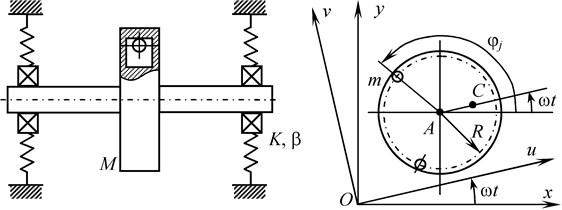
We investigate the small transverse oscillations of rotating rotor with autobalancer in the fixed system of coordinates or in the rotating coordinate .
The equations of mechanical system motion are known; see, for example, [2, 3, 6]. In the most important case of bodies position in ABD to provide stability, the equations of mechanical system perturbed motion in the fixed coordinate system have the form [6, 7]:
where:
and – the vector of generalized coordinates of mechanical system; , – the vectors of generalized coordinates of rotor and ABD; – the relative mass of the one compensating body in ABD.
The summary generalized coordinates ABD describe the displacement of the mass center of all bodies in ABD relative to its stationary position at the ideal autobalancing in the fixed coordinate system. Their descriptions see in [6, 8]. The use of these generalized coordinates of ABD minimizes the number of system motion equations to only four, instead of () equations for the complete system.
It should be noted that the system of motion Eq. (1) corresponds to such position of the compensating bodies in ABD, in which the coefficients in the equations are constant and have the simplest form. In this case, the inertia tensor of compensating bodies ABD is isotropic. This extends the capability of the analytical research without cumbersome conversion in equations to rotating axes when considering the general case. On the other hand, as shown in [3, 6, 7], it is the most problematic case for providing of autobalancing stability. Therefore, if in this case the autobalancing is stable, then it will be stable in all other cases, during operation of a rotary machine with the ABD.
3. Exact and approximate solutions for boundary of autobalancing stability
In [6], it was found that the analysis of perturbed motion of the system Eq. (1) can be advanced to exact analytical solution for boundaries of autobalancing stability. The solution was obtained by factorizations of characteristic equation of system Eq. (1), which is equivalent to decrease of the equation degree. Then, it was taken into account that at the stability boundary the real part of one or more eigenvalues of the system is equal to zero (method D-partitions). Determination of the boundaries of stability is reduced to solving the problem of finding the roots of the following bicubic equation:
where:
– the critical rotor speed, which is the boundary of autobalancing stability (the boundary speed).
The exact analytical expression for the boundaries of autobalancing stability, which is the solution of Eq. (2) according to Cardano formulas, has the following form:
where:
Analysis of the obtained solution shows that at the typical ranges of values of the system parameters , , (see in [2, 3]) and 0, there are following two possible cases.
1. There is one (bottom) boundary of autobalancing stability . And the roots are complex.
2. The boundary of autobalancing stability is absent. In this case and roots are complex. Autobalancing mode of motion is unstable at any rotor speed and mechanical system parameters.
The critical factor that separates the first and second abovementioned cases is the sign of coefficient (for stability it is necessary that 0).
Thus, we can formulate the following necessary condition for autobalancing stability:
From the obtained condition, it follows that there is the upper limitation by a quantity of total mass of compensating bodies in ABD, and hence the rotor unbalance, which can be stably eliminated by autobalancer. The maximum permissible value is determined by the ratio between external rotor damping () and internal damping in the ABD ().
The obtained exact expressions Eq. (3) are very cumbersome and not descriptive. In [6] it is shown that it is possible to obtain the simple and evident approximate expression for . For this purpose, it should take into account that the relation holds for typical rotary machines. If in the expressions for coefficients in Eq. (2) the substitution is made, this bicubic equation collapses into a compact expression.
The approximate formula for the boundary of autobalancing stability, obtained from Eq. (2) in this way, has the form:
Here we introduce two dimensionless complex system parameters:
The proposed dimensionless complexes and can be used as criterias of rotor systems with ABD similitude in the analysis of their dynamic properties. In other words, if the two rotary machines have the same values of similitude criterias and , then autobalancing stability boundaries of these systems are also the same in a first approximation. This technique extends the possibilities of systems analysis.
The obtained Eq. (5) has a clear view and describes the influence of all mechanical system parameters. In addition, it also contains a necessary condition for stability Eq. (4). This approximate formula Eq. (5) has good accuracy. Its error does not exceed 8 % in the numerical study, which is described below.
4. Influence of system parameters on autobalancing stability
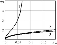
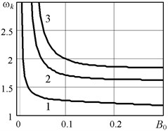
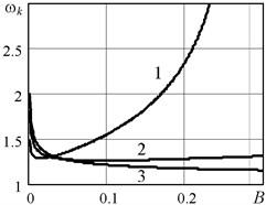
Autobalancing mode is stable when the rotor speed exceeds the boundary speed : . Fig. 2 shows graphs of the boundary speed depending on the parameters of rotor and autobalancer. Calculation results are presented in a dimensionless form using relative mechanical system parameters:
Numerical analysis was performed using the exact solution Eq. (3) with the following basic values of the parameters: 0,1; 0,01; 0,02; 0. Basic values correspond to curves No. 1 in Fig. 2. The ranges of parameters variation: 0,001…0,3; 0,001…0,2; 0,001…0,3. Specified parameter base values correspond to their critical values (which follow from the Eq. (4)), similitude criterias and boundary speed of rotation: 0,080; 0,0071; 0,283; 0,125; 0,2; 1,55.
Fig. 2The boundary of autobalancing stability ωk as a function of rotor and autobalancer parameters: a) B= 0,1; B01= 0,02; B02= 0,1; B03= 0,2; b) B= 0,1; nμ1= 0,01; nμ2= 0,1; nμ3= 0,2; c) nμ= 0,01; B01= 0,02; B02= 0,1; B03= 0,2
a)
b)
c)
5. Conclusions
Performed analysis allowed to find some features of the system parameters impact on the autobalancing stability of the mechanical system “Jeffcott rotor – multi-bodies autobalancer”. The obtained analytical expressions Eqs. (3-6) and plots in Fig. 2 let us to make the following conclusions.
1. This mechanical system allows to obtain the exact solution, which makes it possible in explicit analytic form to determine the number and value of boundary of autobalancing stability, that is the boundary rotor speeds. This exact solution corresponds to special geometrical position of the compensating bodies in ABD, which, however, is the most important case for the practical ensuring of the operational stability of the autobalancing.
2. To ensure reliable stability it should reduce the total mass of compensating bodies in ABD and increase the level of internal damping () in the ABD, that follows from Eqs. (4), (5) and Fig. 2(a), (b). There is the maximum allowable value and the largest rotor unbalance, which can be stably eliminated by autobalancer. The value is determined by the Eq. (4). When stable autobalancing of the rotor is not possible at any speeds of rotation and system parameters.
3. The external rotor damping can both stabilize or destabilize the system, as seen from the plots in Fig. 2(c). This non-trivial property of mechanical system is consequence of the fact that in considered complex system all possible kinds of forces are acting at the same time: inertia forces, positional conservative and non-conservative forces, damping forces and gyroscopic forces. The presence of these kinds of forces follows from consideration of symmetric and skew-symmetric components in the matrices , , of the motion Eq. (1).
4. Proposed necessary condition for the stability of rotor autobalancing Eq. (4) gives us clear information about the influence of system parameters on the effectiveness of autobalancer. This condition is formulated on the basis of the exact Eq. (3) and approximate Eq. (5) solutions of problem.
5. The proposed similitude criteria Eq. (6) show the fundamental properties of the considered mechanical system.
Thus, the results obtained in this work, develop existing theory of rotating machinery autobalancing and will be useful to make reasonable choices of the autobalancer parameters values at stages of their design, manufacture and operation.
References
-
Nesterenko V. P. Avtomaticheskaya Balansirovka Rotorov Priborov i Mashin so Mnogimi Stepenyami Svobody (Automatic Balancing of Rotor of Devices and Machines with Many Degrees of Freedom). Tomsk University Publishing, Tomsk, 1985, p. 84, (in Russian).
-
Fіlіmonіhіn G. B. Zrіvnovazhennya і Vіbrozahist Rotorіv Avtobalansirami z Tverdimi Koriguval’nimi Vantazhami (Balancing and Vibration Protection of Rotors by Autobalancers with Solid Corrective Weights). Kirovograd, KNT, p. 352, (in Ukrainian).
-
Gorbenko A. N. On the stability of self-balancing of a rotor with the help of balls. Strength of Materials, http://dx.doi.org/10.1023/A:1024621023821, Vol. 35, Issue 3, 2003, p. 305-312.
-
Green K., Champneys A. R., Friswell M. I., Munoz A. M. Investigation of a multi-ball, automatic dynamic balancing mechanisms for eccentric rotors. Philosophical Transactions of the Royal Society A, http://dx.doi.org/10.1098/rsta.2007.2123, Vol. 366, 2008, p. 705-728.
-
Bykov V. G. Auto-balancing of a rotor with an orthotropic elastic shaft. Journal of Applied Mathematics and Mechanics (English translation of Prikladnaya Matematika i Mekhanika), http://dx.doi.org/10.1016/j.jappmathmech.2013.11.005, Vol. 77, Issue 4, 2013, p. 369-379.
-
Gorbenko A. N. Analytical assessment of operating stability for rotor self-balancing based on the exact solution of the partial problem. Internal Combustion Engines: NTU “HPI”, http://www.nbuv.gov.ua/old_jrn/natural/Dvs/2009_2.pdf, Vol. 2, 2009, p. 109-114., (in Russian).
-
Gorbenko A. N. Change of borders of stability of autobalancing of rotor by balls in process of exploitation. Aviacionno-Kosmicheskaya Tekhnika i Tekhnologiya (Aerospace Technique and Technology), http://gorbenko-a-n.narod.ru, Vol. 8, Issue 55, 2008, p. 156-159, (in Russian).
-
Gorbenko A. N. The general structure of the movement equations of rotor machines with the autobalancer of passive type. Aviacionno-Kosmicheskaya Tekhnika i Tekhnologiya (Aerospace Technique and Technology), http://nbuv.gov.ua/j-pdf/aktit_2011_8_16.pdf, Vol. 8, Issue 85, 2011, p. 71-76, (in Russian).
About this article

