Abstract
This paper investigates the quality of communication in wireless networks and connection quality evaluation on the basic parameters of indoor and outdoor applications with produced experimental data. The analysis of the influence of radio waves propagation conditions of in the wireless communication networks were performed at the different types of medium. Comparison of the radio waves propagation indoors and outdoors has been done. Also, the effect of the obstacles of various materials on radio propagation was performed.
1. Introduction
Modern radio technical aids enable to simplify data transmission by using low-cost microprocessors in many control and management systems, including, household purposes. Works [1, 2] presents how information transfer occurs in daily life, housing services and utilities on the ZigBee network. However, to obtain an accurate estimate on research of signal propagation indoors, it is necessary to consider specific classes of a room design. The paper presents the results of experiments on research of a communication quality indoors with different obstacles.
To solve this problem experiments were carried out at the MSP laboratory facilities (two wireless modules: MSP-EXP430F6137R4 – the basic board with microcontroller CC430F6137 and MSP-EXP430F5137R4 rebroadcasting board with microcontroller CC430F5137 on a frequency of 433 MHz). According to the theory of the design of experiments [3] for ensuring accuracy of measurement with an admissible error 0,5 %, with probability distribution 99 % the number of required measurements is determined by the Eq. (1):
According to the standard table the value of Student's distribution coefficient for probability distribution 0,99 is 2.58. Then obtained number of required measurements 30. Therefore, it has to be carried out 30 measurements in each experiment. By received results following have been calculated: average mean , dispersion and average quadratic deviation .
Modules (transmitter-receiver) are located at the height of 1.15 meters. Experiments were carried out at the same conditions. Experimental conditions:
1. Signal propagation at radio-optical line of distance.
2. Signal propagation in a free space.
3. Signal propagation indoors with stationary obstacles.
4. Signal propagation with different types of obstacles.
2. 1st experiment. Signal propagation at radio-optical line of distance
For carrying out the experiment transmitter position has been fixed, the receiver is moved along a straight line. Experiment repeated 30 times after each 1-2 minutes.
As a result of data processing the following results are received and presented in Table 1.
Table 1Distribution of a radio signal within direct visibility
Distance, m | |||
1 | –51,7 | 0,0648 | 0,2545 |
2 | –62,8 | 0,00658 | 0,0811 |
6 | –65,9 | 0,00239 | 0,0488 |
10 | –75,5 | 0,00808 | 0,0898 |
14 | –80,4 | 0,081087 | 0,2847 |
22 | –82,7 | 0,0489 | 0,2211 |
30 | –83,9 | 0,06204 | 0,2490 |
40 | –85,5 | 0,04774 | 0,2184 |
50 | –90.3 | 0,00631 | 0,0794 |
60 | –102,1 | 0,0516 | 0,2271 |
74 | –103,3 | 0,0029 | 0,0538 |
Table 1 shows that the signal weakens monotonously according to the theory [7, 8]. The reason of that is not only geometrical parameters of the building, but also a low power of the transmitter and strong weakening of a signal through obstacles. The presence of walls, partitions, furniture, people and other objects in the building creates a difficult propagation medium. The main effect observed radio wave propagation indoors is multipathing which is caused by repeated reflections of radio waves from walls and other objects, diffraction at numerous sharp edges of the objects located in the room and radio scattering. These effects create the difficult interferential structure of the electromagnetic field which is change strongly when people and other objects moving [11].
3. 2nd experiment. Signal propagation in a free space
The experiment was carried out on the street. It can be seen from table 2 that signal decays when the distance between receiver and transmitter increases [9]. There are problems associated with the influence of the various signal parameters such as distance, multipath, reflection, and others during the radio signal propagation in free space [11]. The signal level at the reception is determined by signal-carrier frequency and distance. Apart from the obvious tendency of signal attenuation, there are rapid fluctuations in power levels, which depend on the distance. When the signal propagates in free space, the received power is inversely proportional to the square of the distance to the transferring antenna [10]. The phenomena of signal depression are observed. For some values of signal distance from antennas, they pass different path, arrive at the receiving antenna on the opposite phase that can reduce power. For some other values of distance, the incoming signals are added that increases the signal level.
Table 2Distribution of a radio signal in free space
Distance, m | |||
1 | –57,4 | 0,0169 | 0,13 |
2 | –59,7 | 0,00032 | 0,0178 |
6 | –70,6 | 0,00068 | 0,0260 |
10 | –79,7 | 0,00648 | 0,0804 |
14 | –81,9 | 0,00658 | 0,0811 |
22 | –85 | 0,0023 | 0,0479 |
30 | –88,2 | 0,004498 | 0,0670 |
40 | –94,03 | 0,0022 | 0,0469 |
50 | –96,69 | 0,00297 | 0,0544 |
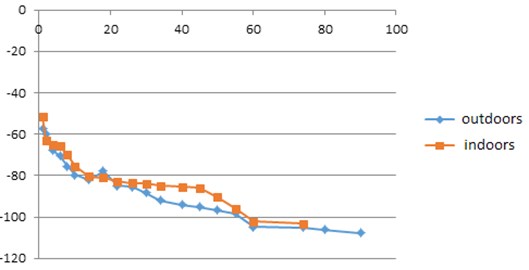
At signal propagation indoors it meets on the way artificial barriers as furniture, walls and various stands. At signal propagation outdoors it meets natural obstacles as mountains, trees, lawn and asphalt. Thus, any more or less wide object can be an obstacle. There are several possible options depending on the sizes of obstacle: signal might bend around an obstacle, or behind the object the parietal zone with very low level signal arises, or no signal at all. According to the experiment results can be seen that signal propagation outdoors worse than indoors. It is explained by negative or destructive multipath propagation [10]. There is a decrease of signal strength, i.e. reduction of amplitude. When multiple radio signals arrive at the receiver at the same time and are out of phase with a base signal, the result is a decrease of the signal level. It is assumed that the phenomena of other signals influencing became much more powerful. At signal propagation indoors some incrementation noticed that is an increase in signal strength and in amplitude compared with signal propagation outdoors for the MSP430RF4 board (Fig. 1). It is positive or constructive multipath signal propagation. When multiple radio signals arrive to the receiver at the same time and are in a phase or with a small misphasing in relation to a base signal, the result is signal strength and amplitude increasing. A small difference in phases from 0 degrees to 120 degrees will cause a signal level gain [11].
Fig. 1The schedule of the dependence of signal power to distance at radio-optical line of distance
4. 3rd experiment. Signal propagation indoors with stationary obstacles
Conditions of radio wave propagation are more diverse indoors, in the area of the complicated visibility. Concrete walls (M350 brands) the with thickness of 10-15 cm between rooms are stationary obstacles. Rigid obstacles (part of the building structure) also affect to radio signal propagation [4]. From Table 3 it is shown that signal attenuation occurs with the receiver distance increasing from the transmitter.
Table 3Passing of a radio signal through concrete walls
Distance, m | |||
4 | –63,4 | 0,0346 | 0,186 |
6 | –64,1 | 0,0085 | 0,0921 |
10 | –75,1 | 0,0079 | 0,088 |
12 | –75,5 | 0,0202 | 0,1421 |
20 | –98,2 | 0,0042 | 0,0648 |
In the analysis of experimental results, it is necessary to take into account signal reflection on walls at normal incidence of a radio wave and “focusing” of the wave flow due to the refraction [5]. When a radio waves fall at the interface of two medium with different refractive indices the part of a wave is reflected back. Coefficients of reflection and transmission (by power) are determined by Eq. (2) and Eq. (3):
where , – refractive index of a medium [6]. In calculations can take 1 (air), 1,9 – 2 (wall), then about 10 % of a signal are reflected from a wall. Neglect of this effect leads to an overestimation of the attenuation of about 0.5 dB.
The second factor – “focusing” of a radio wave due to refraction, which leads to an underestimation of the absorption amount as illustrated in Fig. 3. The spherical radio wave extending from point upon transition from the medium with refractive index to the medium with refractive index and again to the medium with an index “nestles” from an axis .
Fig. 2Radio wave narrowing (“focusing”) when passing through a wall
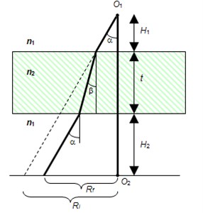
Assume that the receiver settles down at the point. If there is no wall, then the radius of the cone with an angle and with a vertex at the point at a distance is . If there is a wall with the radius of a cone is . Thus, in a first approximation, transmitter energy in this cone in the first case is distributed on the , and in the second case . Then relative signal amplification at the receiver (in the absence of absorption in a wall) is shown in the Eq. (4):
where . Along an axis amplification is Eq. (5):
Amplification is maximal as a result of refraction, if the receiver and transmitter fasten down to the wall , 2 (3 dB). With the increase of distance of the receiver and transmitter to the wall this effect rapidly decreases (Fig. 3).
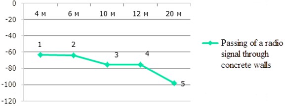
Taking into account the considered factors, measurement results of attenuation at 1-5 positions as following:
1. 0,7±1 dB, (position 1 and 2).
2. Concrete wall with the thickness of 10 cm, 12,1±1 dB, (position 1 and 3, 6 m).
3. 0,4±1 dB, (position 3 and 4).
4. Concrete wall with the thickness of 10 cm of 22,7±1 dB, (position 3 and 5, 10 m).
Thus, during experiments, it was determined that if the receiver and transmitter installed at a distance of several centimeters from the wall (on opposite sides) the concrete wall makes least of all attenuation – about 0,7 dB with the refraction. The distance between receiver and transmitter affected to the signal attenuation [12].
Fig. 3Signal power – distance graph, considering obstacles 1
5. 4th experiment. Signal propagation with different types of obstacles
The experiment was performed at the laboratory stand. For experiment simulation scaled-down model with different types of obstacles is offered. To perform the experiment positions of transmitter and receiver have been recorded. Wave guide length is 1,5 m. Measurements were repeated 30 times in 1-2 minutes, considering 4 types of materials on the path of radio signal propagation (Fig. 4). There is a foil (with the thickness of 10 mm), gypsum cardboard (with the thickness of 10 mm), chipboards (with the thickness of 8 mm) and ceramics (with the thickness of 5 mm). Experimental conditions:
1. The transmitter and the receiver were installed in a wave guide with a length 1,5 m without obstacles.
2. Two foils with the thickness of 10 mm were installed on the path of radio signal propagation in a wave guide: first is close to the receiver and second is close to the transmitter.
3. Two gypsum cardboards with the thickness of 10 mm were installed on the path of radio signal propagation in a wave guide: first is close to the receiver and second is close to the transmitter.
4. Two chipboards with the thickness of 8 mm were installed on the path of radio signal propagation in a wave guide: first is close to the receiver and second is close to the transmitter.
5. Two ceramics with the thickness of 5 mm were installed on the path of radio signal propagation in a wave guide: first is close to the receiver and second is close to the transmitter.
As a result of data processing the following results which are presented in table 4 are received.
Table 4Distribution of a radio signal through different types of obstacles
No. experiment | 1 | 2 | 3 | 4 | 5 |
M[X] | –46,79 | –49,02 | –49,72 | –50,46 | –52,89 |
D[X] | 0,10201 | 0,00698 | 0,01922 | 0,00032 | 0,0803 |
σ(x) | 0,319 | 0,0835 | 0,1386 | 0,0178 | 0,2833 |
Table 5Relative values of power reduction
Type of obstacles | Foil | Gypsum cardboard | WSP | Ceramics |
Power difference (power reference) [dBm] | –2,23 | –2,93 | –3,67 | –6,1 |
Thickness [mm] | 0,01 | 10 | 8 | 5 |
Relative size [W/m] | 59,8 | 0,0509 | 0,043 | 0,0245 |
Radio waves are attenuated or absorbed by material when passed through objects. Radio waves lose the part of energy due to absorption when there are passing through materials [12]. Attenuation force depends on:
− thickness,
− structures/ material properties,
− material density.
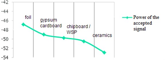
Table 5 and Fig. 4 show that the presence of gypsum board and chipboard give approximately the same effect on radio propagation in the waveguide. And the obstacle as ceramics is sharply worsened a signal to 6,1 dBm.
One of the important parameters is signal power. The power accepted at a certain distance from the transferring antenna can be expressed through the power measured at any standard distance i.e. through power reference [12]. Table 5 shows the relative values of power reduction of the accepted signal were found considering the power reference of a signal without obstacles.
Fig. 4Dependence graph of signal power to an obstacle type
6. Conclusions
From the experiment results, the dependence of signal power to distance between the receiver and the transmitter at the radio-optical line was received. At distance of 10 m reduction of signal power by 4,2 dBm, on 20 meters 3,2 dBm, on 30 meters 4,3 dBm, on 60 meters about 3 dBm are observed. Also as a result of the experiment it was revealed that while wireless transmission of text and numerical data between MSP430RF4 TI boards the radio signal propagates indoors better than outdoors.
It was revealed that signal attenuation occurs when a distance from the receiver to the transmitter increases. Concrete walls do not have a significant impact on the transmission of information between MSP430RF4 boards, as at positions 1 and 2 signal attenuation is 0,7 dBm and at positions 3 and 4 signal attenuation is 0,4 dBm. At the maximum distance recommended by the manufacturer – 100 meters, the radio signal has sharply weakened to –98 dBm, that is at this distance transfer of a text or numerical package of information is impossible.
Also, the influence of different types of obstacles on the radio signal propagation was estimated. Considering the relative size of the accepted signal power, it can be concluded that the presence of gypsum cardboard and chipboard approximately equally affected to radio signal propagation in a wave guide. The influence of the metal obstacle imitated by a thin leaf of a foil, signal attenuation through obstacles is reflected by the weakening of a signal up to its disappearance, which is characterized by signal power. The ceramic obstacle has a very small effect on the power of the transmitted signal, that it is reflected in graphs.
Recommendations: investigation of the microcontrollers MSP showed that they are recommended for text and digital information transmission at distance no more than 90 meters indoors which can be used for systems as automation systems for “Smart House”, automation systems for housing services and utilities or automated control systems of buildings.
References
-
Jun W., Min C., Victor C., Leung M. Forming priority based and energy balanced ZigBee networks – a pricing approach. Telecommunication Systems, 2011.
-
Baronti P., Chessa S., Gotta A, Fun H.,Pillai P. Wireless sensor networks: a survey on the state of the art and the 802.15.4 and ZigBee standards. Journal of Computer Communications, Vol. 30, Issue 7, 2007, p. 1655-1695.
-
Krasovskii G., Filaretov G. Experimental Design. BSU, Minsk, 1982.
-
http://beton224723.ru/info-marcs, 2015.
-
Ryzhov A., Lazarev V., Mochseni T., Nikerov D., Andreev I., Dmitriev A., Chubinskiy N. The Weakening of the Ultrawideband Chaotic 3-5 GHz Signal While It Passes Through the Building Walls. Moscow, 2012.
-
Sivuhin D., Sivuhin D. The General Course of Physics. Optics. 3rd Edition, Phyzmathlit, Moscow, 2005.
-
Multipath Distribution of Radiowaves. Systems and Networks, http://systemseti.com/CCPO/403.html, 2015.
-
Gavrilenko V., Yashnov V. The Transmission of Information Via Wireless Networks in Varying Terrain. Nizhny Novgorod, 2007.
-
Yelkin M. Assessment of the Suitability of the Radio Outdoors. The electronic newspaper “Security Systems” http://www.secuteck.ru/articles2/firesec/ocenka-prigodnosti-radiolinii-vne-pomeshenii, 2015.
-
Stalling W. Wireless Communications and Networking. Pearson Education, 2nd Edition, USA, 2004.
-
Uysal M. Cooperative Communications for Improved Wireless Network Transmission. Information Science Reference, 2009.
-
Tassiulas L. Scheduling and performance limits of networks with constantly changing topology. IEEE Transactions on Information Theory, Vol. 43, Issue 3, 1997, p. 1067-1073.
About this article

