Abstract
The model of SIMO or SISO is usually used in the traditional vibration testing while the test item is always excited by multiple excitations in the field. The dynamic characteristics of structure (such as resonant frequency, mode shapes and modal damping) which will provide the basis for further analysis are obtained by vibration testing. Since the shaker needs to be mechanically attached to the structure under test, it is nearly inevitable that some sort of interaction will occur between them. It means that the traditional vibration testing or simulation don't have the ability to completely replicate the environment of test structure in the field which will lead to inaccurate results or even incorrect results. This paper offers differences between traditional SIMO vibration testing and MIMO vibration testing and presents some advantage of MIMO vibration testing which will distinctly improve the situation in laboratory and make boundary in the laboratory more similar to the environment in the field. Compared to traditional SIMO vibration testing, the MIMO vibration testing in the laboratory not only can significantly minimize the phenomenon of drops in the excitation forces close to resonant frequencies but also can replicate the boundary situations of the test item in the field.
1. Introduction
Among the available techniques to excite a structure in vibration testing, shaker is probably the most popular device, thanks to its flexibility and capability to reproduce a wide range of excitation signals such as periodic, random. Since the shaker needs to be mechanically attached to the structure under test, it is nearly inevitable that some sort of interaction will occur between them. The causes and effects of this interaction have been an issue for experimentalists since the very beginning of modal analysis and is still a relevant research topic, in both open-loop and in closed-loop shaker testing. The dynamic characteristics of structure (such as resonant frequency, mode shapes and modal damping) which will provide the basis for further analysis are obtained by experimental vibration testing [1, 2]. However, the model of SIMO or SISO is usually used in the traditional vibration testing while the test item is always excited by multiple excitations in the field.
The traditional test or simulation in laboratory just use single or related signal as excitation. Single or related shaker can give the test structure sufficient excitation in functional tests or degradation tests of product under some circumstances. Nevertheless, it is difficult to find an object of vibration caused by a single vibratory source. Almost every test structure in field is excited by even more than two excitations. So, if we want to simulate the same condition of the test structure in the laboratory compared to field condition, the most important thing should be improved is to adopt multiple-input and multiple-out testing system which could provide multiple excitations simultaneously. The traditional vibration testing (SIMO) measurement techniques are a well-proven and well-established method. But there are many drawbacks. Paulo Sergio Varoto and Leopoldo Pisanelli Rodrigues de Oliveira presented a study on the force drop off phenomenon in shaker [3]. In particular, Oliveira and Varoto presented a study on [4] this matter paying special attention to the force drop-off phenomenon and making a brief review of most of the references cited above. Also, Lang [5] approached the subject from the point of view of the shaker’s performance and Peres et al [6] presented several practical aspects on setting up the excitation device. The versatility of shakers can also be assessed in less conventional multiple input devices such as 6-DoF exciters [7] often used in environmental and reliability testing. M. A. Peres1 and C. Kallmeyer1 had the further study about advantages of Multiple-Input Multiple-Output (MIMO) testing using low level excitation systems [8].
2. Theory
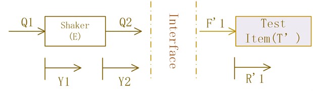
The key of laboratorial test is to replicate the boundary of the field condition. It is assumed that the structure is linear and ignoring the external force. The field situation is described in Fig. 1 and the laboratorial condition is shown in Fig. 2 [9]. In the Fig. 1, the excitation has two motions ( and ) caused by the excitation forces ( and ), and the test item has a motion () according to the excitation forces (). In order to keep the same boundary, the laboratory situation has similar environment. In the Fig. 2, the shaker has two motions ( and ) caused by the excitation forces ( and ), and the test item in the testing has a motion () according to the excitation forces (). Subscript 1 is used to denote the interface (connection) point, while subscript 2 is used to denote the non-interface point.
Fig. 1Schematic depicting field environment
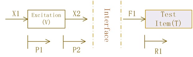
Fig. 2Schematic depicting laboratory environment
The motion of excitation in the field is described by:
where: is the motion frequency spectrum in terms of either displacement, velocity, or acceleration; is the excitation’s input-output FRF matrix in terms of either receptance, mobility, or acceleration depending on being displacement, velocity, or acceleration; is the input force frequency spectrum.
The motion of shaker in the laboratory is similar to the motion of excitation in the form. The key in test is to replicate the boundary (make ).
The test item should have to be described by a field model and a laboratory model since these structure can have slightly different characteristics due to manufacturing. The equation in the field environment is:
where: is the motion frequency spectrum in terms of either displacement, velocity, or acceleration; is the test item’s input-output FRF matrix in terms of either receptance, mobility, or acceleration depending on being displacement, velocity, or acceleration; is the input force frequency spectrum.
The equation in the laboratory environment is similar in the form. According to Newton’s third law, there is an implicit condition (, ). However, there are more than one mechanical connections to every objection in the field environment actually so that the variables (, ,…, , ) are vectors.
3. Difference to the traditional testing
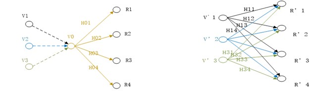
The relationship between laboratory and field environment has been presented above. Traditional method always combines all forces together as a excitation shown as left side in Fig. 3. But the truly situation is depicted as right side in Fig. 3. In traditional testing, the responses (, , , ) are caused by excitation (). But the responses (, , , ) in field are caused by excitations (, , ). In order to control the input, the excitation () in the laboratory is combined from the variables (, , , which is set according to the excitations (, , ) in the field).
Fig. 3Difference between traditional testing and field environment
Traditional laboratory vibratory testing excitation system is shown as Fig. 4, which is the model of SIMO. Compared to Traditional system, the main difference of multiple-input and Multiple-output (MIMO) vibratory testing excitation system shown in Fig. 5 is that more than one shakers are working simultaneously.
Compared to the traditional vibration testing, multiple mechanical connections on the test structure in MIMO model will have the distinctly different dynamic characteristics.
Fig. 4Traditional laboratory vibratory testing excitation system
4. Effect of the technology of multiple-input and multiple-output testing
In order to demonstrate the effect of technology of multiple-input and multiple-output to vibratory testing, the structure is abstracted as a model shown in the Fig. 6. The system under study is a 4 Dof mass-spring-damper (see Table 1 for physical properties) which is excited by two identical shakers (Fig. 6).
Fig. 5Multiple-input and Multiple-output vibratory testing excitation system
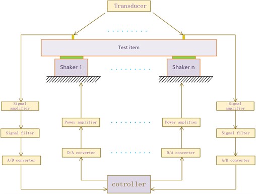
Fig. 64 Dof mechanical system excited by two shakers
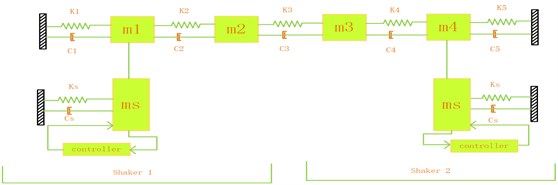
Table 1Basic size and style requirements
Parameter | Values | Unit |
10 | kg | |
3 | kg | |
8 | kg | |
5 | kg | |
50 | kg | |
, , , | 400000 | N/m |
500000 | N/m | |
, , , | 5 | Ns/m |
10 | Ns/m |
In the following section, we will discuss the effect of multiple-input and multiple-output vibratory testing to general response. The system that is displayed in the Fig. 6 will also be studied. The response on will be taken into consideration. In order to simplify the counting process, we assume that the power spectrum density (PSD) of input excitation is constant so that the response equals the production of input excitation and the FRF. The traditional SIMO testing has only one excitation. We have to combine many inputs into a excitation when the test structure is excited by multiple forces in the field. The inputs on and in field are assumed to be the unit dimension. Only one input is generally taken into consideration in laboratory. When we just guarantee the input in simulation on is the same as the excitation in the field and the input on is ignored, the response on is revealed as H12 in Fig. 7. While the both inputs are considered, the response on is shown great differently as red line in Fig. 7. Fig. 8 shows the differences between two situations in the form of conventional coordinates.
Fig. 7Only consideration of input on m1
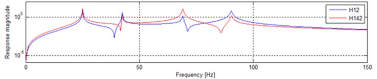
Fig. 8Only consideration of input on m1
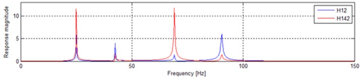
The input on is completely neglected when we only consider the input on m1and information of input on will be absolutely missed. The only way in the traditional vibratory testing can make up for the deficiency is to put the two inputs together. The input on m1 becomes into two times as is shown in Fig. 9 (2H12). H142 in Fig. 9 is the same as above. The difference in the form of conventional coordinates is shown in Fig. 10. It is easy to find the significant distinctions between 2H12 and H142.
Fig. 9Only consideration of input on m1
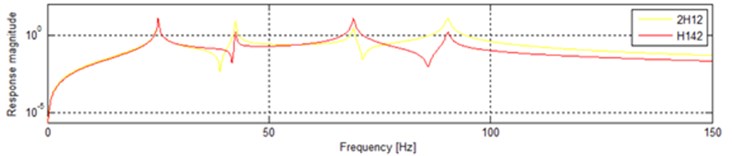
Fig. 10Combine the input on m4 into the input on m1
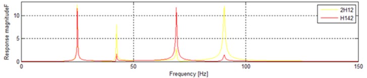
Fig. 11Combine the input on m4 into the input on m1
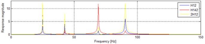
In Fig. 11, H10 is the response of situation that the input on m1 is only considered. And the 2H12 is the response of situation that the input on is combined into the input on . While the H142 show us the response when the input on m1 and the input on is considered separately. It is obvious that significant distinctions occur in three situations.
5. Conclusions
Multiple-Input Multiple-Output (MIMO) measurement techniques are a well-proven and well-established method for collecting FRF data sets. Despite that, the idea of using multi-references and multiple shakers can be intimidating for an inexperienced modal test engineer. MIMO methods offer some distinct advantages for vibration testing. The MIMO vibration testing in the laboratory can accurately replicate the boundary situations of the test item in the field.
References
-
Migdalovici M., Sireteanu T., Videa E. M. Control of vibration of transmission lines. International Journal of Acoustics and Vibrations, Vol. 15, Issue 2, 2010, p. 65-71.
-
Elliott S. J. Active control in vehicles and in the inner ear: a review. International Journal of Acoustics and Vibrations, Vol. 14, Issue 4, 2009, p. 212-219.
-
Varoto Paulo Sergio, de Oliveira Leopoldo Pisanelli Rodrigues On the force drop off phenomenon in shaker testing in experimental modal analysis. Shock and Vibration, Vol. 9, 2002, p. 165-175.
-
Varoto P. S., de Oliveira L. P. R. On the force drop-off phenomenon in shaker testing in experimental modal analysis. Journal of Shock and Vibration Vol. 9, Issues 4-5, 2002, p. 165-175.
-
Lang G. F. Understanding the physics of electrodynamic shaker performance. Sound and Vibration, Vol. 35, Issue 10, 2001, p. 24-33.
-
Peres M. A., Bono R. W., Brown D. L. Practical aspects of shaker measurements for modal testing. Proceedings of ISMA2010, Leuven, Belgium 2010, p. 1-12.
-
De Coninck F., Vaes D., Swevers J., Desmet W., Sas P. Vehicle suspension and structure borne road noise testing on a 6-DOF high frequency shaker table: first outlines. Proceedings of the 30th Fisita World Automotive Congress, Barcelona, Spain, 2004.
-
Peres M. A., Kallmeyer C., Witter M. C. Advantages of multiple-input multiple-output testing. Sound and Vibration, Vol. 49, Issue 8, 2015, p. 8-12.
-
McConnell Kenneth G. Vibration Testing Theory and Practice. John Wiley and Sons, New York, 1995, p. 535-599.
-
Shih C. Y., Tsuei Y. G., Allemang R. J., Brown D. L. A frequency domain global parameter estimation method for multiple reference frequency response measurements. Mechanical Systems and Signal Processing, Vol. 2, Issue 4, 1988, p. 349-365.
-
Lang G. F., Burroughs G., Carmichael G. Random testing to new limits. Sound and Vibration, Vol. 43, Issue 2, 2009, p. 5-9.
-
Tomlinson G. R. Force distortion in resonance testing of structures with electrodynamic vibration exciters. Journal of Sound and Vibration, Vol. 63, Issue 3, 1979, p. 337-350.
About this article

