Abstract
Fast methods to identification and recognition of structural defects are important issues for the industry. In recent years, a growing interest has been on quick structural inspection to significantly reduce inspection’s cost and time, while minimizing the number of Non-Destructive Testing (NDT). Investigations on damage detection methods based on vibration monitoring have been developed in the last decade. This paper presents a study on Inner Product Vector (IPV) method. The IPV method is a new vibration based damage detection technique. In this method vibration responses are measured before and after damage occurrence. The vibration responses include the time domain acceleration (or displacement or velocity). The IPV method has the potential to significantly reduce costs by minimizing the need for NDT methods. For damage detection via the IPV method, a threshold should be selected for classifying the damaged and undamaged sections of a structure. Proper determination of the threshold value requires selection of Confidence Interval Factor (CIF). In this study, a new algorithm for the IPV method is suggested in which a new optimized model for damage detection is presented. Aforementioned optimized model can provide an accurate value for the CIF. To ascertain the exact CIF, the damage detection method is simulated. An accurate threshold makes the IPV method capable to accurately detect damages. The method has been verified by means of an FEM model as well as an experimental case study. The results show that the optimization process can be used as a reference to ascertain value for the CIF. The IPV method can be used as a Structural Health Monitoring (SHM) method, but it’s necessary to optimize the IPV method for each sample.
1. Introduction
Fast methods to identification and recognition the structural defects are important issues for the industry. Non-Destructive Testing (NDT) methods are used traditionally for identifying defects, each one having advantages and disadvantages, making it more or less appropriate for a given application. Some of NDT methods are radiography, ultrasonic testing, penetrant testing, magnetic testing, eddy current method, and time of flight diffraction (TOFD) and phased array. Limited access, time-consuming, expensive and complex structure configurations restricts the type of indirect or direct NDT methodologies which can be applied by inspectors. In recent years, a growing interest was on quick structural inspection to significantly reduce inspection’s cost and time, while minimizing the number of Non-Destructive Testing (NDT). This paper presents a study on a new Vibration-Based Damage Detection technique (VBDD). Investigations on VBDD methods have been developed in the last decade. In recent years, research on VBDD methods has become very popular. Previous studies on VBDD methods indicate that structural damage is detected by measuring dynamic characteristics related to vibration such as, natural frequency [1], mode shape [2], time-domain response [3], frequency response functions [5, 6], power spectral density [7], transmissibility functions [8], coherence functions [9], correlation functions [10-12], etc.
In 2010, the IPV-based structural damage detection method for the first time was presented by Le Wang et al. [13]. The IPV method is a new vibration based damage detection technique. In this method, cross correlation functions between vibration responses under band pass white noise excitation is used for damage detection [14]. The IPV method is invaluable inspection method during the manufacturing, construction and the operation. The IPV method has the potential that could lead to significantly lower costs by minimizing the need for NDT methods. Previous studies indicate that the IPV method is able to detect surface damages [12-15]. Le Wang et al. [13], studied a honeycomb sandwich composite beam with a single damage and showed that the IPV method is able to detect damage. Also, they indicate that the IPV method is able to detect damage in the 8 storey shear frame structure [13]. Current studies indicate that the IPV method is able to detect internal damages; Lack of Root Penetration (LOP) and Lack of side-wall fusion (LOSWF) in a butt weld and lamination defect in AL2024-T3 plate, as well. [16, 17]. One of the first examples of the practical application of the IPV-based structural damage detection method is presented by Le Wang et al. [13]. They have studied to detect the damage occurring on the interface between the stringers and the aircraft stiffened panel using the IPV method. In this work, four different structure states with different bolt loosenings are studied. The results indicate that the IPV method is able to correctly locate the bolt loosening location in the aircraft stiffened panel. Structural damage detection using the IPV method damage is detected by the local maximum of the damage index. For structural damage detection by the IPV method is needed to select a threshold for separating the damaged and undamaged structure [13-15]. Application of the IPV method requires the selection of an appropriate Confidence Interval Factor (CIF) to determine the threshold value. In previous studies, the CIF achieved with experimental test on a similar structure [12-15]. There are many limitations in experimental determination of CIF. In this study, a new algorithm for the IPV method is suggested to provide a new optimized model for damage detection. Optimized IPV-based damage detection can provide an accurate value for the CIF. FE model of a damaged pipe has been used as the numerical case study. The FE model is constructed in ABAQUS; while MATLAB is employed to calculate the numerical routines. In order to verify and validate the method, the results of the simulated IPV model are compared with an experimental test result.
The remainder of the paper is organized as into six sections: Section 2 describes theory of IPV and damage index using IPV. In Section 3, IPV-based structural damage detection will be discussed. Optimization theory of IPV is presented in Section 4. Verification and validation of optimized model for the IPV method will be discussed in Section 5; the conclusion is reported in Section 6.
2. Theory of IPV and damage index using IPV
La Wang et al. [15] indicate that the IPV is obtained by one row (or column) of the dimensional matrix. The dimensional matrix can be obtained considering the cross correlation function between all combinations of response measurement points 1, 2,…, as when the time lag 0. The IPV can be obtained by calculating the displacement, velocity and acceleration response, respectively, are defined as: [13-15]:
where , and are weighting factors, and the modes in the summation for calculating IPVs are dependent on the frequency range of the band pass white noise excitation [14]. Damage caused to decrease the effect of measurement noise [14, 15], i.e. Using the difference between the IPVs of the intact and damaged structures, a local damage index is defined:
where and indicate the th element in the IPVs of the undamaged and damage structures, respectively. Then, the damage index is defined as . Structural damage detection using the IPV method damage is detected by the local maximum of the damage index. Also, it is needed to select a threshold for separating the damaged and undamaged structure. In this paper, we used the threshold that it is adopted by Le Wang et al. [15], i.e.:
where: is the mean value of (or or ), is the standard deviation of (or or ), is a coefficient corresponding to a confidence interval.
Structure is undamaged, if the elements of (or or ), fall in the region between and , the structure; otherwise, the structure is damaged. [15]
3. Damage detection process using the IPV method
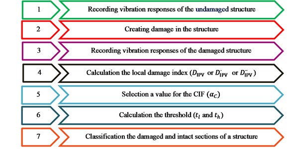
For structural damage detection using the IPV method, firstly vibration responses are measured before and after damage [15]. The vibration responses include the acceleration (or displacement or velocity) in the time domain. Then, the local damage index ( or or ) are calculated. Next, a value for the CIF should be selected to calculate the threshold. Finally, we will be able to classify the undamaged and damaged sections of a structure [15]. A typical procedure for the method is depicted as shown in Fig. 1.
Fig. 1Damage detection process using the IPV method
4. Optimization of damage detection process using the IPV method
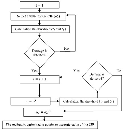
The focus of attention in this paper is on optimization of the IPV method. As shown in Eq. (5), after calculating the local damage index ( or or ), a value for the CIF should be selected to calculate the threshold. In previous studies the CIF was determined by experimental testing [13-15]. There are some drawbacks in experimental determination of the CIF such as cost, time consumption, retest restrictions and creating damage in different places of the sample. The suggested improved algorithm for the IPV method is shown in Fig. 2. It can provide an accurate value for the CIF. To ascertain the exact CIF, the damage detection method is simulated. The simulation of the IPV method can provide an accurate baseline model for damage detection. As shown in Fig. 2, selection process of the CIF is continued until achieving an appropriate threshold. An accurate CIF improves the reliability of the IPV method.
Fig. 2Optimization damage detection process using the IPV method
5. Verification and validation of optimization damage detection process using the IPV method
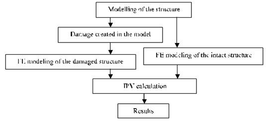
In this section, the results of the IPV on simulated model are compared with an experimental test results. In numerical study, an FE model is used to simulate the IPV method using ABAQUS. This software (Abacus/CAE 6.10-2, ©Dassault Systems, 2010) is used to model the pipe physically considering boundary conditions and respective loading conditions, to analyze the corresponding numerical model, and to obtain the vibration responses. Finally, MATLAB (MATLAB R2011a, The Math Works, and Inc.) is used to manipulate the IPV method. (See Fig. 3).
Fig. 3Damage detection process using the IPV method in simulation study
5.1. Experimental case study
As shown in Fig. 4, the pipe has a dimension of 60 cm in lengths; 1.5 cm in out diameter and 1 (mm) in wall thickness. The outer surface of the pipe is painted and 2 cm of pipe is used as a fulcrum. As shown in Fig. 1, vibration responses from the intact and damaged structure are utilized to calculate the IPVs and fulfill the damage detection. [12].
5.1.1. Recording vibration responses of the undamaged structure
For recording vibration responses of the structure is needed to excitation of sample. For damage detection using the IPV method, it requires excitation of sample at one point. In this study, a bolt has been installed on the vibration table to excite the pipe (see Fig. 5). For recording vibration responses of the undamaged structure, eight equally spaced accelerometers are affixed along the pipe. The test setup is shown in Fig. 6. Finally, vibration responses are obtained from the intact pipe.
5.1.2. Recording vibration responses of the damaged structure
First, a transverse crack was created on the outer surface of the pipe. The damage site is about 42-43 cm from the fixed-end (see Fig. 7). Finally, we obtained vibration responses (acceleration) from the damaged pipe.
5.1.3. Result of experimental test
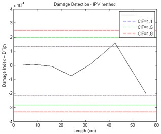
The vibration responses from the intact and damaged structure are utilized to calculate the local damage index ( or or ). Structural damage detection using the IPV method damage is detected by the local maximum of the damage index. Also, it is needed to select a threshold for separating the damaged and undamaged structure. Selection a value for the CIF is needed for calculation a threshold. The choice of CIF () seriously affects the damages detection [13-15]. In this study, the choice of CIF was based on the optimization method (see Fig. 3). Fig. 8 shows the damage detection result of the experimental test. Structure is undamaged, if the elements of (or or ), fall in the region between and ; otherwise, the structure is damaged [13- 15]. As shown in Fig. 8, if either the value of 1.5 or 1.8 selected for the CIF, the threshold would not be able to classify the damaged and intact sections of a structure. When the CIF is 1.1 the damage can be detected. As shown in Fig. 8, damage is predicted between 40 cm to 50 cm from the fixed-end of the pipe. Approximately, damage location is 41-43 cm from the fulcrum.
Fig. 4Boundary conditions in the experimental test
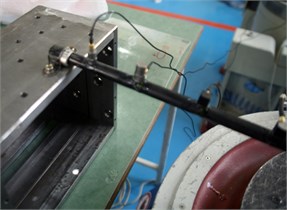
Fig. 5A bolt was installed on the vibration table for the vibrating pipe
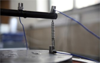
Fig. 6The experimental test setup
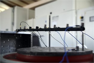
Fig. 7A transverse crack was created on the outer surface of pipe
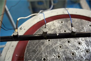
Fig. 8Damage detection results of crack transverse using acceleration responses with experimental test
5.2. Simulation study of damage detection based on IPV method in pipe
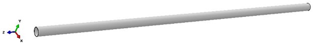
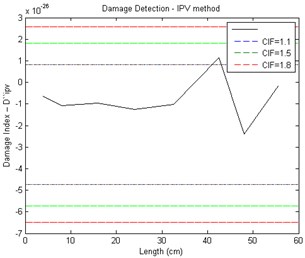
A mild steel pipe used in the experimental test were modelled through the FE software ABAQUS (see Fig. 9). The pipe is excited at one point. Vibration responses of eight nodes are obtained along the pipe with identical intervals (see Fig. 10). Then, A transverse crack was created in model similar to the experimental case (see Fig. 11). Acceleration responses of damaged pipe are recorded (see Fig. 12). Fig. 13 shows the damage detection results. Selection of CIF is based on the optimization of IPV method (see Fig. 3). As shown in Fig. 13, when the value of 1.5 or 1.8 is selected for the CIF, the threshold line doesn’t make confluence with the IPV graph; in other words, the threshold will not be able to classify the damaged and undamaged area. When the CIF is 1.1 the damage can be detected. As shown in Fig. 13, damage location is predicted between 40 cm to 50 cm from the fixed-end of the pipe. Approximately, damage location is 41.5-43 cm from the fulcrum.
Fig. 9a) A finite element model of the pipe was created using ABAQUS software, b) The boundary conditions for the experimental test
a)

b)
Fig. 10Sketch of the test setup and the undamaged pipe is excited and acceleration responses are recorded
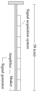
Fig. 11A crack transverse defect was created in the model
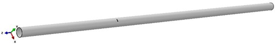
Fig. 12Sketch of the test setup and the damaged pipe is excited and acceleration responses are recorded
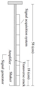
Fig. 13Damage detection results of crack transverse using acceleration responses with simulation test
5.3. Damage detection results
As shown in Figs. 8 and 13, it can be concluded that the ability of damage detection in experimental and simulation tests has been satisfactory. This experimental test demonstrates validation of the simulation and optimization process based on the IPV method used in this article. As shown in Figs. 8 and 13, the value of the CIF that was obtained by simulation study is best selection to classify the damaged and undamaged areas for experimental test. The results of the optimization process can be used as a reference for the value of the CIF. Thus, the IPV can be used as an efficient SHM method if, it is optimized for each sample.
6. Conclusions
This paper presents a study on the IPV method. This method has the potential to significantly reduce costs by minimizing the need for NDT methods, especially for inspection of a large area. In IPV-based damage detection, a threshold should be selected for classifying the damaged and undamaged sections of a structure. To determine the threshold value, a Confidence Interval Factor (CIF) should be selected in advance. The problem with this approach is in that it, the CIF was determined by experimental testing. In this study, a new technique in the IPV method is suggested, providing a new optimized model for damage detection. The proposed technique can provide an accurate value for the CIF. To ascertain the exact CIF, the damage detection method is simulated. Simulation is an effective way to optimize the IPV method, in other words, the accuracy of the IPV method can be improved by the optimized method. FE model of a damaged pipe is used for verification. In order to validate the optimization process, the results of the IPV simulation model are compared with an experimental test results. The results show that the experimental test and simulation test were able to detect the location of defects in structure. Comparison of the results showed that the value of the CIF that was obtained by simulation study is best selection to classify the damaged and undamaged areas for experimental test; moreover, the results of simulation can be used as a reference to choose a proper value for the CIF.
References
-
He K., Zhu W. D. Structural damage detection using changes in natural frequencies: theory and applications. Journal of Physics: Conference Series, Vol. 305, Issue 1, 2011, p. 012054.
-
Maia N. M. M., Silva J. M. M., Almas E. A. M. Damage detection in structures; from mode shape of frequency response function methods. Mechanical Systems and Signal Processing, Vol. 17, Issue 3, 2003, p. 489-498.
-
Cattarius J., Inman D. J. Time domain analysis for damage detection in smart structures. Mechanical Systems and Signal Processing, Vol. 11, Issue 3, 1997, p. 409-423.
-
Kuroiwa T., Iemura H. Vibration based damage detection using time series analysis. The 14th World Conference on Earthquake Engineering, Beijing, China, 2008.
-
Guo N., Yang Z., Jia Y., Wang L. Model updating using correlation analysis of strain frequency response function. Mechanical Systems and Signal Processing, Vols. 70-71, 2016, p. 284-299.
-
Salehi M., Ziaei-Rad S., Ghayour M., Vaziri-Zanjani M. A. A Structural damage detection technique based on measured frequency response functions. Contemporary Engineering Sciences, Vol. 3, Issue 5, 2010, p. 215-226.
-
Zheng Z. D., Lu Z. R., Chen W. H., Liu J. K. Structural damage identification based on power spectral density sensitivity analysis of dynamic responses. Computers and Structures, Vol. 146, 2014, p. 176-184, https://doi.org/10.1016/j.compstruc.2014.10.011.
-
Zhu D., Yi X., Wang Y. Sensitivity analysis of transmissibility functions for structural damage detection. Proceedings of SPIE 7983, 2011, https://doi.org/10.1117/12.879867.
-
Rizos D. D., Fassois S. D., Marioli-Riga Z. P., Karanika A. N. Vibration-based skin damage statistical detection and restoration assessment in a stiffened aircraft panel. Mechanical Systems and Signal Processing, Vol. 22, Issue 2, 2008, p. 315-337.
-
Zhang M., Schmidt R. A comparative study of the correlation function based structural damage detection methods under sinusoidal excitation. The 11th International Conference on Vibration Problems, Lisbon Portugal, 2013.
-
Zhang M., Schmidt R. Sensitivity analysis of an auto-correlation-function-based damage index and its application in structural damage detection. Journal of Sound and Vibration, Vol. 333, Issue 26, 2014, p. 7352-7363.
-
Wang L., Yang Z. Structural damage detection using inner product vector and low pass filter technique, Applied Mechanics and Materials, Vols. 204-208, 2012, p. 2942-2946, https://doi.org/10.4028/www.scientific.net/AMM.204-208.2942.
-
Wang L., Yang Z. Effect of response type and excitation frequency range on the structural damage detection method using correlation functions of vibration responses. Journal of Sound and Vibration, Vol. 332, Issue 4, 2013, p. 645-653.
-
Wang L., Yang Z. C., Waters T. P. Structural damage detection using cross correlation functions of vibration response. Journal of Sound and Vibration, Vol. 329, Issue 24, 2010, p. 5070-5086.
-
Wang L., Yang Z. C., Waters T. P., et al. Theory of inner product vector and its application to multi-location damage detection. Journal of Physics: Conference Series, Vol. 305, 2011, p. 012003, doi:10.1088/1742-6596/305/1/012003.
-
Mohammadi Esfarjani S., Salehi M. Evaluation of the damage detection capability of inner product vector for LOP and LOSWF defects in V groove weld. Modares Mechanical Engineering, Vol. 16, Issue 6, 2016, p. 7-16.
-
Mohammadi Esfarjani S., Salehi M. Damage identification in aluminium T3-2024 alloy via cross correlation functions. The 15th International Conference of Iranian Aerospace, Tehran, Iran, 2016.
Cited by
About this article

The authors are grateful to Dr. Le Wang (the University of Northwestern Polytechnical) and Mr. Muyu Zhang (the University of RWTH Aachen) for their kind help and valuable comments.
