Abstract
This paper built a simplified bogie model including 2 axles, 2 wheel-sets and frames, and it was then installed on the high-speed train to compute the aerodynamic noise. The computational result showed that bogies made the noise of the high-speed train obviously serious, the noise near the bogie increased obviously, and the maximum sound pressure level increased by 1.3dBA. Based on Lighthill acoustic theories, this paper adopted large eddy simulation (LES) and FW-H (Ffowcs Williams-Hawking) acoustic model to compute numerical solution for the aerodynamic noise of the bogie. The aerodynamic flow behavior of the bogie and the distribution of aerodynamic noises in the far field were analyzed. Fluctuating pressure at the surface of the bogie was obtained and then combined with boundary element method (BEM) to study the aerodynamic noise sources and acoustic propagation characteristics of the bogie. Computational results showed that large eddies were in axles and wheel-sets, and axles mainly caused the phenomenon of Karman Vortex Street. When the bogie ran at the speed of 30 m/s, main frequencies were 278 Hz and 556 Hz, and the main frequency of aerodynamic drag was twice that of aerodynamic lift. In the vertical plane, longitudinal plane and lateral plane, the aerodynamic noise of the bogie had the characteristics of dipole noises. The main directions of radiation were 90° and 270°. The maximum sound pressure level was 57.3 dBA. The main direction of propagation for the aerodynamic noise of the bogie was right above and below the bogie rather than the left side and the right side of the bogie. The aerodynamic noise sources of the bogie were mainly at the second end axle and the surface of wheel-sets close to axles.
1. Introduction
With the increase of the running speed, there have been a lot of aerodynamic problems including aerodynamic drag, train wind, the safety performance of crosswind, pressure wave caused by the intersection of train, intensified lateral vibration of the tail train in the case of the single train passing through tunnel, pressure wave of tunnel intersection, aerodynamic noise and so on [1, 2]. All of these problems are closely related to bogies. As one of the most important components in the high-speed train structure, bogies are at the bottom of the train and between train body and track. It drags and guides the train to run along the track, bears and transmits various loads from the train body and route and moderates their acting force. It is a key component of ensuring the running quality of a train [3]. Research shows that aerodynamic drag is more than 80 % of total drag and the aerodynamic drag of bogies is over 20 % of the train’s aerodynamic drag when a high-speed train runs at the speed of 350 km/h. Aerodynamic noises are more than wheel-rail noises and turned into a main noise source and bogies are the main sound source position of aerodynamic noises [4-7].
At present, the aerodynamic noise of bogies is mostly studied through experiments and numerical simulation. Due to the complexity of the studied problem, most of numerical computations excessively simplify bogie structure or adopt simplified models to study the relationship between bogie and the aerodynamic drag of the train and the characteristics of aerodynamic noises. However, few studies have been conducted on various components of the bogie. Zhu and Thompson [8-10] adopted delay independent eddy simulation method and acoustic analogy theory, analyzed the aerodynamic noise characteristics of a simplified bogie only containing wheel-sets and frames and pointed out that the aerodynamic noise of the bogie was closely related to fluctuating pressure and lift at the surface of the bogie. The first-order frequency of aerodynamic noises was mainly attributed to fluctuating lift and the second-order frequency of aerodynamic noises was mainly attributed to fluctuating drag. In addition, the correctness of computational methods was verified through wind tunnel tests. Batham and Jacob [11, 12] studied the phenomenon of Karman Vortex Street caused by cylindrical bars in detail through experiments. Their research results could provide a new way for the optimization design of cylindrical bars. Iglesias [13] took different wind angles into account and studied aerodynamic noises for the phenomenon of Karman Vortex Street caused by cylindrical bars. Wakabayashi [14, 15] applied the real structure of full-scale model to conduct experiments on the aerodynamic noise of high-speed train. Results showed that noise reduced by about 1 dB compared with that in the bogie area of E2 high-speed train. Zheng [16] conducted a numerical analysis on the aerodynamic drag of bogies and found that the aerodynamic drag of the bogie at the first end of the head train was more than 4 times that of the fourth bogie and the aerodynamic drag of the bogie was 40 % of the total drag of the train under the action of crosswind. In the meanwhile, the structure of train body was improved to obtain the obvious effect of drag reduction. Yang [17] adopted the numerical simulation method and obtained that the drag of the train was greatly reduced after installing an apron board in the first bogie of head and tail trains. Xi [18] applied the numerical computation method of separation vortexes, studied the unsteady aerodynamic characteristics of bogies in crosswind field in the time-frequency domain and obtained that aerodynamic force was random fluctuation in the time-frequency domain and obvious main frequencies in the frequency domain. Reference [19] conducted numerical studies on the aerodynamic noise of trailer bogies and obtained that the far-field aerodynamic noise of trailer bogie was broadband noise and had directivity, attenuating characteristics and amplitude characteristics. Huang [20] built an analytical model for the aerodynamic noise of bogies, focused on studying the problem of aerodynamic noises when the bogie was a noise source, and reduced the aerodynamic noise outside the train through improving apron board.
This paper took a simplified bogie as the researched object; adopted LES and FW-H acoustic model to numerically simulate the aerodynamic noise based on Lighthill acoustic theories, analyzed the far-field aerodynamic noise characteristics of the bogie and combined with BEM to conduct numerical studies on the aerodynamic noise sources of the simplified bogie and the propagation characteristics of aerodynamic noises. Its research achievements could provide an engineering reference for the optimization design of aerodynamic noises of complex bogies.
2. Solution method of a simplified bogie
Based on the mass and momentum conservation equation of fluid mechanics, Lighthill [21] derived the wave equation of aerodynamic noises caused by turbulence in a small-scale scope surrounded by static fluid. The wave equation was expressed as:
wherein, was the disturbance of fluid density. , and stood for density in a disturbed and undisturbed state respectively. was Light hill stress, . was viscous stress. was the symbol of Kronecker delta. was sound velocity. The left end of Eq. (1) was the same with that of general acoustic equations. The right end of Eq. (1) was called as Lighthill sound source item. If the right end item was zero, the equation was transformed into a general acoustic wave equation in which sound velocity was in static fluid. In fact, the right end of Eq. (1) contained a variable . Therefore, Eq. (1) was not an acoustic wave equation in a real sense. In essence, it was still a fluid flow equation. However, Lighthill pointed out that Eq. (1) was a typical acoustic wave equation if the right end of the equation was considered as a quadrupole source item. As a result, the method was called as “noise analogy” method.
Based on Lighthill equation, FW-H applied generalized Green function to promote Lighthill acoustic analogy theory to the sound problem of fluid flow with any solid boundaries, namely the sound problem of objects moving in fluid. In this case, FW-H equation [22] which is widely-used now was obtained and expressed as:
The right end of FW-H equation could also be considered as sound source items. The first item represented Lighthill sound source item and was a quadrupole source. The second item stood for the sound source (force distribution) caused by surface fluctuating pressure and was a dipole source. The third item referred to the sound source (the displacement distribution of fluid) caused by surface acceleration and was a monopole source. Lighthill sound source item only was outside the surface of moving solids and was zero inside the surface of moving solids. The second and third sound source items only generated at the surface of solids.
3. Impact of bogies on the aerodynamic noise of the high-speed train
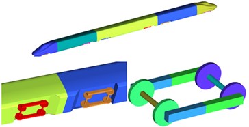
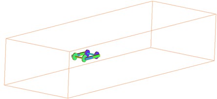
To study the impact of simplified bogies on the aerodynamic noise of the high-speed train, this paper established two models with including 6 complicated and simplified bogies respectively, as shown in Fig. 1 and Fig. 2. External windshield structures were used at train connections.
Fig. 1Train model with complicated bogies
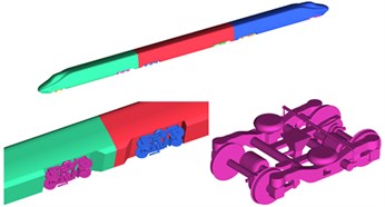
Fig. 2Train model with simplified bogies
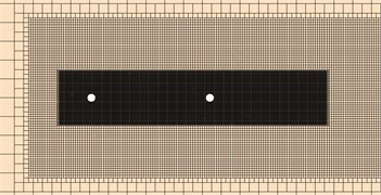
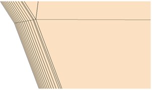
According to the geometric models, a computational domain for the aerodynamic noise of the high-speed train was established, as shown in Fig. 3. Grid distribution in the bogie area was shown in Fig. 4. Right ahead of head train was the inlet of velocity which was 300 km/h. Right behind the tail train was the outlet of pressure which was one standard atmospheric pressure. The bottom of train body was set as a slip ground boundary condition. Slip velocity was the same with the condition of velocity inlet. Train surface was set as fixed boundary. Other surfaces were set as symmetrical boundary conditions. The maximum grid size of train surface was set as 80 mm, and finally there are 67,520,000 elements.
According to the test standard ISO3095-2005 [23] for aerodynamic noise of the high-speed trains, 77 noise observation points were evenly arranged along the longitudinal direction of the train in the positions which were 3.5 m high from the track and 25 m away from the center line of track.
Fig. 3Computational domain for the aerodynamic noise of the high-speed train
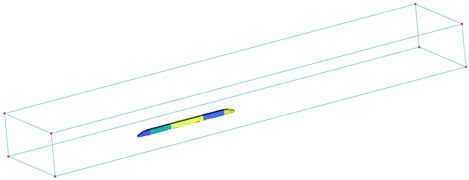
Fig. 4Grid distribution in the bogie area
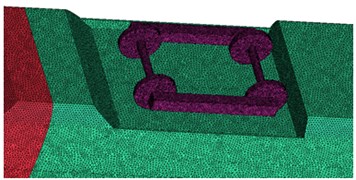
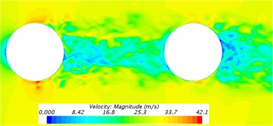
Fig. 5 displayed the comparison of far-field aerodynamic noises of train models with including simplified and complicated bogies in this paper. It could be seen from the analysis of Fig. 5 that sound pressure levels of various observation points differed little along the longitudinal direction and the difference of the maximum sound pressure level between complicated bogies and simplified bogies was only 0.3 dB. Therefore, complicated and simplified bogies had almost the same impact effect on the aerodynamic noises of the high-speed train. In addition, the complicated bogie model would improve modeling difficulty and computational time. At present, a number of published papers have only studied the aerodynamic characteristics and noises of simplified bogies too. Zhao [24] established a prediction model for noise in the area of a simplified bogie based on the software Ray noise and predicted the noises of various field points inside and outside the bogie area. Li [25] built three kinds of models including a simplified bogie, simplified train body without a bogie and train body of head train with a simplified bogie, and analyzed the flow field around the simplified bogie and the characteristics of aerodynamic sound field when the train ran at the speed of 200 km/h and 300 km/h. Gao [26] conducted a wind tunnel test on the aerodynamic noise of train including simplified bogies and analyzed the main noise characteristics of model and the contribution of the whole model. Zhu [8] only conducted numerical computation for the aerodynamic noise of bogie wheel sets and experimentally verified the correctness of numerically computational results. Based on the above analysis, it showed that it was also feasible to use a simplified bogie model to compute aerodynamic noises.
Fig. 5Comparison of aerodynamic noises of simplified and complicated bogies
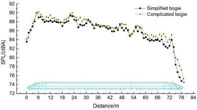
Fig. 6Comparison of aerodynamic noises of train with and without bogies
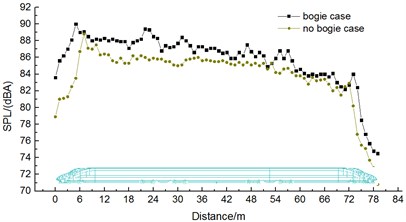
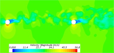
Fig. 6 displayed the distribution of aerodynamic noises of the high-speed train with and without bogies around the train body in order to analyze the impact of bogies on aerodynamic noise outside the train. As displayed from Fig. 6, the aerodynamic noises of the high-speed train had 6 local maximums in total along the longitudinal direction when 6 bogies were installed. 6 local maximums were respectively at the first bogie of head train, second bogie of head train, first bogie of mid train, second bogie of mid train, second bogie of tail train and first bogie of tail train. For the high-speed train without bogies, its far-field aerodynamic noise reached two local maximum sound pressure levels which were at the first bogie of head train and tail train. In addition, the far-field maximum sound pressure level of the high-speed train with bogies was 1.3 dBA greater than that of the high-speed train without bogies. Therefore, bogies are the main aerodynamic noise sources of high-speed trains. Studying the aerodynamic behavior and aerodynamic noise characteristics of bogies in detail has an important engineering value to reduce the aerodynamic noise of high-speed trains. As a result, this paper mainly studied the aerodynamic noise characteristics of a simplified bogie.
4. Computational model of a simplified bogie
4.1. Geometric model
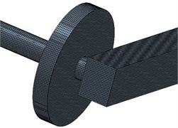
To study the flow behavior and aerodynamic noise characteristics of the bogie, a simplified bogie model was established, as shown in Fig. 7 (According to reference [10]). There were differences between the research results and actual results of the simplified bogie model. However, it was more conducive to theoretic research to find out the internal relationship between flow behavior and aerodynamic noises.
As the bogie of a real high-speed train contains braking device, suspension system, circuit system and so on, it will increase computational difficulty and be bad for studying the characteristics of aerodynamic noise regularity of the bogie if its small parts are modeled in detail. Therefore, this paper only established a simplified bogie system containing 2 axles and 2 wheel-sets and frames. Its size was shown in Fig. 7(a) and Fig. 7(b).
Fig. 7Three-dimensional geometric model
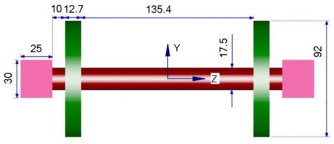
a) Lateral direction
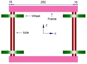
b) Vertical direction
4.2. Computational domain of aerodynamic characteristics
The computational domain of aerodynamic noises of the bogie was shown in Fig. 8. The length 344 cm of the bogie was taken as the benchmark. Therefore, the computational domain had its length 4, width and height 0.5. The center of the bogie was away from the entrance and 3 away from the exit. The center of the bogie was put in the central position of -axis. The cross-section right ahead of the bogie was inlet boundary which was set as the inlet condition of velocity. The velocity was 300 km/h in the case of computation. The cross-section right behind the bogie was outlet boundary which was set as the outlet condition of pressure and had one standard atmospheric pressure. The cross-sections right above, on the left and right of and below the bogie were set as symmetric boundary conditions.
Fig. 8Computational domain of the bogie
The surface of the bogie was set as fixed boundary which was no-slip wall boundary condition. Inlet, far field and outlet boundaries were set as off-field boundaries. Meanwhile, an absorption layer was set in these three positions in order to prevent the reflection of sound wave from polluting the internal flow field. In the case of reconstructing the pulsating quantity of turbulent flow, Fourier constant term was set as 200 in order to more accurately reconstruct sub-grid source items. Computational time step was set as 2e-5s; computational convergence step was set as 10.000; the duration of the computational and simulation physics was 0.2 s.
4.3. Mesh topology
This paper adopted STAR-CCM+ software to divide meshes in the surrounding areas of the bogie. The surface of the bogie was divided into quadrilateral elements and the space of the bogie was divided into hexahedral elements. To consider the influence of bogie surface on fluid flow, the boundary layer was divided at the surface of the bogie. To further reduce the turbulence effect in the tail region of the bogie, local refinement was conducted around the bogie, as shown in Fig. 9. To verify the influence of mesh accuracy on computational results, 6 sets of meshes with different sizes were divided to compute their aerodynamic noises respectively. The sound pressure level of the first set of meshes was 0.7 dBA greater than that of the second set of meshes and 0.5 dBA greater than that of the third set of meshes. In the meanwhile, the far-field sound pressure level of noise observation points changed little after local refinement was conducted for meshes (the fourth, fifth and sixth sets of meshes), which showed that the third set of meshes met the requirements of mesh independence. Therefore, this paper adopted the third set of meshes to carry out numerical simulation. The growth rate of the boundary layer was 1.1. The first boundary layer was 0.01 cm thick. The surface of various parts of the simplified bogie was 2 cm at most and 0.1 cm at least. The number of meshes in the computational domain of the bogie was 23.120.000.
Fig. 9Mesh topology of the bogie
a) Regional refined meshes
b) Meshes of boundary layers
c) Surface meshes
5. Aerodynamic flow field characteristics of the bogie
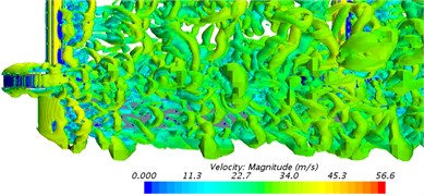
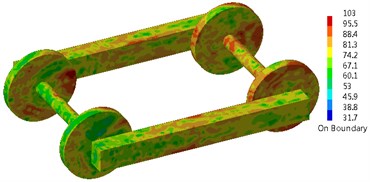
Fig. 10 presented cross-sections for the distribution of velocity contours around the bogie. As shown in Fig. 10(a), the cross-section of axles was circular. Therefore, the phenomenon of Karman Vortex Street was caused behind it. The turbulent flow phenomenon of a cylinder was obvious. From the above phenomena, it could be seen that the bogie would generate single-frequency noise when it was running at high speed and the frequency was related to the characteristic length of the cylinder. As shown in Fig. 10(b), the turbulent flow of the cylinder would not be caused at the rear of the wheel-set. It was mainly because the wheel-set was long and wide and the phenomenon of Karman Vortex Street would not be caused behind it. Through analyzing Fig. 10(c), it could be found that flow velocity was disordered in the area between axle and frame and the existence of vortexes in this area led to the un-stability of flow velocity. Thus, this connection position was the sound source position of main aerodynamic noises. From the velocity flow filed in the frame cross-section of Fig. 10(d), it showed that fluid velocity separated due to the choked flow effect of frame at the windward side in front of frame and velocity flow field was very disordered due to the further combination of fluid behind the leeward side.
Fig. 10Contours for the velocity distribution of the bogie
a) Cross-section of the axle
b) Cross-section of the wheel-set
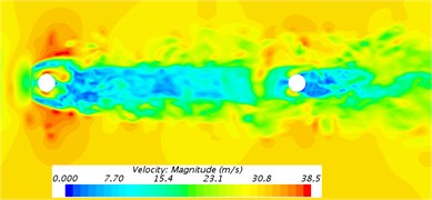
c) Cross-section between axle and frame
d) Cross-section of the frame
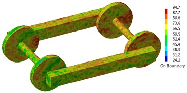
Fig. 11 showed the distribution of vorticity contour based on Q-criterion (The size was 10000/s2) when the bogie ran at the speed of 30 m/s. As shown in Fig. 11, axle and frame had great influence on airflow. Axle caused the turbulent flow of the cylinder while wheels could not cause the turbulent flow of the cylinder. Fluid in front of the front wheel-set had straight flow line and uniform flow velocity. The flow line bent when flowing through the axle of the front wheel-set. The flow line was layered. After bypassing the axle of the front wheel-set, the flow line interweaved and intertwined with each other, but it did not intersect. The flow line continued to flow to the rear wheel-set. To observe the flow structure of fluid flowing through front and rear wheel-sets more clearly, front and rear wheel-sets were studied simultaneously to make clear the vortex structure behind axles. Fig. 11(b), 11(c) and 11(d) showed the phenomenon of vortex shedding behind front and rear wheel-sets. The formation of vortexes behind axles could be generally divided into the following processes. Firstly, airflow reaching the axle of the front wheel-set had a high velocity. As the windward side of axles was an arc surface, airflow did not vertically flow to the surface of axles along the normal direction of the axle surface. As a matter of fact, there was a certain angle between the incident direction of airflow and axle surface. The flow phenomenon resulting from the incidence of airflow having a certain angle with solid surface was similar to the turbulent flow model formed by the oblique incidence of airflow to the plate. Due to the viscous effect of solid surface, a layer of fluid close to the solid surface had low flow velocity. Fluid far away from solid surface had high flow velocity. Then, the flow velocity of fluid increased with the increase of its distance between solid surface and flow velocity showed stratification phenomenon. On the other hand, fluid with high flow velocity and fluid with low flow velocity would interact with each other under the action of viscous stress inside fluid as fluid itself was viscous. Under this action, a very thin layer of fluid close to solid surface presented the trend of gradually getting close to solid surface in the process of flowing forward. Under the condition of high speed, the trend of getting close to the wall surface would finally develop into local backflow. A series of low-speed streaks would further appear in places close to solid surface. Low-speed streaks were the initial stage of vortex development. As low-speed vortexes continued to grow, the viscous effect of solid surface weakened the binding effect on solid surface. At this time, low-speed streaks would vibrate. Then, vortexes rolled up, shed, stretched forward along the flow direction and formed horseshoe vortexes or hairpin vortexes. On the whole, horseshoe vortexes or hairpin vortexes were the most common turbulent vortexes caused by the wheel-sets of the bogie. On the other hand, turbulent vortexes shedding from the front wheel-set were large in scale, whose energy was mainly included in the large-scale vortex body with relatively concentrated vorticity. These turbulent vortexes stretched along the flow direction and hit against the axle of the rear wheel-set. Vortex bodies broke and scattered into smaller-scale vortexes. The range of vortex distribution was expanded.
The area of interaction between turbulent vortexes and wheel-sets appeared at the top and bottom surface of axles. Vortex bodies generated and shed periodically at the axle of front and rear wheel-sets, which would lead to drastic fluctuations in pressure at the top and bottom surface of axles. Such fluctuations gave rise to drastic changes in the fluctuating pressure (Fluctuating pressure in the vertical direction was called as fluctuating lift) of axles in the vertical direction.
Fig. 11The distribution of vorticity contour surface
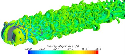
a) Direction of axial side
b) Vertical direction
c) Longitudinal direction close to wheel-sets
d) Longitudinal direction close to axles
6. Aerodynamic noise propagation characteristics of the bogie
Based on the above computational results of LES, FW-H acoustic model could be used to directly carry out numerical solution for the aerodynamic noise of the bogie in the computational software of aerodynamic characteristics. However, only the curve of noise distribution could be obtained and the contour of aerodynamic noise could not be computed to identify the aerodynamic noise sources of the bogie and observe the propagation characteristics of aerodynamic noises. Therefore, this paper again used BEM to compute the contours of aerodynamic noises of the bogie.
6.1. Arrangement of observation points of aerodynamic noises
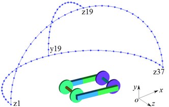
To study the distribution characteristics of the far-field aerodynamic noise of the bogie, the geometric center of the bogie was taken as the origin. The radius was 3.5 m. Observation points of 1/2 circle were arranged every 5° along the - plane and - plane and Observation points of 1/4 circle were arranged every 5° along the - plane. Fig. 12 showed the corresponding relationship between the arrangement of observation points of the aerodynamic noise of the bogie and the coordinate plane. This paper stipulated the - plane, - plane and - plane as the vertical plane, longitudinal plane and lateral plane respectively. Main noise observation points were called as , , and respectively.
Fig. 12Schematic diagram for the observation points of aerodynamic noises
6.2. Distribution characteristics of aerodynamic noises
Fig. 13 presented the A-weighting sound pressure level distribution of noise observation points in all planes. From an analysis on Fig. 13, it could be seen that:
(1) In the vertical plane, the aerodynamic noise of the bogie had obvious directivity. Perpendicular to the direction of incoming flow (the direction of 90°and 270°), the aerodynamic noise amplitude of the bogie was greater than that in the direction of incoming flow (0°) and wake flow (180°). Therefore, the main radiation directions of aerodynamic noises were 90° and 270° in the vertical plane. It was dipole aerodynamic noise.
(2) In the longitudinal plane, the aerodynamic noise of the bogie had obvious directivity. Perpendicular to the direction of incoming flow (the direction of 95° and 265°), the aerodynamic noise amplitude of the bogie was greater than that in the direction of incoming flow (0°) and wake flow (180°). Therefore, the main radiation directions of aerodynamic noises were 90° and 270° in the longitudinal plane.
(3) In the lateral plane, the aerodynamic noise of the bogie had obvious directivity. Perpendicular to the direction of incoming flow (the direction of 90° and 270°), the aerodynamic noise amplitude of the bogie was greater than that in the direction of incoming flow (0°) and wake flow (180°). Therefore, the main radiation directions of aerodynamic noises were 90° and 270° in the lateral plane.
(4) In the vertical plane, longitudinal plane and lateral plane, maximum sound pressure levels were 53.4 dBA, 57.3 dBA and 56.2 dBA. It thus could be seen that the maximum sound pressure level was at the observation point in the direction of 95° in the longitudinal plane and had the directivity of dipole aerodynamic noise.
Fig. 13Distribution of far-field aerodynamic noises of the bogie
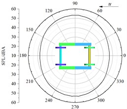
a) Vertical plane
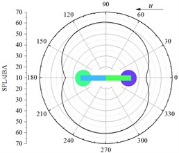
b) Longitudinal plane
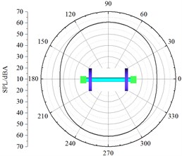
c) Lateral plane
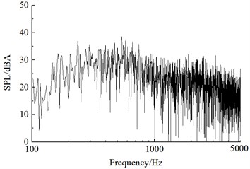
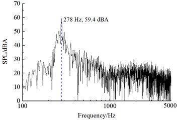
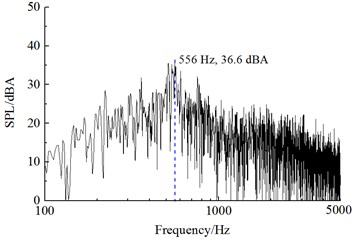
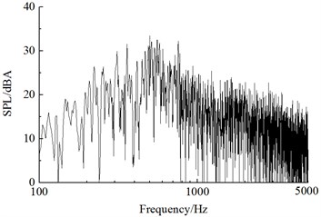
Fig. 14 displayed a comparison of linear frequency spectrums of aerodynamic noises at various observation points including , , and . As shown in the figure, the main energy of aerodynamic noises focused on the frequency range of 200 Hz-1000 Hz, and it was a broadband noise. The radiation direction of main single-frequency noise was in the direction of 90° of incoming flow rather than 0° of incoming flow and 180° of wake flow. It was mainly because the phenomenon of Karman Vortex Street of cylindrical bars resulted in the drastic fluctuating lift of bogie parts. Its main single-frequency noise was 278 Hz and it was mainly caused by fluctuating lift. The single-frequency noise 556 Hz was mainly caused by the fluctuating drag of the bogie. Thus, it could be seen that the main single frequency of fluctuating drag was twice that of fluctuating lift.
Fig. 14Frequency spectrums of sound pressure level of the bogie
a) Point
b) Point
c) Point
d) Point
6.3. Setting of acoustics meshes
Acoustic BEM was applied to identify the aerodynamic noise sources of the bogie and study the propagation characteristics of aerodynamic noises. The time-domain signals of surface fluctuating pressure of the bogie were extracted from the flow field and BEM was adopted to solve the sound pressure on the sound field node of observation points. Acoustic software Virtual. Lab was used to compute the sound propagation of bogies. Sound pressure boundary conditions were used to map the surface fluctuating pressure of the bogie obtained by CFD computation to the acoustic meshes of the bogie. Discrete Fourier transform (DFT) was adopted to transfer the data of surface fluctuating pressure. In the meanwhile, the computation of acoustic response and an analysis on acoustic far-field response could obtain the aerodynamic noise sources and far-field aerodynamic noise radiation of the bogie. Fig. 15 showed the acoustic meshes of the bogie and Fig. 16 presented the meshes of observation points in a sphere with a radius of 1 m. The maximum acoustic mesh size at the surface of the bogie should satisfy the requirements of maximum frequency:
wherein, was the largest acoustic mesh size; represented computed maximum frequency, 5000 Hz; referred to the propagation velocity of sound in the air, 340 m/s.
From Eq. (3), the largest size of acoustic meshes was 11 cm through computation. In the computation of sound propagation, this paper set the maximum mesh size as 2 cm. It could be found that the acoustic meshes computed in this paper satisfied the requirement of sound propagation for minimum wavelength.
Fig. 15Acoustic meshes of the bogie
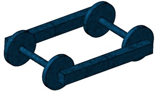
Fig. 16Observation points in the far-field sound field of the bogie
6.4. Aerodynamic noise sources of the bogie
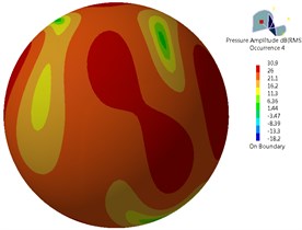
Fig. 17 showed contours for the sound pressure level distribution of aerodynamic noises of bogie surface at 278 Hz, 556 Hz, 834 Hz and 1112 Hz. Through conducting an analysis on Fig. 17, it could be seen that the main energy of the bogie focused on mid-low frequencies. Main aerodynamic noise sources were from the axle at the second end of the train and the position of wheel-set surface close to one side of axles. Frames were not main aerodynamic noise sources. The energy of sound pressure level at the surface of axle at the first end of the train was stronger than that in the axle at the second end of the train. After flowing through the axle at the second end of the train, airflow furthered intensified its turbulence through turbulent flow in the axle at the second end of the train. Then, airflow had an influence on the axle at the first end of the train and intensified the surface fluctuating pressure at the first end of the train, which thus caused that the axle at the first end of the train was main aerodynamic noise source. Meanwhile, airflow became more disordered in this position due to the interaction between axle and wheel-set. Fluctuating pressure was large. It was also main aerodynamic noise source. Thus, areas in which vortexes were intensively distributed and positions where airflow was separated easily were the main aerodynamic noise sources of the simplified bogie.
Fig. 17Far-field aerodynamic noise sources of the bogie
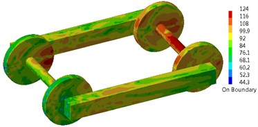
a) 278 Hz
b) 556 Hz
c) 834 Hz
d) 1112 Hz
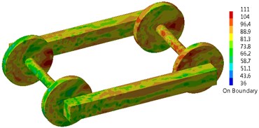
6.5. Aerodynamic noise radiation in the far field
Fig. 18 presented contours for the sound pressure level radiation of far-field aerodynamic noises of bogie surface at 278 Hz, 556 Hz, 834 Hz and 1112 Hz. As shown in Fig. 18, the main radiation direction of far-field aerodynamic noises of the bogie was right above and below the bogie rather than the left and right side of the bogie. Therefore, the aerodynamic noise of the bogie had the characteristics of dipole aerodynamic noises. In the main single frequencies including 278 Hz, 556 Hz, 834 Hz and 1112 Hz, maximum sound pressure levels were 62.2 dB, 43.6 dB, 32.7 dB and 30.9 dB. Thus, it could be seen that the main energy of the bogie focused on mid-low frequencies.
Fig. 18Aerodynamic noise radiation of the bogie in the far field
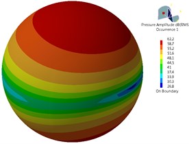
a) 278 Hz
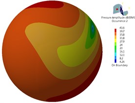
b) 556 Hz
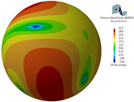
c) 834 Hz
d) 1112 Hz
7. Conclusions
This paper studied the aerodynamic flow behavior and aerodynamic noise of the bogie and obtained the following conclusions:
1) Bogies made the noise of the high-speed train obviously serious, the noise near the bogie increased obviously, and the maximum sound pressure level increased by 1.3 dBA. Therefore, bogies were the main aerodynamic noise source of the high-speed train.
2) The turbulence effect of bogie axles and wheel-sets on airflow led to the generation and shedding of abundant vortexes in the bogie area. Vortexes of periodic generation and shedding would cause large fluctuating pressure at the top and bottom surface of axles and wheel-sets.
3) The noise power at the surface of the bogie was mainly distributed in axles and at the surface of the wheel-set close to the one side of axles, which was mainly caused by fluctuating lift and then resulted from the windward side of wheels.
4) The far-field aerodynamic noise of the bogie had the directivity of dipole noise in various planes (vertical plane, longitudinal plane and lateral plane). In the vertical plane and lateral plane, the main radiation directions of aerodynamic noises were 90° and 270°. In the longitudinal plane, the radiation directions of the maximum sound pressure level were 95° and 265°. In the vertical plane, longitudinal plane and lateral plane, maximum sound pressure levels were 53.4 dBA, 57.3 dBA and 56.2 dBA. Thus, it could be seen that the maximum sound pressure level was in the direction of 95° in the longitudinal plane.
5) The far-field aerodynamic noise of the bogie was broadband noise, whose main energy focused on the frequency range of 200 Hz to 1000 Hz. The main radiation direction of far-field aerodynamic noise was right above and below the bogie rather than the left and right side of the bogie. It was typical dipole aerodynamic noises.
6) The main single frequency of the bogie was 278 Hz, which was mainly caused by fluctuating lift. The single-frequency noise 556 Hz mainly resulted from the fluctuating drag of the bogie. The main single frequency of fluctuating drag was twice that of fluctuating lift.
References
-
Shen Z. Y. Dynamic environment of high-speed train and its distinguished technology. Journal of the China Railway Society, Vol. 28, Issue 4, 2006, p. 1-5.
-
Nagakura K. Localization of aerodynamic noise sources of Shinkansen train. Journal of Sound and Vibration, Vol. 293, Issue 3, 2006, p. 547-556.
-
Wang B. M. EMU Overall and Bogie. Southwest Jiaotong University Press, Chengdu, 2014.
-
Kitagawa T., Nagakura K. Aerodynamic noise generated by shinkansen cars. Journal of Sound and Vibration, Vol. 231, Issue 5, 2000, p. 913-924.
-
Zhang W. H. Study on top-level design specifications of high-speed train. Journal of the China Railway Society, Vol. 34, Issue 9, 2012, p. 15-19.
-
Mellet C., Letourneaux F., Poisson F., et al. High speed train noise emission: latest investigation of the aerodynamic/rolling noise contribution. Journal of Sound and Vibration, Vol. 293, Issue 3, 2006, p. 535-546.
-
Nagakura K. Localization of aerodynamic noise sources of Shinkansen train. Journal of Sound and Vibration, Vol. 293, Issue 3, 2006, p. 547-556.
-
Zhu J. Y., Hu Z. W., Thompson D. J. Flow simulation and aerodynamic noise prediction for a high-speed train wheelset. International Journal of Aeroacoustics, Vol. 13, Issues 7-8, 2014, p. 533-552.
-
Thompson D. J., Latorre I. E., Liu X., et al. Recent developments in the prediction and control of aerodynamic noise from high-speed trains. International Journal of Rail Transportation, Vol. 3, Issue 3, 2015, p. 119-150.
-
Zhu J. Y., Hu Z. W., Thompson D. J. Analysis of aerodynamic and aeroacoustic behaviour of a simplified high-speed train bogie. Noise and Vibration Mitigation for Rail Transportation Systems, 2015, p. 489-496.
-
Batham J. P. Pressure distributions on circular cylinders at critical Reynolds numbers. Journal of Fluid Mechanics, Vol. 57, Issue 2, 1973, p. 209-228.
-
Jacob M. C., Boudet J., Casalino D., et al. A rod-airfoil experiment as a benchmark for broadband noise modeling. Theoretical and Computational Fluid Dynamics, Vol. 19, Issue 3, 2005, p. 171-196.
-
Iglesias E. L., Thompson D. J., Smith M. G. Experimental study of the aerodynamic noise radiated by cylinders with different cross-sections and yaw angles. Journal of Sound and Vibration, Vol. 361, Issue 5, 2016, p. 108-129.
-
Wakabayashi Y., Kurita T., Yamada H., et al. Noise measurement results of Shinkansen high-speed test train (FASTECH360S,Z). Noise and Vibration Mitigation for Rail Transportation Systems, 2008, p. 63-70.
-
Kurita T., Wakarayashi Y., Yamada H., et al. Reduction of wayside noise from Shinkansen high-speed trains. Journal of Mechanical Systems for Transportation and Logistics, Vol. 4, Issue 1, 2011, p. 1-12.
-
Zheng X. H., Zhang J. Y., Zhang W. H. Numerical simulation of aerodynamic drag for high-speed train bogie. Journal of Traffic and Transportation Engineering, Vol. 11, Issue 2, 2011, p. 45-51.
-
Yang Z. G., Gao Z., Cheng Y., et al. Numerical analysis on influence on aerodynamic performance of high- speed train caused by installation of skirt plates. Computer Aided Engineering, Vol. 19, Issue 3, 2010, p. 16-21.
-
Xi Y. H., Mao J., Gao L., et al. Aerodynamic force/moment for high-speed train bogie in crosswind field. Journal of Central South University (Science and Technology), Vol. 45, Issue 5, 2014, p. 1705-1714.
-
Zhang Y. D., Zhang J. Y., Li T., et al. Numerical research on aerodynamic noise of trailer bogie. Journal of Mechanical Engineering, Vol. 52, Issue 16, 2016, p. 106-116.
-
Huang S., Yang M. Z., Li Z. W., et al. Aerodynamic noise numerical simulation and noise reduction of high-speed train bogie section. Journal of Central South University (Science and Technology), Vol. 42, Issue 12, 2011, p. 3899-3904.
-
Lighthill M. J. On sound generated aerodynamically. Part 1: General theory. Proceedings of the Royal Society of London, Series A, Mathematical and Physical Sciences, Vol. 211, Issue 1107, 1952, p. 564-587.
-
Williams J. E. F., Hawkings D. L. Sound generation by turbulence and surfaces in arbitrary motion. Philosophical Transactions for the Royal Society of London, Series A, Mathematical and Physical Sciences, Vol. 264, Issue 1151, 1969, p. 321-342.
-
Railway Application-Acoustics Measurement of Noise Emitted by Railbound Vehicle. EN ISO 3095, 2005.
-
Zhao Y., Wen Z. F., Xiao X. B., Zhou X., Jin X. S. Influence of wheel structure on the noise in bogie area. Noise and Vibration Control, Vol. 34, Issue 4, 2014, p. 24-29.
-
Li H., Xiao X. B., Jin X. S. Investigation into aerodynamic noise characteristics of train head car bogie based on simplified models. Journal of Mechanical Engineering, Vol. 52, Issue 8, 2016, p. 152-161.
-
Gao Y., Wang Y. G., Wang J. T., Shen Z., Yang Z. G. Testing study of aerodynamic noise for high speed train model in aero-acoustic wind tunnel. Technical Acoustics, Vol. 32, Issue 6, 2013, p. 506-510.
Cited by
About this article

