Abstract
The ultrasonic motor is an uncertain time-varying nonlinear system because of the nonlinearity of the piezoelectric material, the friction and the temperature. For example, the operating time of the mechanical switch actuated by the ultrasonic motor in regular stroke is highly dispersed. Unfortunately, it is difficult to establish accurate mathematical model. In this paper, an analytical autoregressive process model (AR) is employed to identify and control the ultrasonic motor. First of all, dispersed operating time of the mechanical switch actuated by the ultrasonic motor is investigated. Then, the AR model is established to predict the operating time of the ultrasonic motor on the basis of the statistical data to reduce the nonlinear behavior of the ultrasonic motor, and to improve the accuracy and obtain a good time response of the switch. The simulation results are agreed with experimental results, confirming the effectiveness of proposed model. Furthermore, we adopt the predicted result of the AR model to control the mechanical switch actuated by the ultrasonic motor. The analytical investigation is fulfilled with two target operating time ranges, namely 12 ms and 24 ms. Comparison of the results obtained from the AR model and the experimentation reveal that the standard deviations are less than 95.3 μs and 102.7 μs with maximum errors equal to 0.41 % and 0.44 % respectively. Thereby, the proposed dispersed operating time control is performed. Findings indicate that the maximum errors for the operating time of the mechanical switch are less than 140 μs and 110 μs with ±0.85 % and ±0.42 % respectively.
1. Introduction
During the last few decades, piezoelectric actuators and ultrasonic motors have been widely employed in many fields including micro-positioning [1], semiconductor manufacturing [2] and biomedical applications [3]. Particularly, ultrasonic motors are widely used for variable apertures [4], optical cross-connect switches [5] and circuit breakers [6]. Major advantages of the ultrasonic motor are mainly high accuracy, self-locking force, instantaneous response time and high switching speed [7]. However, the ultrasonic motor is an uncertain time-varying nonlinear system because of the nonlinearity of the piezoelectric material, the friction between a stator and a mover of the ultrasonic motor, and the temperature [8, 9]. For example, the operating time of the mechanical switch actuated by the ultrasonic motor in regular stroke is highly dispersed. However, the consistency of the operating time is a key target for the mechanical switch. Therefore, it is necessary to propose a method of overcoming the dispersed operating time of the mechanical switch to improve accuracy and performance of the system.
There are generally three models of the ultrasonic motor, namely the accurate model, the simplified model, and the model free. Hagood [10] and Tsai [11] built a typical dynamic model of the traveling wave rotary ultrasonic motor and the bimodal linear ultrasonic motor. Maas [12] also proposed a complete control scheme for the traveling wave rotary ultrasonic motor with an inverse model structure for the cascaded control based on the analytical model. Giraud [13] presented a causal modeling and identification. Control models based on the accurate method can be employed to describe the operating principle of the ultrasonic motor and predict its linear performance. However, the ultrasonic motor is a complex nonlinear system. Therefore, it is extremely complicated to control such a system through the accurate method under different external operating conditions. T. Senjyu [14] proposed a simplified mathematical model. T. Senjyu [14] also designed a controller based on the adaptive control algorithms. Furthermore, T. Senjyu [15] proposed a second-order system, involving the non-linearity of the system and approximation of the dead-zone of the control input. Other scholars [16, 17] also proposed some control methods based on the simple models. The simplified model is limited to identify parameters of the system such as stability and dynamic performance of the motor. Therefore, it is difficult to find out a simple and efficient mathematical model for the ultrasonic motor. In order to solve this problem, the free mathematical modeling was proposed. Lin [18] proposed a fuzzy adaptive model-following position control for the traveling wave rotary ultrasonic motor. Moreover, Lin designed a recurrent fuzzy neural network controller for the ultrasonic motor driven system [19], and a wavelet neural network controller via the adaptive sliding-mode technique for the linear ultrasonic motor [20]. In recent years, extensive studies [21, 22] have been carried out on the advanced control strategies and they are ending up with fruitful achievements. However, as for the implementation of these methods, computational cost and high complexity are badly required to be addressed.
Based on the investigations and models analyzed above, we can conclude that it is difficult to overcome the dispersed operating time of the switching action with the accurate model for its limitations like the non-linear behavior. In addition, the simplified model has the problem of inaccuracy for that the relationship between its input and output is not clear. Therefore, this problem could be solved by an autoregressive model (AR model). This model consists of data collection and time points which are generally sampled in equal time intervals [23]. Time series prediction refers to the process by which future values of the system could be properly predicted. Such prediction is based on the data information obtained during the system operation, so it has an advantage of the dispersed operating time control of the mechanical switch actuated by the ultrasonic motor.
In this study, the dispersed operating time control of the mechanical switch actuated by the ultrasonic motor is presented. The paper consists of six sections. In section 1, a short introduction to the research topic is provided together with a preliminary idea as well as the novelty of our research. In Section 2, the structure of V-shape ultrasonic motor is introduced. In Section 3, a drive and control system is built and the dispersed operating time of the mechanical switch actuated by the ultrasonic motor is investigated. In Section 4, some nonlinear phenomena of ultrasonic motor are studied. In Section 5, an AR model is proposed to predict the operating time. In Section 6, an experimental investigation of the system control using the AR model was performed. Findings reveal that the operating time of the mechanical switch is less than 140 μs and 110 μs with only ±0.85 % and ±0.42 % respectively.
2. Structure of V-shape ultrasonic motor
The V-shape ultrasonic motor [24] is selected to drive the mechanical switch. The V-shape ultrasonic motor is comprised of a V-shape stator, a mover, a clamp, and a base as shown in Fig. 1. The V-shape stator consists of two transducers connected with a certain angle. A stator of the V-shape ultrasonic transducer is formed by two mutually perpendicular continuous variable section Langevin transducers, utilizing the inverse piezoelectric effect of piezoelectric ceramic to achieve conversion of electrical energy to mechanical energy and through friction drive to realize motion transfer. The V-shaped motor is operated in the coupled the symmetrical and asymmetrical modes, as shown in Fig. 2. The elliptical motion is generated by applying a corresponding voltage excitation at the driving foot of the V-shape ultrasonic motor. The phase difference between the voltage excitation of the two transducers is 90°. Furthermore, the rotor moves in response to the elliptical motion of the driving foot due to the friction effect.
Fig. 1Structure of V-shape ultrasonic motor
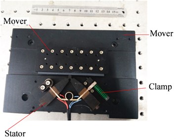
Fig. 2Symmetrical and asymmetrical modes: a) asymmetrical mode, b) symmetrical mode
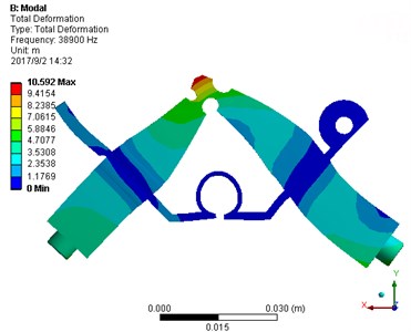
a) Asymmetrical mode
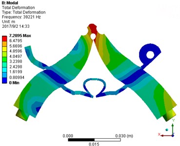
b) Symmetrical mode
3. Dispersed operating time of the mechanical switch actuated by the ultrasonic motor
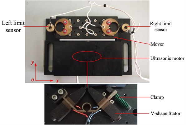
In electrical and optical applications, the mover needs to be reciprocated in a certain range (5 mm), as shown in Fig. 3. In view of the high speed and fast response of the ultrasonic motor (on/off time in a millisecond), the mechanical switch actuated by the ultrasonic motor is proposed. The operating time of the switch action is , during which the motor goes through range travel , and the switch times is .
The driving and controlling system of the mechanical switch actuated by the ultrasonic motor is developed, as shown in Fig. 4. The system includes a control and data acquisition system (National Instruments PXI-6229 with LabVIEW, Austin, TX, USA), an ultrasonic motor driving circuit, a non-contact laser displacement sensor (LK-H150, Keyence Corp., Osaka, Japan), and an ultrasonic motor with the limit sensors. The ultrasonic motor as an actuator carries out the switch motion in the sensor range, as shown in Fig. 5.
Fig. 3Construction of the mechanical switch actuated by the ultrasonic motor
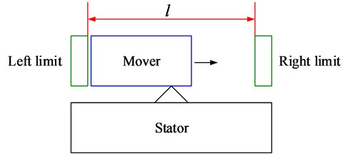
Fig. 4Diving and controlling system of the mechanical switch actuated by the ultrasonic motor
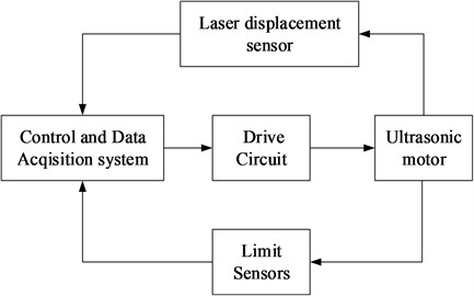
Fig. 5Mechanical switch actuated by the ultrasonic motor
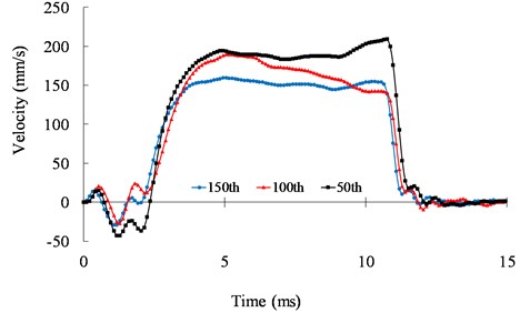
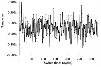
The relationship between the operating time of the switch action and the switch times is shown in Fig. 6. The ultrasonic motor is operated within the range of the two limit sensors under an open-loop condition. It can be seen from Fig. 6 that the operating time of the switch action is highly dispersed. The dispersion of the operating time is derived from the nonlinearity of piezoelectric materials, the uncertainty of the friction, and the temperature of the motor. Fig. 7 shows the speed responses of the 50th, 100th, and 150th cycles. From Fig. 7, we can see the operating time of the mechanical switch actuated by the ultrasonic motor varies at different cycles.
Fig. 6Relationship between the operating time of the mechanical switch actuated by the ultrasonic motor under 39.6 kHz and 500 Vpp
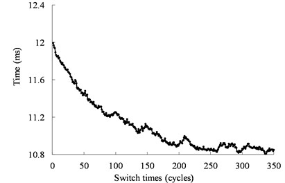
Fig. 7Speed response of the mechanical switch actuated by the ultrasonic motor under 39.6 kHz and 500 Vpp at the 50th, 100th, and 150th cycles
4. Open-loop characteristics of the ultrasonic motor
The open-loop motion characteristics of the motor are studied in this section. The ultrasonic motor is usually used to adjust the excitation frequency for the speed control as well as the phase difference for the direction control. Fig. 8 shows the speed response of the motor under different excitation frequencies. The excitation frequency has a significant effect on the speed of the ultrasonic motor. According to the system identification method, the second order system of the ultrasonic motor is identified to be based on the input excitation and the output displacement. The transfer function of the second order system can be expressed as:
is the magnification factor; is the damping ratio; is the natural frequency; . Identification parameters are listed in Table 1. The frequency of the excitation signals varies with the second-order system parameters. Therefore, it is difficult to control the ultrasonic motor as a second-order system.
Table 1Identification result
Frequency (kHz) | |||
41.5 | 321.5 | 25.44 | 558.1 |
41 | 324 | 25.33 | 578.7 |
40.5 | 295 | 24.02 | 587.5 |
40 | 296.7 | 23.74 | 642.9 |
39.5 | 298 | 23.35 | 647.4 |
Fig. 8Speed response of the motor in different excitation conditions under 500 Vpp
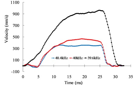
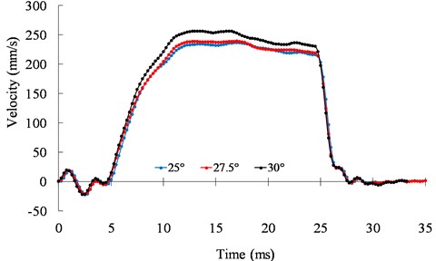
Fig. 9 shows the speed responses of the motor at different temperatures. The result shows the speed characteristics of the motor varies at different temperatures. The ultrasonic motor shows a strong nonlinearity and uncertainty.
Fig. 9Speed responses of the motor under 25°, 27.5°, and 30°
5. Modeling
In this paper, the AR model is used to predict the operating time of the mechanical switch actuated by the ultrasonic motor using the real-time recursive estimation of the limited memory [23].
(1) Measure the operating time of the mechanical switch actuated by the ultrasonic motor, , , , …, .
(2) Set:
where , , …, are unknown variables. The th operating time is linearly related to the operating time , , , …, ().
Therefore, according to the observed data , , …, , we can obtain the equation group in the form of matrix as follows:
Written as the following equation:
(3) We can obtain the minimum square estimation from Eq. (4), as follows:
where is the transposed matrix .
Hence, the estimation is given by:
(4) The delay time of the motor start time is:
target operating time. The start time of the motor can be determined from Eq. (7).
(5) Repeat Steps (1)-(4).
Akaike Information Criterion (AIC) is used to determine the order of AR model [31]. The order might be set as , described as:
where is the variance of the residual error between the real operating time and the objective time . The residual is expressed as:
In this paper, we collect the operating time of the mechanical switch actuated by the ultrasonic motor. The AIC results are given in Table 2. When 1, AIC () is the minimum, thus we adopt the AR(1) model.
Table 2Test of AIC rule
1 | 2 | 3 | … | |
AIC (m) | 3574.2 | 3590.1 | 3660.5 | … |
6. Model solution and experimental validation
In this section, the AR model is used to control the operating time of the mechanical switch actuated by the ultrasonic motor. The schematic of the control algorithm is shown in Fig. 10.
Fig. 10Schematic of control algorithm
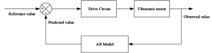
Fig. 11Comparison between the predictive results and the experimental results
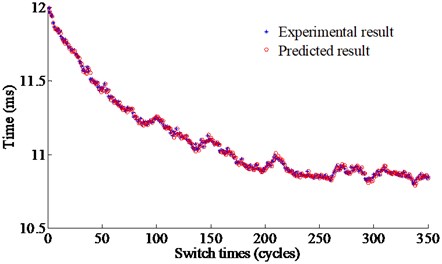
a) Under 40 kHz, and 500 Vpp
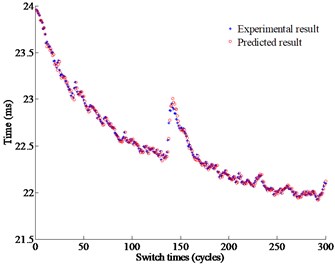
b) Under 40.5 kHz, and 500 Vpp
Fig. 11 shows the comparison between the predictive and experimental results under different operating conditions. The target operating time is set at 12 ms and 24m s respectively under the different operating conditions. From Fig. 11, the predictive values are very close to the experimental values where the maximum deviation are respectively 0.0953 ms, and 0.1027 ms with the maximum errors 0.42 % and 0.44 % respectively.
Fig. 12 shows the real operating time of the mechanical switch actuated by the ultrasonic motor under 40 kHz and 500 Vpp. The time is less than 0.14 ms with the error less than ±0.85 %. Fig. 13 shows the real operating time of the mechanical switch actuated by the ultrasonic motor under 40.5 kHz and 500 Vpp. The time is less than 0.11 ms with the error less than ±0.42 %. The distribution of the working time is shown in Fig. 14. The statistical results show that the velocity is normally distributed.
Fig. 12Operating time of the mechanical switch actuated by the ultrasonic motor from the experimental results under 40 kHz, and 500 Vpp
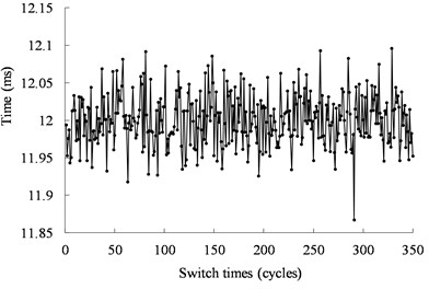
a) Real operating time
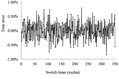
b) Error between the operating time and the target time
Fig. 13Operating time of the mechanical switch actuated by the ultrasonic motor from the experimental results under 40 kHz and 500 Vpp
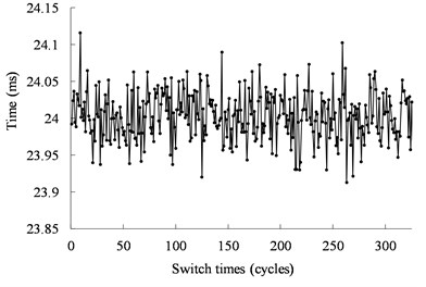
a) Real operating time
b) Errors between the operating time and the target time
Fig. 14Statistical distribution of the operating time of the mechanical switch actuated by the ultrasonic motor from the experimental results
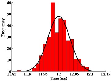
a) Under 40 kHz and 500 Vpp
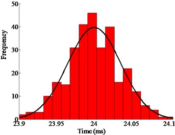
b) Under under 40.5 kHz and 500 Vpp
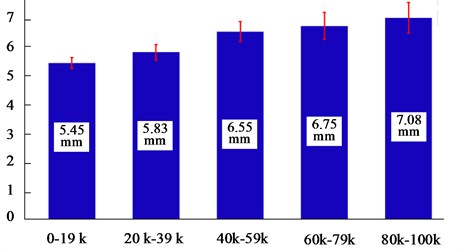
The experiment on the motor reliability was carried out. The motor was turned on (Fixed operating time: 10.5 ms) and off (Fixed operating time: 10.5 ms), as shown in Fig. 15. From Fig. 16, we can see that among the 100,000 cycles, each cycle is greater than 5 mm in displacement. It ensures that the motor has enough time to delay the start. The motor can be reliably turned on and off in the 100,000 cycles. In this way, reliability of the motor is verified.
Fig. 15Test of the motor reliability
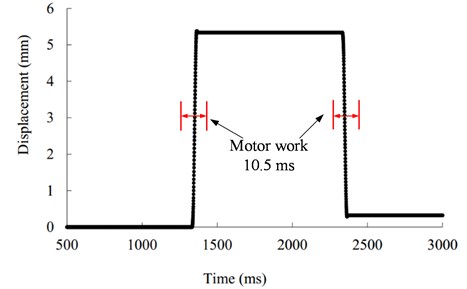
Fig. 16Experimental results of the motor reliability
7. Conclusions
In this work, the dispersed operating time of the switch actuated by the ultrasonic motor is presented. The control method based on the AR model has been proposed to overcome the nonlinearity and the uncertainty of the ultrasonic motor. The target of the control is to make the operating time of the mechanical switch actuated by the ultrasonic motor consistent. Firstly, a driving and controlling system is built. The dispersed operating time of the switch is presented. In addition, the nonlinear phenomena of the ultrasonic motor are investigated. Then an AR model is proposed to predict the operating time based on the statistical data. The analytical investigation was fulfilled with two target operating time ranges which were set to 12 ms and 24 ms. Comparison of the results obtained from the AR model and the experimental results revealed that the standard deviations are less than 95.3 μs and 102.7 μs with the maximum errors equal to 0.41 % and 0.44 % respectively. Thereby, the proposed dispersed operating time control was performed. Findings indicated that the maximum errors of the operating time of the mechanical switch are less than 140 μs and 110 μs, and with ±0.85 % and ±0.42 % respectively.
References
-
Bansevičius R., Bubulis A., Grybas I., Jūrėnas V., Kulvietis G. Development of two modifications of piezoelectric high resolution rotary table. Journal of Vibroengineering, Vol. 15, 2013, p. 2124-2129.
-
Wang L., Wielert T., Twiefel J., Jin J., Wallaschek J. A rod type linear ultrasonic motor utilizing longitudinal traveling waves: proof of concept. Smart Materials and Structures, Vol. 26, Issue 8, 2017, p. 85013.
-
Mo J., Qiu Z., Wei J., Zhang X. Adaptive positioning control of an ultrasonic linear motor system. Robotics and Computer-Integrated Manufacturing, Vol. 44, 2017, p. 156-173.
-
Li X., Zhou S. A novel piezoelectric actuator with a screw-coupled stator and rotor for driving an aperture. Smart Materials and Structures, Vol. 25, 2016, p. 35027.
-
Oohira F., Iwase M., Matsui T., Hosogi M., Ishimaru I., Hashiguchi G., Mihara Y., Iino A. Self-hold and precisely controllable optical cross-connect switches using ultrasonic micro motors. Journal of Selected Topics in Quantum Electronics, Vol. 10, 2004, p. 551-557.
-
Graber L., Smith S., Soto D., Nowak I., Owens J., Steurer M. A new class of high speed disconnect switch based on piezoelectric actuators. Electric Ship Technologies Symposium, 2015, p. 312-317.
-
Zhao C. Ultrasonic Motors: Technologies and Applications. Springer Science and Business Media, 2011.
-
Gao J., Cao S. Q. Second-order approximation of primary resonance of a disk-type piezoelectric stator for traveling wave vibration. Nonlinear Dynamics, Vol. 61, 2010, p. 591-603.
-
Shi J., Zhao F., Shen X., Wang X. Chaotic operation and chaos control of travelling wave ultrasonic motor. Ultrasonics, Vol. 53, 2013, p. 1112-1123.
-
Hagood N. W., Mcfarland A. J. Modeling of a piezoelectric rotary ultrasonic motor. Transactions on Ultrasonics, Ferroelectrics, and Frequency Control, Vol. 42, 1995, p. 210-224.
-
Tsai M., Lee C., Hwang S. Dynamic modeling and analysis of a bimodal ultrasonic motor. Transactions on Ultrasonics, Ferroelectrics, and Frequency Control, Vol. 50, 2003, p. 245-256.
-
Maas J., Schulte T., Frohleke N. Model-based control for ultrasonic motors. Transactions on Mechatronics, Vol. 5, 2000, p. 165-180.
-
Giraud F., Semail B., Audren J. Analysis and phase control of a piezoelectric traveling-wave ultrasonic motor for haptic stick application. Transactions on Industry Applications, Vol. 40, 2004, p. 1541-1549.
-
Senjyu T., Yokada S., Miyazato H., Uezato K. Speed control of ultrasonic motors by adaptive control with a simplified mathematical model. Proceedings – Electric Power Applications, Vol. 145, 1998, p. 180-184.
-
Senjyu T., Nakamura M., Urasaki N., Sekine H., Funabashi T. Mathematical model of ultrasonic motors for speed control. Electric Power Components and Systems, Vol. 36, Issue 6, 2008, p. 637-648.
-
Shi J., Bo L., Yu Z. Study on self-tuning pole assignment speed control of an ultrasonic motor. ISA Transactions, Vol. 50, 2011, p. 581-587.
-
Esser Christopher M., Chembian Parthiban, Michael Zinn R. Development of a parallel actuation approach for MR-compatible robotics. IEEE/ASME Transactions on Mechatronics, Vol. 19, Issue 3, 2014, p. 904-915.
-
Lin F. Fuzzy adaptive model-following position control for ultrasonic motor. Transactions on Power Electronics, Vol. 12, 1997, p. 261-268.
-
Lin F., Wai R., Shyu K., Liu T. Recurrent fuzzy neural network control for piezoelectric ceramic linear ultrasonic motor drive. IEEE Transactions on Ultrasonics, Ferroelectrics, and Frequency Control, Vol. 48, 2001, p. 900-913.
-
Lin F., Wai R., Chen M. Wavelet neural network control for linear ultrasonic motor drive via adaptive sliding-mode technique. Transactions on Ultrasonics, Ferroelectrics, and Frequency Control, Vol. 50, 2003, p. 686-698.
-
Tavallaei M. A., Atashzar S. F., Drangova M. Robust motion control of ultrasonic motors under temperature disturbance. Transactions on Industrial Electronics, Vol. 63, 2016, p. 2360-2368.
-
Pan S., Zhang J., Huang W. Robust controller design of SGCMG driven by hollow USM. Microsystem Technologies, Vol. 22, 2016, p. 741-746.
-
Box G. E., Jenkins G. M., Reinsel G. C., Ljung G. M. Time Series Analysis: Forecasting and Control. John Wiley and Sons, 2015.
-
Li X., Yao Z. Analytical modeling and experimental validation of a V-shape piezoelectric ultrasonic transducer. Smart Materials and Structures, Vol. 25, 2016, p. 75026.
About this article

This research is supported by National Natural Science Foundation of China (Grant No. 51275229), National Key Scientific Instrument and Equipment Development Projects (Grant No. 2012YQ100225), and A Project Funded by the Priority Academic Program Development of Jiangsu Higher Education Institutions (PAAD).
