Abstract
The largest articulation inside human body is the knee joint which is composed by hard components, soft tissues and surrounded muscles. The knee is a mobile hinge, and it permits flexion, extension, slight internal and external rotation of the leg. The knee joint is vulnerable to both sharp injury and chronic osteoarthritis. Once have been injured, the knee joint is not easily restored. This study employs separately the experimental measurement, reverse engineering and finite element analysis to investigate the dynamic characteristics of intricate knee joint. The three-dimensional geometric model of each component of knee joint includes hard tissues and soft tissues. The hard tissues have femur, tibia, fibula, patella and the soft tissues have meniscus, patellar ligament, medial and lateral collateral ligament, a pair of cruciate ligaments, etc. Then the model is imported into ANSYS software. Via modal, periodic excitation and impact analysis, the dynamic characteristics of each component and the whole knee model are received. The fundamental mode shapes, natural frequencies and stresses of all the components of knee are also obtained. These normal modes are essential when investigating the dynamic motion of the whole knee. The results show that after impact, the soft tissues have larger displacement than that of the hard tissues. Consequently, the fracture occurs when the stretch which is caused by external force excess ultimate strength of the component. It also explains why the athletes frequently injure the ligaments and tendons of the knee or ankle during the intensive exercise. Therefore, by reducing the motion of articulation, the professional player could not only reduce the generated internal stresses in the tissue but also consequently lessen the chance of injury.
1. Introduction
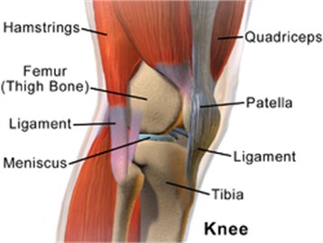
The knee is the largest, complicated mobile hinge joint of human structure as shown in Fig. 1. Three functional components compose the knee joint. They are the patellofemoral articulation, the slidable patellar groove on the front of the femur and the medial and lateral tibiofemoral articulations connecting the femur and the tibia. Knee problem is mostly caused by misalignment, degeneration such as arthritis and trauma. Knee injuries happen very often since it supports static/dynamic human body weight and provides a great range of activities. For instance, a lateral force or torque applied to the knee can cause torn medical collateral ligaments, cruciate ligament injury as well as meniscus injury. The posterolateral corner of the knee has been investigated mostly in the recent years.
Collins et al. [1] conducted a systematic review and meta-analysis to synthesize evidence regarding measurement properties of the Knee injury and Osteoarthritis Outcome Score (KOOS). They concluded that KOOS demonstrates adequate content validity, internal consistency, test-retest reliability, construct validity and responsiveness for age- and condition-relevant subscales.
Parker et al. [2] evaluated knee dislocation and vascular injury from the Department of Trauma and Orthopaedics patient database across a 4 year period from 2010 to 2014. They concluded that the rates of vascular injury are in line with other studies. Also, safety and consistency could be improved with the introduction of a formalized evidence-based protocol for the initial evaluation of knee dislocation and vascular injury.
Hoffmann et al. [3] illustrated the case of a direct knee impact against a reinforced knee brace causing a severe fracture of the tibial plateau. They concluded that even if it may be small, the use of functional knee braces may cause a real risk of injury for adverse players.
Fig. 1Lateral aspect of right knee (Wikipedia)
Guler et al. [4] evaluated the relationship between medial collateral ligament (MCL) injury and degree of internal tibial torsion in patients who had undergone arthroscopic resection due to tears in the posterior one third of the medial meniscus. They concluded that foot femur angle (FFA) and transmalleolar angle (TMA), indicators of internal tibial torsion, may serve as markers for foreseeing clinical improvement and complications following arthroscopic surgery.
Kumar et al. [5] used Solid Edge V19 to model a three dimensional virtual femur bone which is then analyzed for hip contact stresses/forces during normal walking, standing, running and jumping activities. The stress analyses were carried out using ANSYS 14.0 for the femur bone during those activities. The stress results obtained are compared with the previous studies and were found to be optimized.
Shah et al. [6] generated a 3D model of knee joint including bones, ligaments and tendons. The stress, strain, safety factors, safety margins and life of the model are obtained under varying loads by using ANSYS software.
Ishikawa et al. [7] compared the kinematics and contact stresses of mechanically and kinematically aligned total knee arthroplasty (TKA). They suggested that kinematically aligned TKA produces near-normal knee kinematics, but that concerns for long term outcome might arise because of high contact stresses.
Lian et al. [8] developed a bipolar hemi-knee prosthesis with two flexion stages according to a healthy male’s knee morphological profile. It will provide better biotribological performances because it can reduce stresses and potentially wear on the opposing contacting surface during a gait cycle, providing a promising treatment strategy in future joint repair and replacement.
Chen et al. [9] used the finite element method to compare the prosthesis construct behavior subject to the variations of three internal fixations, two loading conditions, two fracture patterns, and four bony strengths. They provided biomechanical information about the differences among retrograde intramedullary nail (RIMN), locking plate (LP), and LP/allograft, and point to which one should be indicated individually for various types of periprosthetic fractures following total knee arthroplasty (TKA).
Beidokhti et al. [10] compare static, dynamic implicit and dynamic explicit solutions in analyses of the knee joint to assess the prediction of dynamic effects, potential convergence problems, the accuracy and stability of the calculations, the difference in computational time, and the influence of mass-scaling in the explicit formulation. They concluded that the computationally less expensive explicit analyses can be used as a diagnostic tool to investigate the effect of various orthopedic interventions in the knee joint.
Huang et al. [11] employed reverse engineering, Noble CFI method and finite element method (FEM) to obtain the outer geometry, to excavate the cancellous bone according to inner canal shape, and to mesh the model of the hollow femur. They concluded that the comparison of natural frequencies, stress, strain, and displacement of both solid and hollow femur are matched to the physical rules.
Ramaniraka et al. [12] developed a numerical model, which is able to evaluate the effect of posterior cruciate ligament (PCL) resection and the different PCL reconstruction techniques on the biomechanics of the knee. They found that a resected PCL induced high compressive forces in the medial tibiofemoral and patellofemoral compartments.
Tanska et al. [13] used multiscale modeling to study how forces are transferred from joint surfaces through tissues to chondrocytes. They found that a medial meniscectomy caused substantially larger (up to 60 %) changes in maximum principal strains in the chondrocyte compared to those in the peri or extracellular matrices.
Walker et al. [14] studied the combined role of the medial meniscus in distributing load and providing stability. The results showed that the posterior horn carried the highest percentage of the shear load when a posterior shear force was applied.
Knee [15] damage or degradation of joint tissue due to improper movement or aging, respectively, will affect the joints activities. Once injured the knee joint is not easy to recover. Therefore, understanding the dynamic characteristics of the knee structure will help to identify the stress distribution of the compartment in moving situation. Although lots of researches have discussed the knee joint problem from medical, clinical, or biomechanical point of view, only a few of them have study them from normal mode, impact, to injury related stress analysis. This study emphasizes the simulation of normal mode, periodic excitation and impact analysis in the knee joint model combined by femur, tibia, fibula, patella, meniscus, and ligaments. The reactions of knee and ankle excited periodically are compared by experimental and simulated results, respectively. The injury is also evaluated through stress analysis.
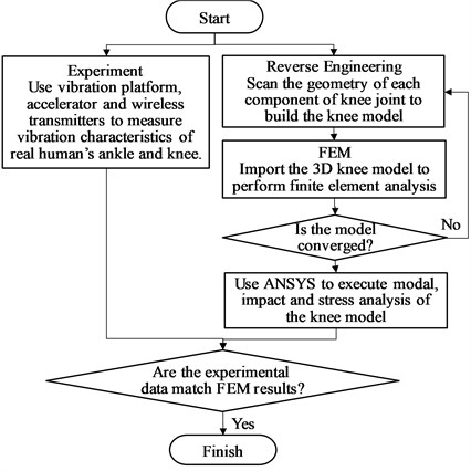
Fig. 2The flow chart of the study
2. Methodology
The flow chart of the study includes two parts shown as in Fig. 2. One is to measure the vibration response of real human ankle and knee on a frequency adjustable vibration platform. The other one used reverse engineering technique to scan the geometry of each component of knee joint to build the knee model. Then, it is imported into ANSYS software. The parameters including meshing, boundary conditions, force constraints are set up and the mesh convergence test is performed. The frequency converged mesh will be used to proceed modal analysis, transient (impact) analysis, etc. The experimental data of periodic excitation are compared with FEM results.
3. Experimental analysis
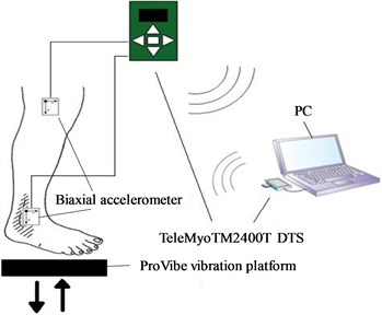
The purpose of measuring vibration responses at knee and ankle from a real person is to compare with the FEM results and verify that the knee model is correct and acceptable. The experimental setup is shown in Fig. 3. One minute measurement is proceeded by a person standing on the vibration platform, Provibe, with two biaxial accelerometers attached on his knee and ankle, respectively. The examinee has 10 minutes rest after each one minute test. The platform is excited with 5 different frequencies from 10 to 50 Hz by incrementing 10 Hz each time. The signals measured by the accelerometers are transferred to PC servo by TeleMyoTM2400T wireless data transmit system (DTS).
Fig. 3The experimental set up
4. Finite element analysis
4.1. Geometric model construction
This study employs reverse engineering equipment 3D optical scanner to capture the geometry of each component of knee joint from a human skeleton model including femur, tibia, fibula, patella, meniscus, and ligaments, respectively. Five major ligaments are built in the model including anterior cruciate ligament (ACL), posterior cruciate ligament (PCL), patellar ligament (PL), lateral collateral ligament (LCL) and medial collateral ligament (MCL).
After smoothing the surface by Geomagic Studio software, the knee joint model is built and imported into ANSYS software, as shown in Fig. 4-5. A higher order 3-D 10-node element, Solid187, and a higher order 3-D 20-node solid element, Solid186, are chosen for bones and ligaments, respectively. Each adjacent surface of the knee joint component is set to be bonded contact to each other. It should be noted that the size, shape, and coarseness of the mesh can affect the analysis accuracy of the knee model. ANSYS Workbench intelligent mesh technology can establish and strengthen the capacity of grid elements. It is effective in ensuring the accuracy of analysis. After meshing the model, the boundary conditions, force constraints, material parameters are set before running the program. The boundary condition of the whole model is set to be clamped at the end of hip joint to simulate the standing position or at the instant of impact with hip joint fixed.
Real human material parameters are used for hard bones and soft tissues [10, 16-18] as shown in Table 1. Normal mode, periodic excitation and impact analysis are performed to understand the acceleration and stress variation for different components of the knee model.
Fig. 4The complete knee joint model
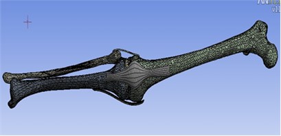
Fig. 5The enlarged knee joint model with detail ligaments
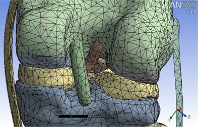
Table 1Real human material parameters
Material | Young’s modulus | Poisson’s Ratio | Density |
Bone | 17,600 MPa | 0.3 | 2132.6 kg/m3 |
Meniscus | 112 MPa | 0.49 | 0.75 kg/m3 |
ACL | 366 MPa | 0.45 | 1.1 kg/m3 |
PCL | 131.5 MPa | 0.45 | 1.1 kg/m3 |
PL | 50 MPa | 0.45 | 1.1 kg/m3 |
LCL/MCL | 400 MPa | 0.45 | 1.1 kg/m3 |
4.2. Finite element convergence analysis
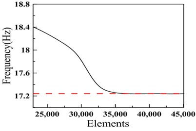
The assembled model of the knee joint includes ten parts: femur, tibia, fibula, patella, meniscus, ACL, PCL, PL, LCL and MCL. It is a very complicated model and lots of contact problems need to be solved before performing the analysis. In FEM, a finer mesh typically results in a more accurate solution but it will increase the computational time. Therefore, one needs to perform a convergence study to get a mesh that balances the accuracy and computing resources. For this complex knee model, the fundamental natural frequency is observed for the convergence study. One can easily find in Fig. 6 that the first natural frequency stops decreasing after the mesh of knee model reaches 35.000 elements. Hence, the meshed knee model with 40.000 elements is chosen for modal, periodic excitation and impact analysis.
Fig. 6Mesh convergence analysis
5. Results and discussions
This study is to investigate the stress characteristics of the dynamic coupled ten pieces of hard bones and soft tissues via modal, periodic excitation and transient (impact) analysis as described in the following sections.
5.1. Modal analysis of knee model
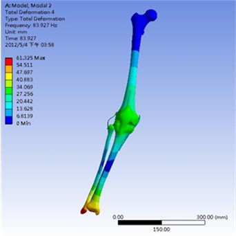
The modal analysis of knee model is performed and the fundamental four natural frequencies (Table 2) and mode shapes are obtained. The first mode (17.2 Hz) is a swing mode in - plane. The second mode (19.1 Hz) is a sliding mode in - plane. The third mode (51.3 Hz) is a bending mode around axis. The fourth mode (83.9 Hz) is a bending mode around axis. These four mode shapes are shown in Fig. 7 to 10, respectively. The red color represents highest amount of deformation in each mode while the blue color represents the lowest one. The natural frequencies of the knee model are lower than that of each single component, namely femur, tibia and fibula. This is because they are connected only by soft tissue ligaments which are flexible but not firmly stable. If the muscles were added into the knee model, the stiffness and frequency would definitely be increased accordingly.
Table 2The first four natural frequencies
Mode | Natural frequency (Hz) |
1 | 17.2 |
2 | 19.1 |
3 | 51.3 |
4 | 83.9 |
Fig. 7Mode 1 (17.2 Hz): swing mode in x-y plane
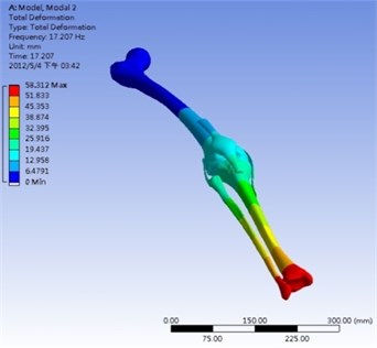
Fig. 8Mode 2 (19.1 Hz): sliding mode in y-z plane
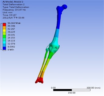
Fig. 9Mode 3 (51.3 Hz): bending mode around z axis
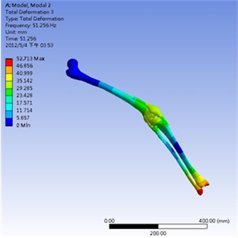
Fig. 10Mode 4 (83.9 Hz): bending mode around x axis
5.2. Comparison of the reactions of knee and ankle via experimental and simulated results
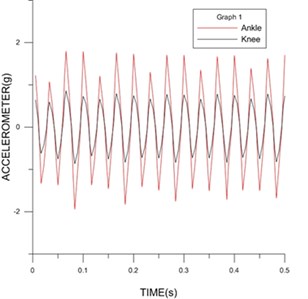
The reactions of knee and ankle excited periodically are compared by experimental and simulated results, respectively. The measured response acceleration of a person’s ankle is around 0.8 g (acceleration of gravity) which is larger than that of the knee, 0.6 g, as shown in Fig. 11. Similarly, the simulated response acceleration of the ankle of the complete knee model is around 1.7 g which is also larger than that of the knee, 0.8 g as shown in Fig. 12. The results are reasonable since the soft tissues, such as meniscus, ligaments, etc., actually absorb the excitation forces and reduce the response. The trend of energy absorption from ankle to knee through measurements and simulations are matched with each other.
Fig. 11Measurement results of the vibration response on ankle and knee excited by ProVibe at 30 Hz periodically
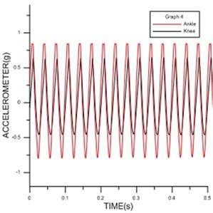
Fig. 12Simulation results of the vibration response on ankle and knee excited by ANSYS at 30 Hz periodically
5.3. Impact analysis of Knee model
Human fully uses his lower limbs to walk, run and fulfill all kinds of sports. Wherein, the knee carries both static weight of human body and the load generated by the acceleration of gravity during movement. Usually, a person’s knee will bear twice of his own weight during walk. In other words, the knee will sustain 1000-1800 N (Newtons) for a person weighted 50 to 90 kg. These forces were used as the excitation of periodic impact to the distal tibia with the duration of 0.1 second each in order to simulate normal gait process. The maximum stress and strain of different component of the knee model with the excitation forces from 1000-1800 N are listed in Table 3. Both stress and strain are increasing with the excitation forces accordingly.
Table 3The maximum stress and strain of different component of the knee model with different excitations
Excitation force (N) | Femur Max. stress (MPa) | Meniscus Max. strain (mm/mm) | Meniscus Max. stress (MPa) |
1000 | 120 | 0.74 | 47.0 |
1200 | 147 | 0.71 | 57.3 |
1400 | 169 | 0.86 | 65.4 |
1600 | 197 | 0.88 | 76.1 |
1800 | 226 | 0.88 | 86.3 |
For hard bone components of the knee joint model, maximum stress 226 MPa occurred at femur head when applying 1.800 N impact force on distal tibia, as shown in Fig. 13. The femur head is most easily fractured when impact occurred and the response maximum stress is larger than its ultimate strength.
Seen from the point of soft tissue, impact loading produces axial forces across the knee, which compresses the meniscus, resulting in circumferential stresses and converted to tensile stresses along the circumferential direction of the meniscus.
If more serious movement or collision happened, the impact force will apparently higher than 1800 N which will increase maximum stress sharply. Once the maximum stress exceeds the ultimate tensile strength of the collagen fibers, the meniscus will be torn and injured [20].
Maximum stress and strain occurred at both medial and lateral meniscus when applying 1.800 N impact force on distal tibia, as shown in Fig. 14-15, respectively.
Fig. 13Maximum stress occurred at femur head when applying 1.800 N impact force on distal tibia
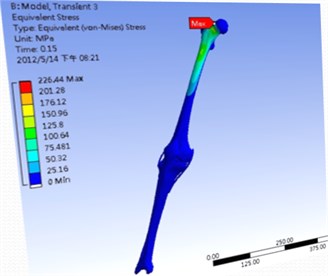
Fig. 14Maximum stress occurred at both medial and lateral meniscus when applying 1.800 N impact force on distal tibia
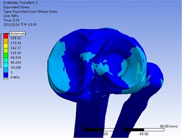
Fig. 15Maximum strain occurred at both medial and lateral meniscus when applying 1.800 N impact force on distal tibia
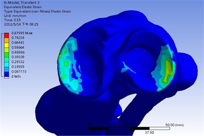
Fig. 16Deformation variations of ankle and knee when applying 1.800 N impact force on distal tibia
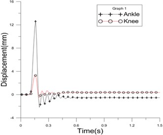
The deformation of knee is smaller than that of the ankle due to energy absorption ability of the menisci, as shown in Fig. 16. Damaged or degraded menisci result in narrowing joint space, decreasing energy absorption, and accelerating cartilage degradation, which are the major hallmarks of osteoarthritis.
6. Conclusions
This paper employs both experimental and FEM analysis to explore the stress characteristics of the dynamic coupled ten pieces of hard bones and soft tissues via modal, periodic excitation and transient (impact) analysis. The result of this research is concluded as follows:
1. 3D complex knee joint model of dynamic coupled ten pieces of hard bones and soft tissues are first built to evaluate the stress variation of the system.
2. The trend of energy absorption from ankle to knee through periodic excitation of both measurements and simulations are matched with each other.
3. Maximum stress occurred at femur head of the hard bone and menisci of the soft tissue. When the stress exceeds the ultimate strength, the component will be damaged and injured. Hence, the injury criterion is to evaluate whether the response stress is higher than the ultimate stress of the component or not.
4. From impact analysis, the deformation of knee is smaller than that of the ankle due to energy absorption ability of the menisci.
References
-
Collins N. J., Prinsen C. A. C., Christensen R., Bartels E. M., Terwee C. B., Roos E. M. Knee injury and osteoarthritis outcome score (KOOS): systematic review and meta-analysis of measurement properties. Osteoarthritis and Cartilage, Vol. 24, 2016, p. 1317-1329.
-
Parker S., Handa A., Deakin M., Sideso E. Knee dislocation and vascular injury: 4 year experience at a UK Major Trauma Centre and vascular hub. International Journal of the Care of the Injured, Vol. 47, 2016, p. 752-756.
-
Hoffmann F., Nuhrenborger C., Hoffmann A., Pape D., Seil R. Unusual injury mechanism of a tibial plateau fracture in relation with a knee brace in handball – a case study. Sports Orthopaedics and Traumatology, Vol. 32, 2016, p. 165-168.
-
Guler O., Isyar M., Karataş D., Ormeci T., Cerci H., Mahirogulları M. Investigating the relationship between internal tibial torsion and medial collateral ligament injury in patients undergoing knee arthroscopy due to tears in the posterior one third of the medial meniscus. The Knee, 2015, https://doi.org/10.1016/j.knee.2015.09.020.
-
Kumar N. K. C., Tandon T., Silori P., Shaikh A. Biomechanical stress analysis of a human femur bone using ANSYS. Materials Today: Proceedings, Vol. 2, 2015, p. 2115-2120.
-
Shah Y., Bhave A., Sonetha V. Fatigue analysis of the knee joint. Procedia Computer Science, Vol. 45, 2015, p. 250-255.
-
Ishikawa M., Kuriyama S., Ito H., Furu M., Nakamura S., Matsuda S. Kinematic alignment produces near-normal knee motion but increases contact stress after total knee arthroplasty: a case study on a single implant design. The Knee, Vol. 22, 2015, p. 206-212.
-
Lian Q., Li D., Jin Z., Wang Z., Sun Y. Patient-specific design and biomechanical evaluation of a novel bipolar femoral hemi-knee prosthesis. Journal of Bionic Engineering, Vol. 11, 2014, p. 259-267.
-
Chen S.-H., Chiang M.-C., Hung C.-H., Lin S.-C., Chang H.-W. Finite element comparison of retrograde intramedullary nailing and locking plate fixation with/without an intramedullary allograft for distal femur fracture following total knee arthroplasty. The Knee, Vol. 21, 2014, p. 224-231.
-
Beidokhti H. N., Janssen D., Khoshgoftar M., Sprengers A., Perdahcioglu E. S., Boogaard T. V. D., Verdonschot N. A comparison between dynamic implicit and explicit finite element simulations of the native knee joint. Medical Engineering and Physics, 2016, https://doi.org/10.1016/j.medengphy.2016.06.001.
-
Huang B. W., Chang C. H., Wang F.-S., Lin A. D., Tsai Y. C., Huang M. Y., Tseng J.-G. Dynamic characteristics of a hollow femur. Life Science Journal, Vol. 9, Issue 1, 2012, p. 723-726.
-
Ramaniraka N. A., Terrier A., Theumann N., Siegrist O. Effects of the posterior cruciate ligament reconstruction on the biomechanics of the knee joint: a finite element analysis. Clinical Biomechanics, Vol. 20, 2005, p. 434-442.
-
Tanska P., Mononen M. E., Korhonen R. K. A multi-scale finite element model for investigation of chondrocyte mechanics in normal and medial meniscectomy human knee joint during walking. Journal of Biomechanics, Vol. 48, 2015, p. 1397-1406.
-
Walker P. S., Arno S., Bell C., Salvadore G., Borukhov I., Oh C. Function of the medial meniscus in force transmission and stability. Journal of Biomechanics, Vol. 48, 2015, p. 1383-1388.
-
Knee. https://en.wikipedia.org/wiki/Knee
-
Kubıcek M., Florian Z. Stress strain analysis of knee joint. Engineering Mechanics, Vol. 16, Issue 5, 2009, p. 315-322.
-
Donahue T. L. H., Hull M. L., Rashid M. M., Jacobs C. R. A finite element model of the human knee joint for the study of tibio-femoral contact. ASME Journal of Biomechanical Engineering, Vol. 124, 2002, p. 273-280.
-
Hadidi P., Paschos N. K., Huang B. J., Aryaei A., Hu J. C., Athanasiou K. A. Tendon and ligament as novel cell sources for engineering the knee meniscus. Osteoarthritis and Cartilage, 2016, https://doi.org/10.1016/j.joca. 2016.07.006.
-
Pauly H. M., Donahue T. L. H. 16 – Bone-meniscus interface. Regenerative Engineering of Musculoskeletal Tissues and Interfaces, 2015, p. 377-407, https://doi.org/10.1016/B978-1-78242-301-0.00016-1.
-
Fischenich K. M., Lewis J., Kindsfater K. A., Bailey T. S., Donahue T. L. H. Effects of degeneration on the compressive and tensile properties of human meniscus. Journal of Biomechanics, Vol. 48, 2015, p. 1407-1411.
About this article

