Abstract
In developing countries like India, unilateral transfemoral amputees encounter with the challenge to select and evaluate the knee joint performance. This study aims to evaluate the response of knee joint on vertical ground reaction forces (vGRFs), walking speed, range of motion (ROM) of joints like hip, knee and ankle joints in first two weeks and enhanced response. Movements of different joints were recorded through VICON motion analysis system. Vertical ground reaction forces were captured through AMTI strain gauzed force plate. It has been observed that in two weeks normalized speed increases 0.41 to 0.49 with 3R20. Range of motion of joints was observed with interesting fact that in general with 3R20, joints angle their respective ROM were more than Jaipur Knee but in same cases in second half of gait cycle Jaipur Knee responded better than 3R20 knee joint.
1. Introduction
Movement is a fundamental aspect of life. Movement is more important than just exercise and does not necessarily require effort with the advancements in technology, use of prosthetics have played an important role in rehabilitation, thereby increasing functionality of various biological systems in the body. During the initial stage, the use of transfemoral amputations brings with itself pain and risk. It can lead to various musculoskeletal complications [1-3] due to unequal distribution of load. Gait symmetry is the most useful method in such cases where transfemoral amputations are used [4]. This aids in the process of summarizing the gait data using which one can adjust the comfort of prosthetics. In the world of prosthetics, the knee joint prosthetic is undergoing extensive research to further improve the functionality of such amputation’s.
In such a process of rehabilitation, the most important process is the amputee’s adaptation to their new prosthetic leg. Based on the manufacturer’s specifications and their own experience, prosthetists prescribe the best possible prosthetics which consists of a foot, ankle and knee. Different prosthetics may suit amputees differently. There is no one single amputation that can work perfectly for everyone. This process of adapting to the new prosthetic not only depends on the overall design and mechanism of the prosthesis [5] but also the psychological state [6] of the amputee. Microprocessor controlled and mechanically passive are the two most common types of prosthesis available today. There are contradictory results on whether a microprocessor-controlled prosthesis helps in improving the amputees’ gait. The use of microprocessor-controlled prosthesis has been promoted in some studies [3, 7, 8]. They proposed that the use of such prosthesis can help to convalescence the gait of the amputee. Segal et al. [9] have shown that the difference in the amputee’s gait using microprocessor controlled and mechanically passive prosthesis is almost nil. According to certain research, the range of motion of the joint and the torques of above the knee [9, 10] and below the knee [11, 12] are different from those of able-bodied subjects and there is huge difference when compared to the control subjects [13]. Winter and Sienko [11] also questioned if amputees could walk symmetrically. They suggested that due to neuromuscular deficiency, the human body may not perform properly under symmetric gait condition. The absence of command over the prosthetic leg increases load on non-prosthetic leg [14]. A new asymmetric condition is established based on the mechanism of the prosthesis and the amputees’ residual system. The increased number of impact forces and the asymmetrical alignment of the body results in an increased stress which can lead to low back pain and osteoarthritis. One of the main reasons behind the injury suffered by runners [15] is soft tissue loading which can be defined using the loading rate. The slope of the first peak of the ground reaction forces is used to calculate the loading rate or the transient impact.
Based upon the literature review, although Mishra et al. [16] have evaluated Jaipur Knee’s gait performance, its comparative performance with other joints hasn’t been done. The data on the gait performance of the Indian Trans femoral amputees using the Jaipur Knee joint is very acute. The Jaipur Knee joint mimics the movement of a normal knee using a polycentric joint. It has a four-bar chain geometry and combines an upper and lower body blocks with a central and two side links using four steel bolts. Sections for socket and pylon attachment are available. It is fabricated using an oil-infused Nylon-6 polymer. Bhagwan Mahavir Viklang Sahayta Samiti (BMVSS) Jaipur provide free of cost Jaipur Knee joint to thousands of Indian amputees [17]. Hence, in order to aid the clinicians as well as the amputees, it was important to study various performance parameters during gait. The aim of the paper is to analyse the spatiotemporal framework during gait performance. Thorough assessment of the relative effect of time-based changes of spatiotemporal parameters is the main focus of the paper. This is done using gait performance after the prosthetic adjunction with the Jaipur Knee joint in Indian amputees.
The loading rate is assumed to be a function of vertical heel velocity. Irrespective of the knee design, the amputee’s adaptation and motor skill’s advancement has been evaluated. Therefore, the amputee’s adaptation and control over the prosthetic knee can be indicated by finding a negative relation between the transient loading rate of either leg and the vertical heel velocity in an active amputee in the short term (Table 1).
Table 1Grouping of the Prosthetic knee and foot used in this study
Item | Type of prosthetic knee | Type of prosthetic foot and ankle | Component weight (kg) |
1 | 3R20 | Jaipur foot | 0.890/0.585 |
2 | 3R80 | Jaipur foot | 1.240/0.585 |
3 | Jaipur knee | Jaipur foot | 1.240/0.585 |
2. Methods
2.1. Participants
Sixteen volunteers (recognized as AKA) participated in the study. They suffered with no other chronic diseases (shown in Table 1). Before starting with the experiment, a written consent was taken from all the participants. Each subject had been using the Jaipur knees for a couple of users. As per the recommendations of trained clinical professionals, participants were asked to use the 3R80 knee for a stipulated time period to get accustomed to the prosthesis. For precise results, the patients went through a thorough assessment of their physical health to make sure they didn’t have any injury that might upset the results.
2.2. Study design
In this study, the parameters were recorded by conducting the gait experiments repeatedly. Markers were placed at prominent bony positions following Heinski’sf guidelines (Fig. 1). Considering the knee joint as a single variable, the gait lab technicians only replaced the knee joints. To prevent any discrepancy, different prosthetic parts like the suspension system, socket system and foot system were not changed. The artificial leg and other mass related properties were also kept identical. If the prosthesis is not properly aligned, it can tissue injuries in the future due to the irregular pressure distribution and lack of comfort [18]. The subjects underwent a thorough checkup by the Gait lab professionals to ensure a perfect fit, thereby reducing the chances of any aberrance.
Two sessions were conducted to collect the experimental data. Initially the Jaipur Knee was used to record the readings. Each subject was asked to walk on an 8 m pathway at a comfortable pace. The participants recorded an average speed of 1.15 m/s (SD = 0.25 m/s). At the end of the first session, the 3R80 joint replaced the Jaipur Knee joint in transfemoral prosthesis. To get used to it, the subjects were asked to wear prosthetics with 3R80 joint till they could walk with it easefully. As per the subjects’ feedback and clinician’s assessment, the average acclimation time estimated was 14 weeks (SD = 6 weeks). Once the subjects acclimated to the new prosthetics, the second set of data was recorded. This time too, the subjects walked at a pace comfortable to them just like the first session. This time, an average speed of 1.19 m/s (SD = 0.23 m/s) was recorded. Consequently, the essential requirements were completed for both the knee joints.
Fig. 1Schematic representation for positioning of marker used in this study
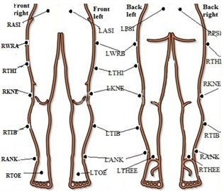
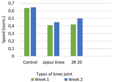
Fig. 2Speed with different prosthetic knee vs control subject
3. Results
The data was divided into two parts: one collected when the new prosthetic knee was fitted and the other one taken two weeks later. The leg length which was measured using the coordinates of the foot heel and the hip joint was used to normalize the gait speed (Fig. 2).
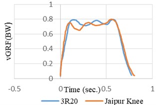
Fig. 3Normalized average vGRF versus time graph for different knee joints in prosthetic leg during comfortable self-selected speed
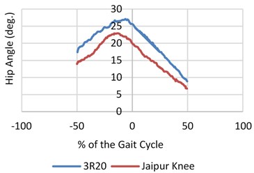
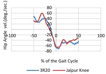
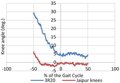
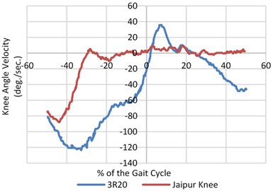
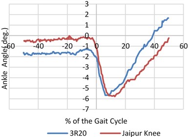
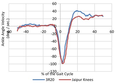
The signals were balanced and synchronized when the heel contact occurred or at the zero percent of the gait cycle as the entire survey was focused before and during the heel contact. This was done to have a proper analogy between the signals. The angular velocity and range of motion of the joint angles was measured during walking at different pace during normal walking as shown in Fig. 4. An inspection of the data (hip, knee and joint angles) showed that both the legs had the same flexion or extension pattern. There was almost no extension after the heel contact and very little flexion during the swing on the prosthetic side of the knee joint (20/5 deg. Versus 60/20 deg.).
Contrary to the CS ankles, there was no activity by the ankles from 50 % to 15 % of the gait cycle on the prosthetic side. Momentarily prior to the heel contact, the CS hip’s range of motion continued to increase to –20-degree angle and trail hip (ROM) heightened about 40 % from 30 to nearly 39 degree. Fig. 3 represents the mean vGRF versus time while the CS and the amputees walked at a self-chosen speed. Both the intact and prosthetic leg showed a larger first peak than the CS.
Fig. 4Mean value of angular speed and motion range for three joints (hip, knee and ankle) for both prosthetic leg and normal leg with different knee joints
4. Discussion
With the availability of so many commercial prosthetic knees, it is difficult to conclude how they might affect the functionality of the amputee. Our aim was to study the adaptation of a unilateral above knee amputee by finding a evaluating a relationship between the transient impact and the vertical heel velocity. After a short period of time, the biomechanical adaptation was visible despite the imbalance between contralateral and ipsilateral legs. An increase in plantar flexion angle leads to an increase in the walking speed. Preparing the leg for less plantar flexion, similar mobility can be achieved by creating a torque about the hip joint [19], which can be understood as an amputee’s strategy. A greater range of motion was shown by the amputee’s leg on the prosthetic side when compared to the CS. This may lead to a greater metabolic energy expenditure. Before the heel contact the vertical heel, velocity is not zero for neither the amputee who bears the prosthetic knee nor the CS [19]. This is in contradiction to the results suggested by Winter.
5. Conclusions
The prosthetic side of the amputee’s hip underwent an initial extension and the extension continued even after the heel contact occurred for about 10 % of the gait cycle (Fig. 3). A thorough study of the angular rotation of the amputee’s hip indicated that the extension continued to happen (before the heel contact) for nearly 14 % of the gait cycle. In the case of CS, the hip was briefly stationary (Fig. 3). This is contrary to the amputee’s case. This study also advocates why the amputees tend to rely more on their unscathed leg. To generalize the outcome for our study, there must be an increase in the number of participants. We observe and implement a way to how the gait of an active amputee will adapt to the prosthetic knees without being confused and mixed up with other parameters that may be different for different amputees due to factors such as dimension of amputation, approach as well as the level of confidence during walking, etc. The parameters and functions calculated by the motion capture system were studied. This can be related by expressing it as the experiment’s layout on the prosthetic knee arrangement.
In above knee amputation, challenge that comes in our Way is prosthetic alignment that needs to be implemented by an expert prosthetist. To be more consistent and avoid any misalignments, all assessments were done in the same hospital by single specialist. Another limitation that we face is in placing the passive markers on the anatomical landmarks. Hence this job was also done by a single specialist. To understand the kinematics of the knee joint, motion capture systems are used which are based on biomechanical models which consider the joints to be suitable mechanical points like the cylindrical or the revolute joints rather than performing both translational and rotational simultaneously resulting in inaccurate kinematics. But we considered the biomechanical models to be the same for all the models to avoid inconsistency. Parameters like centre and axis of rotation of the joints, height and width of the limb along the medial plane were described using static markers regardless of the mechanical character of prosthetic legs or muscle masses on the result.
References
-
Bautmans T., Jansen I., Van Keymolen B., Mets B. Reliability and clinical correlates of 3D-accelerometry based gait analysis outcomes according to age and fall-risk. Gait Posture, Vol. 33, Issue 3, 2011, p. 366-372.
-
Kulkarni A., Adams J., Thomas J., Silman E. Association between amputation, arthritis and osteopenia in British male war veterans with major lower limb amputations. Clinical Rehabilitation, Vol. 12, 1998, p. 348-353.
-
Johansson J. L., Sherrill Dm, Riley Po, Bonato P., Herr H. A clinical comparison of variable-damping and mechanically passive prosthetic knee devices. American Journal of Physical Medicine and Rehabilitation, Vol. 84, 2005, p. 563-575.
-
Jaegers H. J., Arendzen S. M. H. J., De Jongh J. H. The prosthetic gait of unilateral transfemoral amputees: a kinematical study. Archives of Physical Medicine and Rehabilitation, Vol. 76, Issue 8, 1995, p. 736-743.
-
Seroussi R. E., Gitter A., Czerniecki J. M., Weaver K. Mechanical work adaptations of above-knee amputee ambulation. Archives of Physical Medicine and Rehabilitation, Vol. 77, Issue 11, 1996, p. 1209-1214.
-
Horgan O, Maclachlan M. Psychosocial adjustment to lower-limb amputation: a review. Disability and Rehabilitation, Vol. 26, 2004, p. 837-850.
-
Lui Z. W., Awad M. I., Abouhossein A., Dehghani Sanij A.-A., Messenger N. Virtual prototyping of a semi-active transfemoral prosthetic leg. Proceedings of the Institution of Mechanical Engineers, Part H: Journal of Engineering in Medicine, Vol. 229, 2015, p. 350-361.
-
Kaufman K. R., Levine J. A., Brey R. H., Iverson B. K., Mccrady S. K., Padgett D. J. Gait and balance of transfemoral amputees using passive mechanical and microprocessor controlled prosthetic knees. Gait and Posture, Vol. 26, 2007, p. 489-493.
-
Segal A. D., Orendurff M. S., Klute G. K., Mcdowell M. L., Pecoraro J. A., Shofer J., Czerniecki J. M. Kinematic and kinetic comparisons of transfemoral amputee gait using C-Leg and Mauch SNS prosthetic knees. Journal of Rehabilitation Research and Development, Vol. 43, 2006, p. 857-870.
-
Farahmand F., Rezaeian T., Narimani R., Parisa Hejazi Dinan Kinematic and dynamic analysis of the gait cycle of above-knee amputees. Scientia Iranica, Vol. 13, 2006, p. 261-271.
-
Winter D. A., Sienko S. E. Biomechanics of below-knee amputee gait. Journal of Biomechanics, Vol. 21, 1988, p. 361-367.
-
Bateni H., Olney S. Kinematic and kinetic variations of below-knee amputee gait. Journal of Prosthetics and Orthotics, Vol. 14, 2002, p. 2-10.
-
Schaarschmidt M., Lipfert S. W., Meier Gratz C., Scholle H.-C., Seyfarth A. Functional gait asymmetry of unilateral transfemoral amputees. Human Movement Science, Vol. 31, 2012, p. 907-917.
-
Röhrle H., Scholten R., Sigolotto C., Sollbach W., Kellner H. Joint forces in the human pelvis-leg skeleton during walking. Journal of Biomechanics, Vol. 17, 1984, p. 409-424.
-
Hreljac A. Impact and overuse injuries in runners. Medicine and Science in Sports and Exercise, Vol. 36, 2004, p. 845-849.
-
Mishra P., Singh S., Ranjan V., Singh S., Vidyarthi A. Performance evaluation of Jaipur Knee joint through kinematic and kinetic gait symmetry with unilateral transfemoral Indian amputees. Journal of Medical Systems, Vol. 43, Issue 3, 2019, p. 1-8.
-
Jaipur Knee, https://www.jaipurfoot.org/what_we_do/prosthesis/stanford_jaipur_knee.html.
-
Radin E. L., Parker H. G., Pugh J. W., Steinberg R. S., Paul I. L., Rose R. M. Response of joints to impact loading – III: relationship between trabecular microfractures and cartilage degeneration. Journal of Biomechanics, Vol. 6, Issue 1, 1973, p. 51-54.
-
Winter D. A. Foot trajectory in human gait: a precise and multifactorial motor control task. Physical Therapy, Vol. 72, 1992, p. 45-53.
About this article

