Abstract
This short paper describes a problematic of a small hydroelectric power station machinery vibration diagnostics. The vibration diagnostics of a power station machinery is very specific, machinery contains many possible damaged rotating parts including a turbine rotor. Non-stationary strength pulsing caused by water flow can be generated. The paper describes problems with the correct determination of a small hydroelectric power station machinery failure.
1. Introduction
The modern trends of energy production are renewable sources especially oriented. One of the most important and used electric energy generating technology solutions are a hydroelectric power stations. The energy produced by hydroelectric power stations sis relatively clean without a excessive pollution.
The machinery of a hydroelectric power station is necessary to keep in good condition. The continuous maintenance for trouble-free operation is necessary. The vibrodiagnostics for the failure identification is very useful solution.
The vibrodiagnostics of a hydroelectric power station machinery is specific by the other possible vibrations caused by the water flow. The non-constant strength, torque and RPM by the water flow can be generated.
2. Hydroelectric power station machinery diagnostics
The power station is more than one hundred years old and a significant part of machinery is original. The power station is powered by three Francis turbines in a horizontal modification. The maximal water flow during the turbines about 5500 l/s can be. The maximal turbines power is about 150 kW. The turbine output shaft speed is about 170 RPM. The single stage gearbox for the shaft speed changing is used.
2.1. Single stage gearbox
The single stage gearbox for the shaft speed increasing is used. The gearbox was an original old part made more than eighty years ago. The herringbone gears in the gearbox were used. The input shaft speed is 170 RPM and output shaft speed is 750 RPM, the transmission ratio is 4,41. The friction bearing for the housing of input shaft are used. The output shaft to the roller bearing is mounted.
2.2. Measurement places
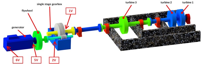
To choose measurement places for the successful vibration analysis was necessary. The many places of machinery are hidden and no possible to apply accelerometers there. The housing of the machinery shafts was chosen as a perfect places for the main vibration measurements. The final most important places of measurement are on Fig. 1. The measurement places as a 1 V, 2 V, 5 V, 6 V are labeled.
The chosen places for vibration measurement are 1 V – the friction bearing of single stage gearbox input shaft, 2V- the roller bearing of the gearbox output shaft, 5 V, 6 V – the generator rotor bearings.
Fig. 1The hydroelectric power station scheme – places of measurement
2.3. Measurement and results
The SKF Microlog CMVA 10 analyzer for the vibration diagnostic was used. The Microlog analyzer is single channel professional equipment for the FFT vibration analyzing. The SKF Microlog analyzer is possible to use in many different applications during the technical vibration analyses. The accelerometer CMSS 793L for the measurement was switched.
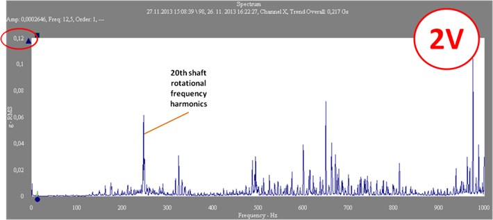
Fig. 2The vibration specter – 1 V, 2 V, before repair
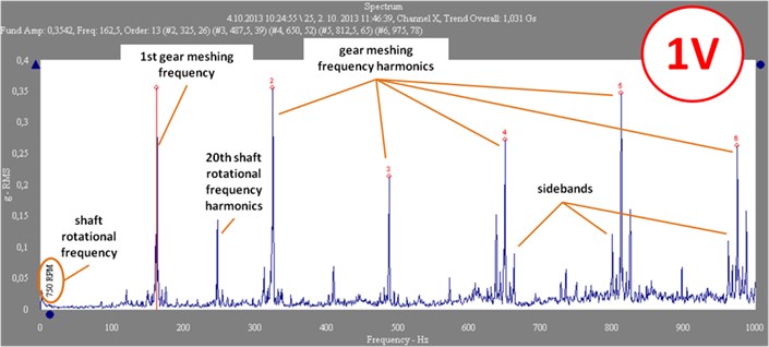
The gearbox damage was evident and the repair was necessary. The one of the main friction bearing of input shaft was damage. The damage was define by the generated harmonic and interharmonics rotor frequencies. The gear frequency modulation was diagnostic, the gear could be damaged too. The main vibration specter abnormalities are shown on the Fig. 2 where the vibration specters measured near of gearbox shaft housing (places 1 V, 2 V) are depict.
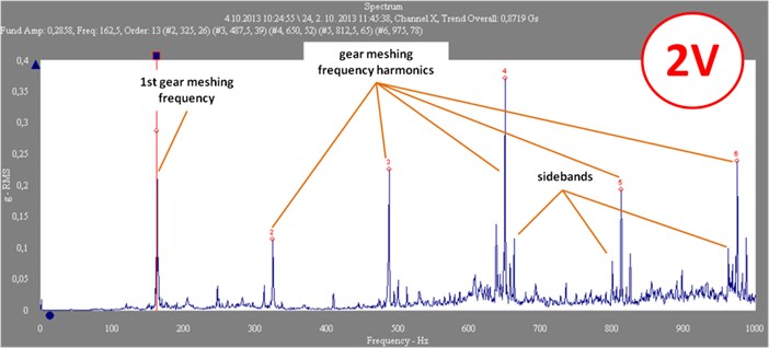
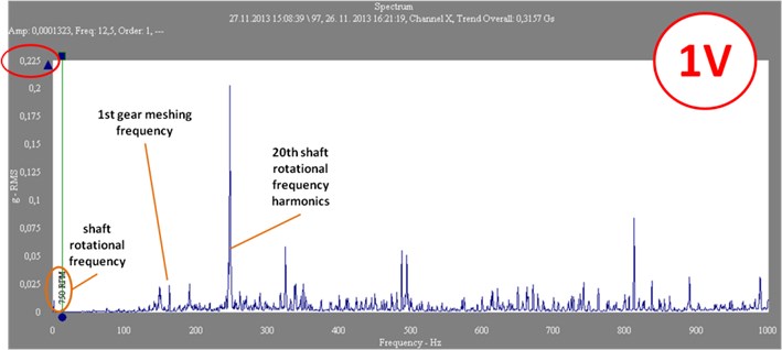
The second comparing vibration measurement after the bearing repair was performed. The vibration specters are on Fig. 3.
Fig. 3The vibration specter – 1 V, 2 V – after repair
The maximal measured acceleration values are in Table 1. Table 1 compares the values before and after the repair. The maximal acceleration value after repair are more than 60 % lower than before. The gearbox was labeled as a “class A” (according standard ČSN ISO 10 816-1) after the repair- perfect condition and a long service life.
Table 1Maximal measured acceleration
Measurement place | Before repair | After repair |
Vibration severity of acceleration [mm·s-2] | ||
1 V | 1,03 | 0,31 |
2 V | 0,87 | 0,21 |
5 V | 0,085 | 0,088 |
6 V | 0,082 | 0,084 |
3. Conclusions
This short paper talks about a vibration diagnostics of a small hydroelectric power station machinery. The parameters of the power station are in the beginning. The main goal of the paper is a measuring and evaluation of the power station machinery diagnostic parameters. The measurements were performed in the specified places of machinery- bearings of single stage gearbox and generator. The measured acceleration is on the included graphs. It is apparent that the gearbox input bearing was damaged. The repair was recommended. The measurements were performed after the repair once more. More than 60 % reduction of vibration happened. The worries about an influence of the water flow vibration effect was unnecessary.
References
-
Tomeh E. Diagnostic Methodology of Rolling Element and Journal Bearings. Technical University of Liberec, Liberec, 2007.
-
Tomeh E. Technical Diagnostics: Vibration Diagnostics of Machines and Equipment. Technical University of Liberec, Liberec, 2015.
-
CSN ISO 10816 Vibration analysis of Machines and Equipments.
About this article

The results of this Project LO1201 were obtained with co-funding from the Ministry of Education, Youth and Sports as part of targeted support from the “Národní Program Udržitelnosti I” Program.
