Abstract
To study the problem of vibration of harmonic response of robotic arm under the load, a three-dimensional model of the frame of the robotic arm was created in the Solidworks, then the model was imported into ANSYS for modal analysis. We obtained the frequency of natural vibration and the effect of response of the key components of robotic arm by above analysis. The natural frequency of the robotic arm can be kept away from the frequency of vibration of machine completely, and thus poor working conditions caused by resonance can be avoided. Next the analysis of harmonic response was also performed on the basis of modal analysis. According to the above analysis we obtained displacement diagram and stress distribution diagram of harmonic response. The analysis has a referenced value to design and improve the structure of robotic arm.
1. Introduction
Mechanical arm is a multi-joint manipulator facing to industrial fields, an automatic machine device, and a machine that can realize various functions by its own power and system of control [1-5]. But along with our further research on robotic arm, the vibration and noise of robotic arm have attracted people’s attention. All kinds of industrial robotic arms are almost in the environment of vibration, which may cause resonance, fatigue and even the damage of robotic arm’s structure, therefore, if we comprehend the characteristics of stiffness of robotic arm, we will avoid losses caused by resonance in its using [6-9].
Modal Analysis is an important analysis method for analysis of the characteristic of vibration. We can determine the characteristics of vibration of robotic arm and obtain parameter of modal by this way. It is an important basis on designing structure under the dynamic load [10-13]. In the paper we created a three-dimensional model for frame of robotic arm in the SOLIDWORKS, made a modal analysis in the ANSYS, and obtained the natural frequency of vibration and the effect of response of the natural frequency. Next, we performed the analysis of simulation of harmonic response on the basis of modal analysis, and then obtained the stress and the displacement of robotic arm in the case of vibration of agriculture intelligent machine.
It provides a theoretical basis for the optimization of structure of the robotic arm.
2. The working parameters of the robotic arm
In the paper, the main part of the robotic arm is composed by arm, wrist and the end effector. The arm is an important component to support objects caught, wrist and end effector. In order to achieve the movement of the arm, industrial manipulator arm is usually composed by a part of driven arm motion and source. The role of the end effector is grabbing objects and carrying them to the specifying location at predetermined requirements when it works. The wrist is the part of connecting arm and end effector. The technical parameters of robotic arm are shown in the Table 1. The material of robotic arm uses 45#steel, the rest uses structural steel, the parameter of 45#steel is shown in the Table 2.
Table 1The parameters of robotic arm
Name | Length / mm | The angle of rotating / (°) | Quality / kg |
Arm | 5500 | –90-90 | 21.74 |
Wrist | 4500 | –56-56 | 17.58 |
End effector | 3000 | –90-90 | 4.15 |
Table 2The parameters of 45 steel
Number of shear elastic model | Poisson’s ratio | Yield limit |
208 | 0.3 | 355 |
3. Establishment of model of finite element analytical
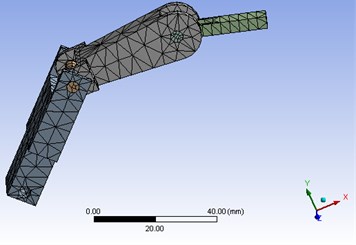
A 3D model of robotic arm was established in SOLDWORKS, after we comprehensively considered the structural feature and amount of solution, and simplified the structure of the robotic arm on the premise of keeping the main structure. The established model is shown in the Fig. 1. The 3D model was led in ANSYS software via SOLIDWORKS and ANSYS interfaces. Inertial frame of boom system was set as follows: we applied the constraint of distal displacement for boom system to make axial direction free. The model regular part is divided into swept grids, while the irregular part is divided into free grids, according to the statistic, the model has 29321 units and 9640 nodes after dividing grids. As shown in the Fig. 2.
Fig. 1Three-dimensional model of key components of robotic arm
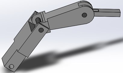
Fig. 2Robotic arm after dividing the gridding
4. Modal analysis of robotic arm
To avoid the damage of resonance to mechanical structure before it works in reality, the modal analysis is necessary to judge whether there is a resonance. Based on the results of modal analysis, the stability of device can be guaranteed through avoiding these frequencies or reducing the effect of excitation of these frequencies before the practical work of robotic arm [14, 15]. Modal analysis of key components of robotic arm is established by ANSYS. Through modal analysis, we can obtain natural frequencies, modal shapes, parameters of modal damping. According to the results of analysis of vibration, we carried out the analysis of vibration and concluded that the stability of robotic arm can be guaranteed through avoiding these frequencies or reducing the effector excitation of these frequencies in the largest degree.
The results of modal analysis of robotic arm are shown in the Figs. 3-8. We can see that the first-order mode of vibration was that the robotic arm rotated along axis, and the effect of response was that the wrist was distorted in radial direction, and the end effector was bent; The second-order mode of vibration was that the robotic arm swung along , and the responding effect was that end effector was distorted, the connecting shaft of arm and wrist was distorted in radial direction, and the connecting shaft of wrist and end effector was distorted in axial direction; The third-order mode of vibration was that robotic arm swung along , and the responding effect was like to the second-order mode of vibration; The fourth-order vibration mode was that the mechanical swung along radial direction while rotating along , , axial directions, and the responding effect was that the wrist was distorted, and the end effector had a complex displacement; The fifth-order mode of vibration was that the rotary cutter shaft swung along radial direction while rotating along , , axial directions, and the responding effect was that the connecting shaft of arm and wrist was distorted in radial and axial direction, and the end effector was distorted and had a complex displacement; The sixth-order vibration mode was that the mechanical arm swings along radial direction while rotating along , , axial directions, and the responding effect was that the connecting shaft of wrist and the end effector was distorted in radial and axial direction, the connecting shaft of arm and wrist was distorted in radial and axial direction, and the end effector was distorted and had a complex displacement.
Fig. 3The first order displacement diagram of modal
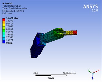
Fig. 4Second order displacement diagram of modal
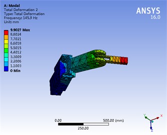
Fig. 5Third order displacement diagram of modal
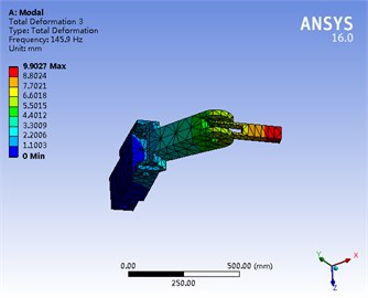
Fig. 6Fourth order displacement diagram of modal
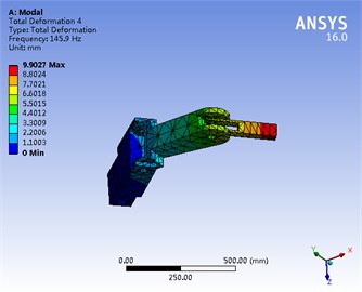
Fig. 7Fifth order displacement diagram of modal
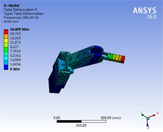
Fig. 8Sixth order displacement diagram of modal
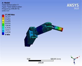
When the frequency of vibration is closed to the natural frequency of vibration in its practical works, the phenomenon of resonance will occur. We obtained that the natural frequency of the robotic arm is 68 Hz. When the frequency of vibration is closed to 68 Hz, there will be the phenomenon of resonance. When the robotic arm is working, its parts will be damaged or affected by the resonance.
5. Analysis of harmonic response
Analysis of harmonic response is a kind of technology used to determine the steady response of the structure under the load according to the sine law of change over time. The function of excitation is a sine function with constant amplitude. The distribution function of the load is:
where is function of excitation, is amplitude of exciting force, is frequency of excitation, is the angle of direction of total force and axis, 0-180°.
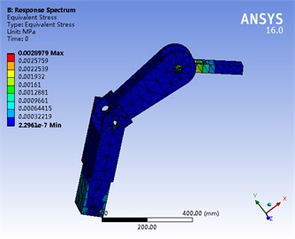
According to the results of modal analysis, we can know that the key components of robotic arm will not be subjected by the resonance when it works. To analyze the specific responding effects of robotic arm, the analysis of harmonic response also need to be conducted on the basis of modal. Curves of displacements and stress of responding frequency of each section of arm in three axes direction under the action of vibration force are shown in the Fig. 9-12.
Analysis of harmonic response of the finite element model was conducted on the basis of modal analysis. The analysis of harmonic response was based on ANSYS. The frequency of vibration varies within 65-72 Hz, therefore, the frequency band of analysis of harmonic response will be within 65-72 Hz. Vibration was produced by amplitude spectrum 0.01 m. Run “solve”, and then the displacement and stress responses of robotic arm can be obtained. As shown in the Figs. 9-12. The maximum displacements of robotic arm in , and were 1.7465e-5, 2.0197e-5, 1.373e-7, the maximum stresses of robotic arm was 0.003 MPa. Under the influence of machine’s vibration, the displacements and stresses of robotic arm were very little, which will not impact the strength and stability of robotic arm.
Fig. 9Displacement nephogram of harmonic response in X
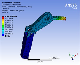
Fig. 10Displacement nephogram of harmonic response in Y
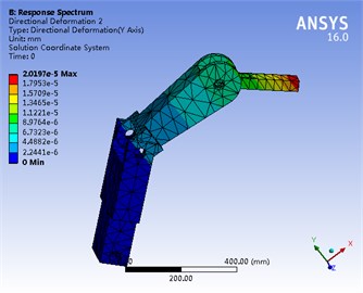
Analysis of harmonic response of the finite element model was conducted on the basis of modal analysis. The analysis of harmonic response was based on ANSYS. The frequency of vibration varies within 65-72 Hz, therefore, the frequency band of analysis of harmonic response will be within 65-72 Hz. Vibration was produced by amplitude spectrum 0.01 m. Run “solve”, and then the displacement and stress responses of robotic arm can be obtained. As shown in the Fig. 9-12. The maximum displacements of robotic arm in , and were 1.7465e-5, 2.0197e-5, 1.373e-7, the maximum stresses of robotic arm were 0.003 MPa. Under the influence of machine’s vibration, the displacements and stresses of robotic arm were very little, which will not impact the strength and stability of robotic arm.
Fig. 11Displacement nephogram of harmonic response in Z
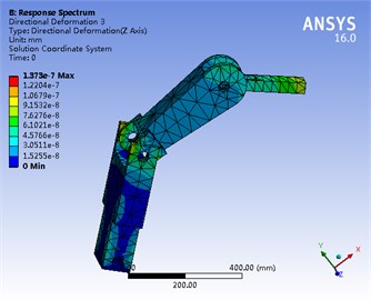
Fig. 12Stress nephogram of harmonic response of robotic arm
6. Conclusions
1) To better understand the rules of the dynamic response of the system of robotic arm, modal analysis of robotic arm was established by ANSYS. We implemented analysis of harmonic response based on virtual prototype. Based on these results, we carried out the analysis of vibration and concluded that the damage of resonance to structure can be avoided through keeping away from these frequencies or reducing the effect of excitation of these frequencies in the largest degree.
2) The results of the modal analysis show that: the transformative area caused by the resonance mainly distributes in the hinge shaft and hole on the surface, which includes bending vibration and torsional vibration etc. To make it better meet practical application, modified measures also should be taken to adjust the local stiffness (such as increase the thickness of boom).
3) Analysis of harmonic response of the model finite element was conducted on the basis of modal analysis. Under the condition of vibration we obtained displacements and stress of robotic arm, which provides a theoretical basis for the design and optimization of robotic arm.
References
-
Wu P., Wu C. Motion planning and coupling analysis based on 3-RRR(4R) parallel mechanism. International Journal of Mechanics and Materials in Design, Vol. 4, Issue 3, 2008, p. 325-331.
-
Wu P., Xiong H., Kong J. Dynamic analysis of 6-SPS parallel mechanism. International Journal of Mechanics and Materials in Design, Vol. 8, Issue 2, 2012, p. 121-128.
-
Sachindra M. Shape optimization of revolute-jointed single link flexible manipulator for vibration suppression. Mechanism and Machine Theory, Vol. 75, Issue 1, 2014, p. 150-160.
-
Ryan J. C., David E. Z., Leila J. B., et al. Saturated proportional derivative control of flexible-joint manipulators. Robotics and Computer-Integrated Manufacturing, Vol. 30, Issue 6, 2014, p. 658-666.
-
Steve U., Jurek Z. Modeling and direct adaptive control of a flexible-joint manipulator. Journal of Guidance, Control, and Dynamics, Vol. 35, Issue 1, 2012, p. 24-39.
-
Wang Xuekui Research on Dynamical Modeling and Control of Flexible Manipulator. Northeastern University, Shenyang, 2011.
-
Korayem M. H., Irani M., Rafee Nekoo S. Load maximization of flexible joint mechanical manipulator using nonlinear optimal controller. Acta Astronautica, Vol. 69, Issue 1, 2011, p. 458-469.
-
Cai Guoping, Hong Jiazhen Assumed mode method of a rotating flexible beam. Acta Mechanica Sinica, Vol. 37, Issue 1, 2005, p. 48-56.
-
Subudhi B., Morris A. S. Dynamic modelling, simulation and control of a manipulator with flexible links and joints. Robotics and Autonomous Systems, Vol. 41, Issue 1, 2002, p. 257-270.
-
Fan Jihua, Zhang Dingguo B-spline interpolation method for the dynamics of rotating cantilever beam. Journal of Mechanical Engineering, Vol. 48, Issue 23, 2012, p. 59-64.
-
Wu P., Wu C. Motion planning and coupling analysis based on 3-RRR(4R) parallel mechanism. International Journal of Mechanics and Materials in Design, Vol. 4, Issue 3, 2008, p. 325-331.
-
Wang L., Li Huiqin, Li Yan, Zhang Shanshan Finite element analysis of the frame of the self-propelled combine harvester. Jiangsu Agricultural Sciences, Vol. 40, 2012.
-
Zhang T. Fatigue analysis of electric vehicle frame based on ANSYS workbench. Journal of Shandong Jianzhu University, Vol. 28, 2013.
-
Wu P., Xiong H., Kong J. Dynamic analysis of 6-SPS parallel mechanism. International Journal of Mechanics and Materials in Design, Vol. 8, Issue 2, 2012, p. 121-128.
-
Shabana A. A. Flexible multi body dynamics: review of past and recent developments. Journal of Multibody System Dynamics, Vol. 1, Issue 2, 1997, p. 189-222.
